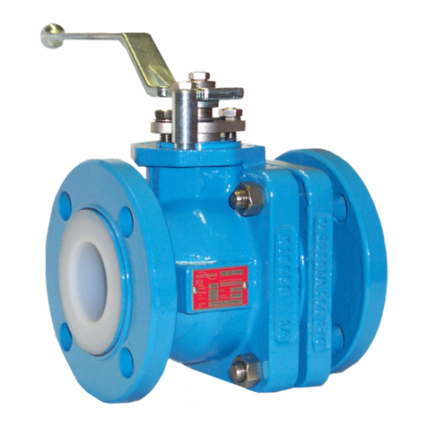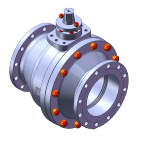
AKH7 - atomac ball valve for glass system
Ahaus GmbH
von-Braun-Straße 19a
D-48683 Ahaus
Postfach 1162 D-48661 Ahaus
Telefon: +49(0) 2561-686-100
Fax: +49(0) 2561-686-200
Register: 7
Page: 4
Date: 04.1995
Revision: 06.2020
Technical Manual
Disassembly Instructions AKH7/GK
Assembly Instructions AKH7/GK
025
027
028
050
040
010
028
027
025
150
120
100
065
060
170
110
304
300
310
For all jobs which are to be carried out on an installed valve, the works safety requirements and
the general accident prevention instructions must be observed. Moreover, the general installation
and maintenance instructions for atomac uorcarbon resin lined valves must be considered.
1. Prior to disassembly, the valve must be cleaned of all uid according to the abovementioned
instructions. Particular care must be taken that during the rinsing and draining of the piping
the valve is opened and closed repeatedly. These cycles (opening and closing) are to be
repeated when emptying the piping. Only when following this procedure, is it ensured that all
remaining pressure inside the body (stem guide and ball seats) is eleminated.
2. Put valve on a work bench with a soft cover (rubber mat). To remove the ball (050), put
hand lever (300) in closed position (90° to longitudinal axis of the
valve). The ball can
easily be pushed out of the body.
3. Remove hand lever (300) with the hexagon bolt (304).
4. Loose hexagon nuts (110), remove gland follower (060) and
gland insert (065). If necessary, stud bolts (120) can also be
removed now.
5. Remove stem (040) by pushing it down through the body. Care
must be taken not to damage the body liner.
6. Chevron packing (100) can easily be removed.
The general installation and maintenance instructions must be observed.
1. Screw stud bolts (120) into body (010).
2. Insert stem (040) from inside of body in such a way that the at side is parallel to the longitu-
dinal axis of the body (010).
3. Insert chevron packing (100).
4. Install gland insert (065), gland follower (060), safety washer (150), hexagon nuts (110) and
grounding device (170) also on valves top.
5. Assemble hand lever (300) onto stem (040) with the hexagon bolt (304).
6. Insert ball (050) to valve stem by pushing the ball in a downward motion through valve body.
7. Turn handlever (300) 90° o longitudinal of body (open position).
8. Insert side piece (025) on both sides into body (010).
9. Install split ring (027) with cylinder head bolts (028) on the side piece (025).
10. Assemble stops (310) with hexagon bolt (312)
Your distribution partner:
Blindeisenweg 31 • D-41468 Neuss • Tel.: +49 2131 / 15 39 28-0 • Fax: +49 2131 / 15 39 28-99 • info@fergo.eu • www.fergo.eu
