manuals.online logo
Brands
  1. Home
  2. •
  3. Brands
  4. •
  5. Flowserve
  6. •
  7. Control Unit
  8. •
  9. Flowserve Valtek Mark Six User manual

Flowserve Valtek Mark Six User manual

6-1
Rev. 1/88 Valtek No. 49016
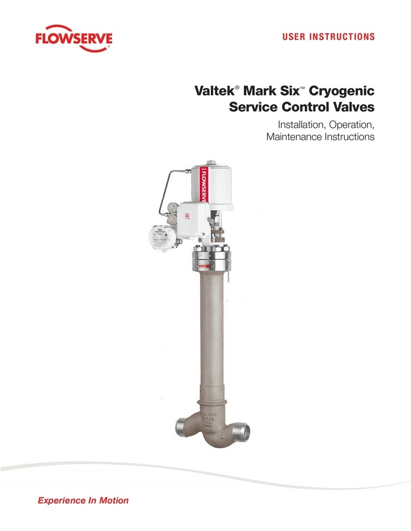
Valtek Mark Six Cryogenic
Service Control Valves
Unpacking
1. Beforeinstallation,checkthepackinglistagainstthe
materials received. Lists describing the valve and
accessories are included with each valve.
2. When lifting valve from shipping container, position
liftingstrapstoavoiddamagetotubingandmounted
accessories. Most valves may be lifted by the
actuator lifting ring. If one is not provided use lifting
straps around yoke legs to lift valve.
3. In the event of shipping damage, contact your ship-
per immediately.
4. Should any problem arise, contact your Valtek Con-
trol Products representative.
Installation
Mark Six valves with vented plugs should always be
mounted with the extension and actuator within 15°of
vertical. MarkSixvalvesusingspring-energizedTeflon
plug head seals may be mounted horizontally.
1. Before installation, clean the line of all dirt, scale,
welding chips and other foreign material.
2. Check flow direction to be sure the valve is installed
correctly. Flowshouldbeovertheplugforfail-closed
valves,andundertheplugforfail-openvalves. Flow
direction is indicated by an arrow on the bonnet
flange.
3. Provide proper overhead clearance above the ac-
tuator to allow for actuator removal and trim inspec-
tion,shoulditbenecessary. Disassemblyclearance
dependsonthe lengthofthecoldbox extensionand
the valve size. To estimate required clearance, add
the length of the extension to the appropriate dis-
tance recommended for the particular valve size.
GENERAL INFORMATION
The following instructions are designed to assist in
unpacking, installing and performing maintenance
required for the Valtek®Mark Six cryogenic service
control valves.
Thispublication doesnotcontaininformation oninstall-
ing,maintaining,troubleshooting,calibrating,andoper-
atingValtekpositioners.RefertotheappropriateValtek
Control Products Installation, Operation, Maintenance
Instruction when this information is required.
To avoid possible injury to personnel or dam-
age to valve parts, WARNING and CAUTION
notes must be strictly adhered to. Modifying
this product, substituting nonfactory parts, or
inferiorparts,orusingmaintenanceprocedures
otherthanoutlined could drastically affectper-
formance, void product warranties and be haz-
ardous to personnel and equipment.
The Valtek Mark Six is a globe style, single seat, top
entry valve with a fabricated cold box extension for use
in cryogenic applications down to minus 423°F. Body
weight is kept to a minimum to reduce boil-off on valve
cool-down. The extension design permits easy access
andremoval ofthevalve trimthroughthecoldbox. The
Mark Six utilizes a spring-energized Teflon seal or a
small vent hole through the plug seal to permit only a
small amount of liquefied gas into the bonnet areas
where it vaporizes and provides a vapor barrier be-
tween the liquefied gas and the packing. The pressure
resulting from the vaporization of the liquid keeps any
more liquid from passing into the bonnet area. The
small amount of vaporized liquid is not sufficient to
produce high pressures at shut-down.
6-2
Quick-Check
Prior to startup, stroke the control valve. As the instru-
ment signal pressure is changed, observe the plug
position as shown by the stroke indicator plate.
1. Check for full stroke by making appropriate instru-
ment signal change (such as 3-15, 3-9, or 9-15 psi).
2. Check all air connections for leaks.
3. Evenlytightenpackingnutstoslightlyoverfinger-tight.
CAUTION: Donotovertightenpacking. Thiscan
cause excessive packing wear and high stem
friction which may impede stem movement.
4. After valve has been in operation a short time,
readjust packing to slightly more than finger-tight.
5. Stroke valve to make sure that the valve fails in the
right direction in case of air failure, and that the
combined actions of the controller, positioner and
valve will provide control of the flow.
STARTUP
WARNING: Onvalveswithspring-energizedTeflon
seals, it may take hours or even a day for enough
liquefied gas to pass into the bonnet area to effec-
tively “balance” the pressure across the plug seal.
Intheeventofairfailureinafail-closedvalveduring
this time, fluid forces may tend to open the valve
ratherthancloseit becausetheeffectivearea ofthe
plug seal is greater than the effective seat area.
Once enough vapor is in the bonnet area, the pres-
sures on each side of the plug equalize and normal
valve operation results. Valves with spring-ener-
gized Teflon seals, are available and do not require
time to “balance” the pressure across the plug
head.
Troubleshooting
If difficulty is suspected with the control valve, proceed
as follows:
1. Make sure valve has sufficient air supply.
2. Check for air leaks anywhere in supply and instru-
ment signal systems and on valve positioner.
3. Make sure packing isn’t too tight by loosening gland
flange nuts and retightening to just over finger-tight.
4. Push the restriction orifice cleanout plunger on the
positioner several times.
5. Checkforstemfreezingcausedbythecondensation
of atmosphere moisture at the exit of the stem from
the packing. If this occurs, a longer extension may
be required or the temperature surrounding the
packing box should be raised.
VALVE MAINTENANCE
The Valtek Mark Six top entry design allows for easy
trim inspection and service without removing the valve
body from line or the insulation to get at the bonnet.
Routine maintenance consists of tightening the gland
flange nuts to compensate for packing wear. Do not
overtightenpackingnuts,sincethiswillshortenpacking
life and may prevent smooth valve performance.
DISASSEMBLY AND REASSEMBLY
WARNING: Depressurize the line to atmospheric
pressure and drain all fluids before working on the
valve. Failure to do so can cause serious injury.
Disassembling the Actuator
1. Fully retract plug until stroke indicator is pointing to
the open position.
2. Remove the bonnet bolts and lift the actuator, bon-
net and plug out of the valve.
CAUTION: The plug head seals may cause the
plug to bind in the body, making it difficult to
remove the actuator plug assembly. To remove
the plug, apply air to the top of the piston,
moving the cylinder and bonnet away from the
plughead. Placesoft(preferablewood)blocking
of equal thickness in at least three positions
between the body and the bonnet. Apply air
underneath the piston to retract the plug.
3. Lift the plug carefully out of the body. Any scraping
parts while removing the plug may cause damage.
Heavy actuators may require a hoist. If the actuator
is not equipped with a lifting ring, use lifting straps
around the yoke legs.
Disassembling the Plug from the Actuator
1. Loosen the stem clamp.
2. Loosen the gland flange.
3. Remove the yoke clamp (or yoke bolts if used).
4. Rotate the actuator in a counterclockwise direction
to disengage the plug stem from the actuator stem.
CAUTION: Toavoidscoringguidesandstem,do
notturnplugsteminbonnet. Flatsaremachined
on the plug stem so it can be held with a wrench.
5. Carefullyremoveplugbypullingitthroughthe bonnet.
6. Push out packing and guides from the bottom of the
bonnet, using a dowel.
7. Inspectguidesforscratchesand scoring. Damaged
guides should be replaced and new packing should
be used upon reassembly.
Replacing the Soft Seat
1. Disassembling the plug.
NOTE: Plug sizes up to 1 1/2 inch use a threaded
plugheaddesignthatclampsthesoftinsertandplug
insertretainerbetweentheplugheadandplugstem.
Disassembletheplug byscrewingtheplugheadout
Valve Size 1/2, 3/4, 1 11/2,2346810
Recommended 3 5 6 8 10 13 14
Distance
Disassembly Clearance (inches)
6-3
oftheplug stem. A rodmaybeinsertedintothehole
drilled through the plug head to facilitate removal.
Plugs above 2 inch use a bolted design that clamps
thesoftinsertbetween theplugheadandplug stem.
Disassemble the plug by removing the cap screws.
2. Clean all parts.
3. Using a new elastomeric insert, reassemble soft
seat components as shown.
NOTE: On small threaded plug heads, make sure
the plug head is screwed in tightly to compress the
soft insert between the plug insert retainer and the
plug head. A self-locking insert prevents the plug
head from working loose.
Plug Stem
Self Locking Insert
Plug Insert Retainer
Soft Insert
Plug Head
Cap Screw
Figure 1: Plug Head Comparision
Figure 2: Plug Seal Comparision Figure 3: Body Subassembly
Bolted Plug Head
Threaded
Plug Head
Spring-energized
Liquid Seal Plug Vented Plug
Upper
Guide
Packing
Bonnet
Flange
Bolting
Bonnet
Gasket
Bonnet
Packing
Spacer
Lower
Guide
Body Plug Seal
Plug
6-4
Inspecting the Screwed-in Seat Ring
1. Unscrew seat ring using a seat ring assembly tool.
NOTE: Flatsaremachinedonthe tool so a wrench
may be used to turn the seat ring. Assembly tool
supports are sometimes needed to keep the as-
sembly tool aligned properly in the seat ring.
2. Ifnecessary, remachinetheseatsurface. Theseat
angle on the seat ring is 33 degrees.
CAUTION: Insure concentricity of seating sur-
face with the outside diameter of the seat ring.
3. Install seat ring using a seat ring assembly tool.
Reassembly of Mark Six
1. Install a new bonnet gasket.
2. Carefullylower plugasfaras itwillgointothebody.
3. Slidethebonnetactuatorassemblyoverplugstem.
4. Insert guides and packing into the bonnet.
5. Place the gland flange onto the plug stem.
6. Screw the actuator stem onto the plug stem by
rotating the actuator in a clockwise direction.
CAUTION: Do not allow plug to rotate. Leave
two or three threads exposed for air-to-close
valves. For air-to-open valves, screw the plug
stem as far as it will go into the actuator stem.
7. Assemble yoke clamp or tighten the yoke bolts.
8. Cycle the valve to retract the plug.
9. Theplugheadseals,whenused,makeitnecessary
to drive the plug into the body using the actuator.
Partiallyboltdown the bonnet flangeandsupplyair
to upper actuator port to extend the plug. Repeat
operation, if necessary, to bring bonnet fully down
into the body.
10. Tighten two opposing bonnet bolts one-sixth turn.
Tighten all bonnet bolts one-sixth turn at a time,
alternating between opposing bolts. Firmly tighten
all nuts evenly and completely, using full wrench
force to compress the gasket and seat the bonnet
metal-to-metal in the body. Proper tightness re-
quires considerable force; however, the bottoming
of the parts metal-to-metal can easily be felt
through the wrench.
CAUTION: Insufficient tightening will result in
improper gasket compression.
11. Adjust stem engagement for air-to-open valves
only, using the following procedure.
NOTE: Proper stem engagement is essential on
air-to-open valves to provide stiff, stable operation
as the valve throttles near the seat.
Cycle the valve to closed position. Observe plug
positionasshownbythestrokeindicatorplate. This
position is the bottom of the actuator piston stroke.
Cyclethevalvetoopenposition. Screwtheplugout
of the actuator one-half turn. Cycle the valve to
closed position. Observe the plug position as
indicated by the stroke plate. Repeat this proce-
dure, comparing plug position each time until the
indicated plug position is about 1/8 inch above the
initial or bottom position. This procedure must be
followed to assure stiff stable operation as well as
tight shutoff. Tighten all nuts evenly and com-
pletely, using full wrench force to compress the
gasket and seat the bonnet metal-to-metal in the
body. Proper tightness requires considerable
force;however,thebottomingofthepartsmetal-to-
metal can easily be felt through the wrench.
12. Tighten the stem clamp.
13. Tighten packing nuts to slightly over finger-tight.
14. Adjust stroke indicator position to indicate closed
position when valve is closed.
Removing Actuator, Including Yoke
(Without Disassembling the Valve Body
Subassembly)
1.Fully retract the plug until the stroke indicator is
pointing to the open position.
2.Loosen the stem clamp.
3.Loosen the gland flange.
4.Remove the yoke clamp (or yoke bolts if used).
5.Turn actuator completely off the plug and bonnet.
CAUTION: Do not allow the plug stem to rotate.
Flats are machined on the stem so it may re-
quireahoist. Ifalifting ringisnotprovided,use
lifting straps around the yoke legs.
Reassembling Actuator, Including Yoke
1.Lift the plug off the seat and turn the actuator onto
the plug. On air-to-open valves screw the actuator
stem onto the plug stem as far as it will go. On air-
to-close valves, leave two or three threads exposed.
CAUTION: Do not allow the plug to turn on the
seat at any time. Do not turn the plug in the
bonnet. Flatsaremachinedontheplugstemso
it can be held with a wrench.
2.Assemble yoke clamp or tighten yoke bolts.
3.Adjust the stemengagement for air-to-open valves
only, according to the procedure outlined in the
“Reassembly of Mark Six” instructions, step 11.
4.Cycle the valve to closed position.
5.Slide the stem clamp on the actuator stem so
pointer indicated “closed” on the stroke plate.
6.Tighten the stem clamp.
7.Tightentheglandflangenutsevenlytoslightlyover
finger-tight.
Other Flowserve Control Unit manuals

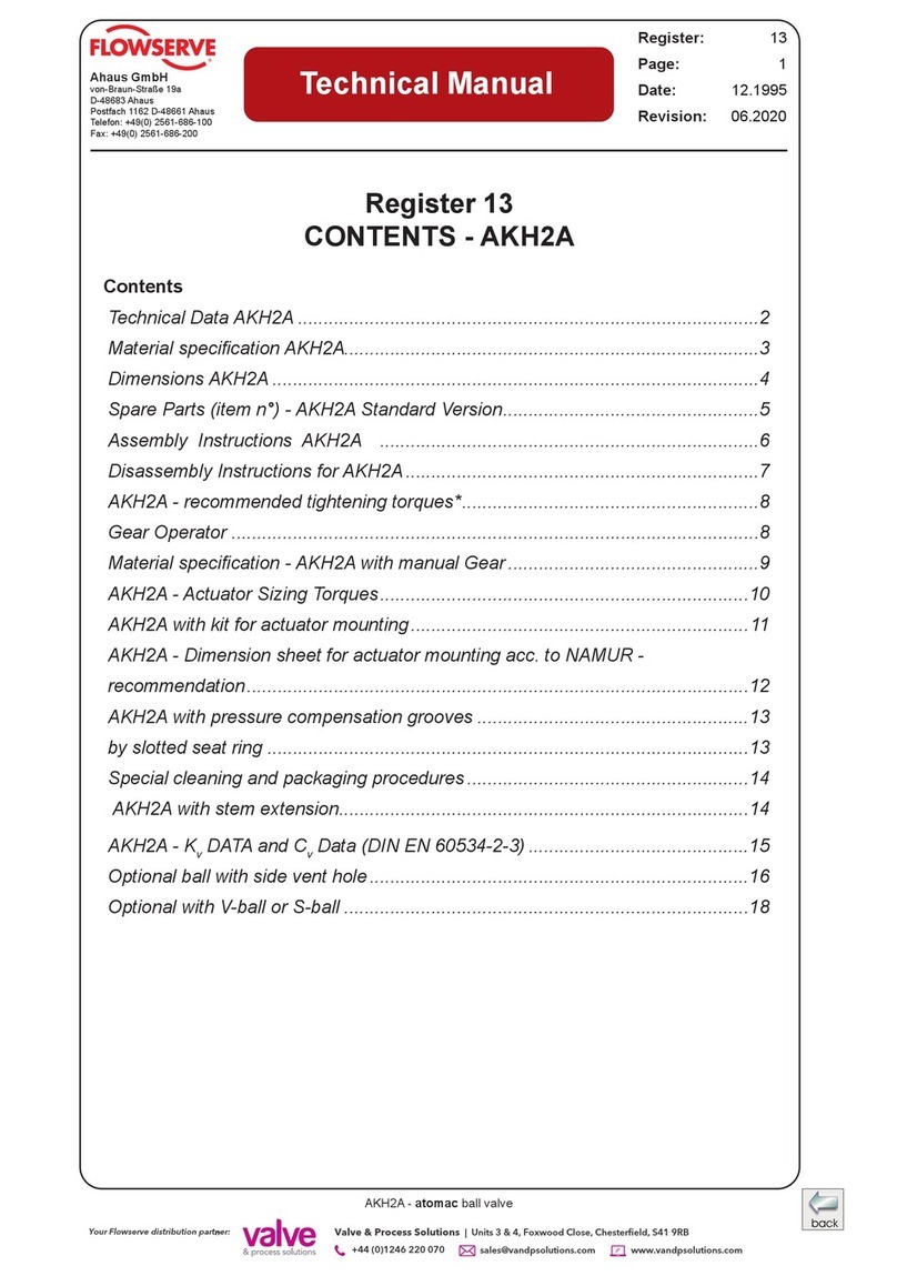
Flowserve NAF-Setball User manual

Flowserve

Flowserve NAF-Setball User manual

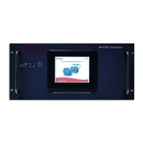
Flowserve 94 Series Manual

Flowserve

Flowserve 94 Series Manual

Flowserve NAF ProCap Installation instructions

Flowserve

Flowserve NAF ProCap Installation instructions

Flowserve T4E-1 User manual

Flowserve

Flowserve T4E-1 User manual

Flowserve 818 Series Manual

Flowserve

Flowserve 818 Series Manual

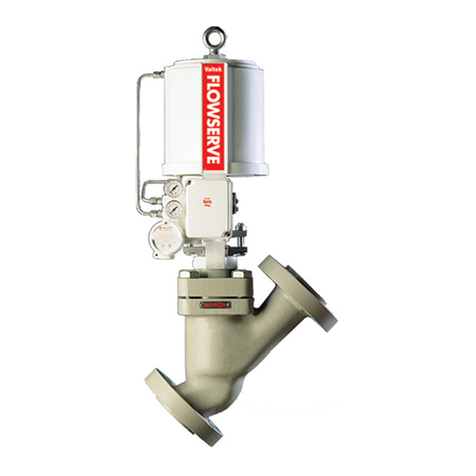
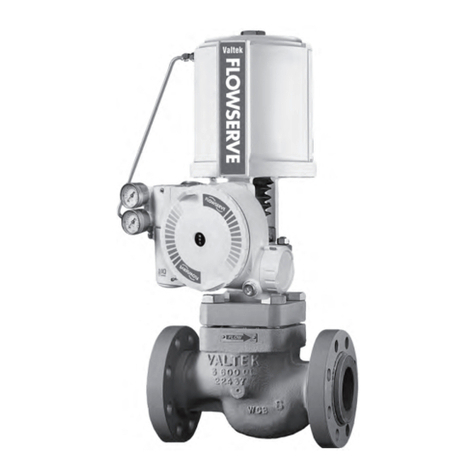
Flowserve Valtek Mark Six Guide

Flowserve

Flowserve Valtek Mark Six Guide

Flowserve atomac AKH7 Series User manual

Flowserve

Flowserve atomac AKH7 Series User manual

Flowserve Valdisk 150 Manual

Flowserve

Flowserve Valdisk 150 Manual

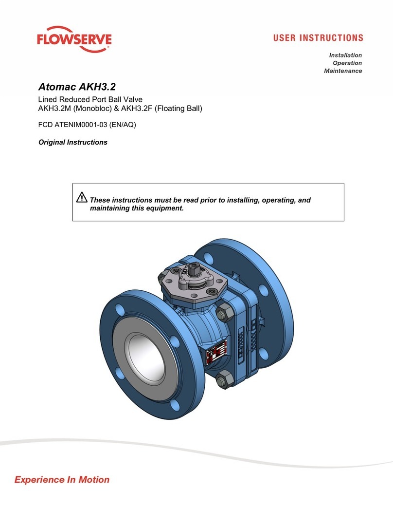
Flowserve Atomac AKH3.2 User manual

Flowserve

Flowserve Atomac AKH3.2 User manual

Flowserve NAF Duball DL User manual

Flowserve

Flowserve NAF Duball DL User manual

Flowserve Gestra GAV 56F User manual

Flowserve

Flowserve Gestra GAV 56F User manual

Flowserve Worcester V-Flow 51 Series User manual

Flowserve

Flowserve Worcester V-Flow 51 Series User manual

Flowserve Nordstrom Series Operating instructions

Flowserve

Flowserve Nordstrom Series Operating instructions

Flowserve Valtek FlowTop V746 User manual

Flowserve

Flowserve Valtek FlowTop V746 User manual

Flowserve AKH2A User manual

Flowserve

Flowserve AKH2A User manual

Flowserve AKH2 User manual

Flowserve

Flowserve AKH2 User manual

Flowserve Valtek Guide

Flowserve

Flowserve Valtek Guide

Flowserve NAF Trunnball DL Series User manual

Flowserve

Flowserve NAF Trunnball DL Series User manual

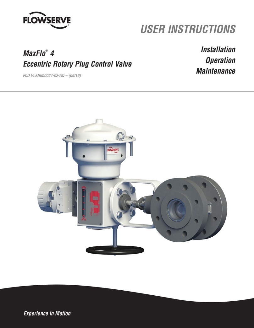
Flowserve MaxFlo4 User manual

Flowserve

Flowserve MaxFlo4 User manual

Flowserve Valtek Valdisk Guide

Flowserve

Flowserve Valtek Valdisk Guide

Flowserve APS1 Manual

Flowserve

Flowserve APS1 Manual

Flowserve Valtek GS User manual

Flowserve

Flowserve Valtek GS User manual

Flowserve Valtek CavControl Trim Guide

Flowserve

Flowserve Valtek CavControl Trim Guide

Flowserve Worcester 13 Series User manual

Flowserve

Flowserve Worcester 13 Series User manual

Popular Control Unit manuals by other brands

Automated Logic LGE Technical instructions

Automated Logic

Automated Logic LGE Technical instructions

Siemens SINUMERIK 840D sl Programming manual

Siemens

Siemens SINUMERIK 840D sl Programming manual

CLA-VAL 50B-4KG1 Installation, operation and maintanance manual

CLA-VAL

CLA-VAL 50B-4KG1 Installation, operation and maintanance manual

Mitsubishi Electric FX-USB-AW user manual

Mitsubishi Electric

Mitsubishi Electric FX-USB-AW user manual

Gifas-electric TrafficLED installation instructions

Gifas-electric

Gifas-electric TrafficLED installation instructions

Clack Water Specialist CI Programming manual

Clack

Clack Water Specialist CI Programming manual

Pickering SYSTEM 10 user manual

Pickering

Pickering SYSTEM 10 user manual

AUDAC EPA104 user manual

AUDAC

AUDAC EPA104 user manual

Silicon Laboratories EMBER EM358 series Reference manual

Silicon Laboratories

Silicon Laboratories EMBER EM358 series Reference manual

Fukuda Denshi HR-800 Service manual

Fukuda Denshi

Fukuda Denshi HR-800 Service manual

Energeeks EG-MODPERS001 Quick installation guide

Energeeks

Energeeks EG-MODPERS001 Quick installation guide

Edwards CTM Installation sheet

Edwards

Edwards CTM Installation sheet

NuTone PM44 instructions

NuTone

NuTone PM44 instructions

Continental Disc Corporation SANITRX HPX installation instructions

Continental Disc Corporation

Continental Disc Corporation SANITRX HPX installation instructions

Sleipner ECU user manual

Sleipner

Sleipner ECU user manual

b&t BW16-Kit specification

b&t

b&t BW16-Kit specification

Emerson Fisher HP instruction manual

Emerson

Emerson Fisher HP instruction manual

Simplex Foundation Series Operation guide

Simplex

Simplex Foundation Series Operation guide

manuals.online logo
manuals.online logoBrands
  • About & Mission
  • Contact us
  • Privacy Policy
  • Terms and Conditions

Copyright 2025 Manuals.Online. All Rights Reserved.