manuals.online logo
Brands
  1. Home
  2. •
  3. Brands
  4. •
  5. Flowserve
  6. •
  7. Control Unit
  8. •
  9. Flowserve Valtek Guide

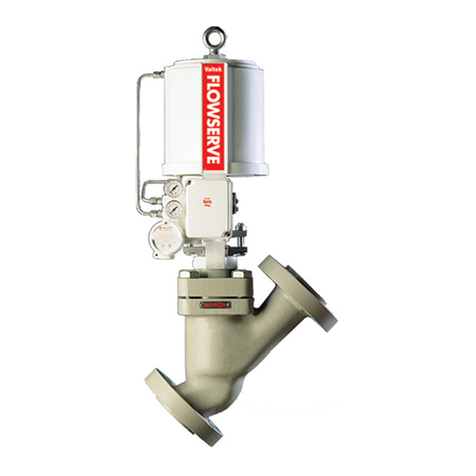
Flowserve Valtek Guide

Valtek No. 49024 14-1
GENERAL INFORMATION
The following instructions are designed to assist in
installing, disassembling and troubleshooting Valtek®
globe valves equipped with extended bonnets. Product
users and maintenance personnel should thoroughly
review this bulletin in conjunction with Installation, Op-
eration Maintenance Instructions 1 (Mark One and Two
Control Valves) before installing, operating or perform-
ing any maintenance on the valve.
To avoid possible injury to personnel or dam-
age to valve parts, WARNING and CAUTION
notes must be strictly adhered to. Modifying
this product, substituting nonfactory parts, or
using maintenance procedures other than out-
lined could drastically affect performance and
be hazardous to personnel and equipment, and
may void existing warranties.
Five bonnet designs exist: two extended bonnet de-
signs (one-piece bonnets) and three bonnet extension
designs in which the extension clamps to a standard
bonnet. This bulletin presents instructions and sec-
tioned-view drawings for all five designs.
Installation
Valtek valves equipped with extended bonnets are
designed to be installed vertically. This ensures a stag-
nated, moderate temperature vapor barrier inside the
bonnet, protecting the packing from the process.
CAUTION: Do not insulate the extended bonnet or
bonnet extension. Although thermal insulation may
be installed on the valve body and adjoining piping
for extreme temperature service, the extended bon-
net operates in hot service by radiating heat to
atmosphere, and in cryogenic service by collecting
heat from atmosphere. Insulating the bonnet will
affect performance and possibly damage the valve.
DISASSEMBLY AND REASSEMBLY
Disassembling One-piece or One-piece
Cryogenic Extended Bonnets
To disassemble valves equipped with extended bon-
nets, refer to Figures 1 and 2 then proceed as follows:
WARNING: Depressurize line to atmospheric pres-
sure, drain all fluids and decontaminate the valve (if
caustic or hazardous materials are present). Failure
to do so can cause serious injury.
1. Remove bonnet flange bolts or nuts.
2. Remove the entire actuator/bonnet assembly by
lifting it straight out of the body.
CAUTION: Heavy assemblies may require a
hoist. Attach lifting straps to actuator yoke legs.
3. Loosen the actuator stem clamp.
4. Remove the packing box bolting.
WARNING: Process fluid may be trapped in the
extended bonnet; therefore, be extremely cau-
tious when removing the plug from the bonnet.
Failure to do so can cause serious injury or
damage to equipment.
5. Remove yoke bolting, clamps, and half rings
(if present).
6. Remove the actuator by unscrewing the plug and
bonnet from the actuator stem. To avoid galling the
plug stem, the bonnet must be turned with the plug
when unscrewing it from the actuator. This ensures
the plug does not turn in relation to the packing box,
which may cause plug stem damage.
WARNING:Donotallowtheplugorbonnettofall
during removal from the actuator. Serious per-
sonal injury or valve damage may result.
7. Remove the bonnet flange from the bonnet.
8. Pull the plug carefully through the packing box.
Valtek Extended Bonnets
IM014 Extended Bonnets.p65 8/21/01, 2:14 PM1
14-2 Flowserve Corporation, Valtek Control Products, Tel. USA 801 489 8611
9. If the one-piece, cryogenic bonnet’s lower stem
guide requires replacement, remove the lower
guide by filing or grinding away the six peened-
points around the guide. File away only the material
necessary to free the guide.
CAUTION: The cryogenic bonnet is designed for
the lower guide to be removed a maximum of
three times (or 18 peened-points). Unnecessary
grinding of material from the bonnet may result
in shorter bonnet life.
10. To replace the packing or packing box configura-
tion, push out the upper stem guide, packing, pack-
ing spacer and stem follower (and lower stem guide
on non-cryogenic extended bonnets) with a dowel of
the same approximate diameter as the plug stem.
Reassembling One-piece or One-piece
Cryogenic Extended Bonnets
To reassemble valves equipped with extended bon-
nets, refer to Figures 1, 2 and 3 then proceed as follows:
1. If a one-piece, cryogenic bonnet’s lower stem guide
has been removed, push a replacement into the
bore and peen six-places in the 1
/32-inch deep
groove around the guide. Peen only enough to hold
the guide in place.
Figure 1: One-piece Extended Bonnet
Note: Item numbers correspond directly to the valve's bill of material. Refer to the bill of material for specific part numbers.
Upper
Stem Guide
(Item No. 87)
Packing
(Item No. 88)
Extended Bonnet
(Item No. 40)
Plug
(Item No. 50)
Bonnet Flange
(Item No. 70)
Lower
Stem Guide
(Item No. 83)
Seat Retainer
(Item No. 30)
Seat Ring
(Item No. 20)
Gland Flange
(Item No. 80)
Yoke Clamp
(Item No. 76)
Yoke Clamp
Bolting
(Item No. 107/118)
Packing Spacers
(Item No. 94)
Bonnet Flange
Bolting
(Item No. 108/114)
Bonnet Gasket
(Item No. 58)
Body
(Item No. 1)
Seat Ring
Gasket
(Item No. 55)
IM014 Extended Bonnets.p65 8/21/01, 2:14 PM2
14-3
Flowserve Corporation, Valtek Control Products, Tel. USA 801 489 8611
CAUTION: Do not distort the guide by using
excessive force when peening.
2. If the packing has been removed and will be re-
placed with packing other than square packing,
reinstall the lower guide (in non-cryogenic, ex-
tended bonnets only), 1/8-inch spacer, tube spacer,
additional spacers and lower packing and lube
spacer, the upper packing, and upper stem guide. If
changing the packing box configuration, refer to
Figure 3 for different packing arrangements.
3. Reinsert the plug stem into the packing box, being
careful not to score the stem or the guides. If square
packing is being installed, slip it over the plug stem
and into the packing box. Tap it in place with a brass
tamping bar, being careful to not damage the plug
stem or packing box wall.
4. Replace the bonnet flange on the bonnet.
5. Turn the actuator back onto the plug, making sure
the gland flange is in place before screwing the plug
stem into the actuator stem. Be certain to turn the
plug and bonnet in unison to avoid galling or
scratching. Leave approximately two to three plug
stem threads exposed.
6. Attach the yoke clamps and bolting, and the gland
flange bolting. Tighten the packing box nuts to
slightly more than finger-tight.
Figure 2: One-piece Cryogenic Bonnet
Note: Item numbers correspond directly to the valve's bill of material. Refer to the bill of material for specific part numbers.
Upper
Stem Guide
(Item No. 87)
Packing
(Item No. 88)
Packing Spacer
(Item No. 94)
Extended Bonnet
(Item No. 40)
Plug
(Item No. 50)
Bonnet Flange
(Item No. 70)
Lower
Stem Guide
(Item No. 83)
Seat Retainer
(Item No. 30)
Seat Ring
(Item No. 20)
Gland Flange
(Item No. 80)
Yoke Clamp
Bolting
(Item No. 107/118)
Yoke Clamp
(Item No. 76)
Bonnet Flange
Bolting
(Item No. 108/114)
Bonnet Gasket
(Item No. 58)
Body
(Item No. 1)
Seat Ring
Gasket
(Item No. 55)
IM014 Extended Bonnets.p65 8/21/01, 2:14 PM3
14-4 Flowserve Corporation, Valtek Control Products, Tel. USA 801 489 8611
Figure 3: Packing Configurations
Extended Twin "V"
With Purge
Extended Twin "V"
Extended "V"
Vacuum Seal Twin "V"
With Purge
Extended Square
Extended Twin Square
With Purge
Extended Twin Square
IM014 Extended Bonnets.p65 8/21/01, 2:14 PM4
14-5
Flowserve Corporation, Valtek Control Products, Tel. USA 801 489 8611
Figure 4: Bolted Extension Figure 5: Bolted Flange Extension
Bonnet
(Item No. 40)
Extension
Bonnet
(Item No. 41)
Bolting
(Item no. 110)
Bonnet
Extension
Gasket
(Item No. 60)
Bolting
(Item no. 110)
Bonnet
Extension
Gasket
(Item No. 60)
Extension Bonnet
(Item No. 41)
Half Ring
(Item No. 13)
Bonnet
(Item No. 40)
Flange
(Item No. 73)
Note: Item numbers correspond directly to the valve's bill of material. Refer to the bill of material for specific part numbers.
CAUTION: Do not overtighten packing. This can
cause excessive packing wear and stem friction
which may impede stem movement.
7. After installing a new seat gasket, the seat ring, seat
retainer and a new bonnet gasket, lower the actua-
tor/bonnet assembly squarely into body. Be careful
to not scratch or gall plug as it enters the body.
8. Install bonnet flange bolting to finger-tightness.
Apply air pressure above the piston to seat the plug
in the seat ring. Tighten each bonnet bolt about 1/6
(one flat) of a turn at a time in a clockwise direction
around the bonnet flange. Firmly tighten all bolts
evenly and completely to compress the bonnet
gasket until the bonnet is seated metal-to-metal in
the body. Proper tightness is achieved when metal-
to-metal resistance can be felt with the wrench.
CAUTION: If the bolting is insufficiently tight-
ened, the seat ring gasket will not have enough
compression, resulting in leakage. Overtighten-
ing beyond the point of metal-to-metal resis-
tance may damage interior valve parts.
9. The amount the plug stem is screwed into the
actuator stem is not particularly important on air-to-
close valves as long as the plug fully contacts the
seat when the valve is closed. It is necessary only to
leave two to three threads exposed. For correct plug
engagement on air-to-open valves, screw the plug
stem into the actuator stem as far as possible. Apply
air pressure above the piston to drive it to the bottom
of the actuator cylinder. Back the plug stem out of
the actuator stem until the plug just touches the seat
ring. Apply air under the piston to lift the plug off the
seat and back the plug stem out of the actuator stem
exactly one complete turn.
10. Apply air over the piston to seat the plug. With the
stem clamp adjusted to the “closed”position of the
stroke indicator plate, tighten stem clamp bolting.
Disassembling Bonnet Extensions
To disassemble valves equipped with bonnet extensions,
refer to Figures 4, 5, 6 and 7 then proceed as follows:
WARNING: Depressurize line to atmospheric pres-
sure, drain all fluids and decontaminate the valve (if
caustic or hazardous materials are present). Failure
to do so can cause serious injury.
1. Remove bonnet flange bolts or nuts.
2. Remove the entire actuator/bonnet extension as-
sembly –including the bonnet and plug –by lifting it
straight out of the body.
CAUTION: Heavy assemblies may require a
hoist. Attach lifting straps to actuator yoke legs.
3. Loosen the actuator stem clamp.
4. Remove packing box bolting.
5. Remove the yoke bolting, clamps and half rings (if
present).
6. Remove the actuator by unscrewing the plug and
bonnet in unison from the actuator stem. Unscrew-
ing the plug and bonnet together prevents damage
to the plug stem and packing box wall.
WARNING:Donotallowtheplugorbonnettofall
during removal from the actuator. Serious per-
sonal injury or valve damage may result.
7. Pull the plug carefully through the packing box and
bonnet.
WARNING: Process fluid may be trapped in the
bonnet extension; therefore, be extremely cau-
tious when removing the plug from the bonnet
and bonnet extension.
IM014 Extended Bonnets.p65 8/21/01, 2:14 PM5
14-6 Flowserve Corporation, Valtek Control Products, Tel. USA 801 489 8611
8. Remove the bonnet connecting bolts, extension
clamps or flanges and half-rings (see Figures 4, 5,
6 and 7) and associated bolting. The bonnet flange
may now be removed, if desired.
9. Pull apart the bonnet and bonnet extension and
remove stem guides, packing, and packing spacers
from both halves of the packing box.
10. Remove the bonnet extension gasket from gasket
groove on the bottom face of the bonnet extension.
Reassembling Bonnet Extensions
To reassemble valves equipped with bonnet exten-
sions, refer to Figures 3, 4, 5, 6 and 7 then proceed as
follows:
1. Clean the gasket seating surfaces on the bonnet
and bonnet extension.
2. Insert lower stem guide and packing spacer into the
bonnet.
3. In clamp-on extensions, place a joint packing
spacer in the bonnet. This spacer should be cen-
tered at the joint between the bonnet and bonnet
extension.
NOTE: Late model extensions do not have joint
packing spacers. Packing spacers only need to be
installed up to the packing.
4. Making sure the new bonnet extension gasket is
properly seated in the gasket groove on the bottom
face of the bonnet extension, slip the bonnet exten-
Figure 6: Clamped Bonnet Extension
Note: Item numbers correspond directly to the valve's bill of material. Refer to the bill of material for specific part numbers.
Gland Flange
(Item No. 80)
Upper Stem Guide
(Item No. 87)
Packing
(Item No. 88)
Bonnet Extension Clamp
(Item No. 72)
Bonnet Extension
Gasket
(Item No. 60)
Bonnet Flange Bolting
(Item No. 108/114)
Bonnet Flange
(Item No. 70)
Bonnet Gasket
(Item No. 58)
Lower
Stem Guide
(Item No. 83)
Seat Retainer
(Item No. 30)
Seat Ring
(Item No. 20)
Yoke Clamp
(Item No. 76)
Yoke Clamp Bolting
(Item No. 107/118)
Yoke Half Rings
(Item No. 12)
Bonnet Extension
(Item No. 41)
Packing Spacer
(Item No. 95)
Clamp Bolting
(Item No. 110/120)
Joint Packing Spacer
(Item No. 94)
Bonnet
(Item No. 40)
Packing
Spacer
(Item No. 93)
Plug
(Item No. 50)
Body
(Item No. 1)
Seat Ring
Gasket
(Item No. 55)
IM014 Extended Bonnets.p65 8/21/01, 2:14 PM6
14-7
Flowserve Corporation, Valtek Control Products, Tel. USA 801 489 8611
sion over the joint packing spacer and mate the
bottom face of the bonnet extension with the top
face of the bonnet.
5. After making sure the bonnet flange is in place,
reinstall the connecting bolts, extension clamps or
flanges and associated bolting. When using
flanges, make sure the flange half-rings are posi-
tioned as shown in Figure 5 or 7, depending on the
extension configuration. At this point, the bolting
should only be just more than finger-tight.
6. Reinstall remaining packing spacer(s), new pack-
ing, and upper stem guide. Install lubricator, if
required.
7. Insert plug stem through bonnet and bonnet exten-
sion, being careful not to score the stem or guides.
8. After reinstalling the two yoke half-rings on the
bonnet extension and making sure the gland flange
is in place, turn the actuator back onto the plug.
Leave approximately two or three plug stem threads
exposed.
9. Attach the yoke clamps and gland flange bolting.
Tighten packing box nuts to slightly over finger-tight.
CAUTION: Do not over-tighten packing. This
can cause excessive packing wear and stem
friction which may impede stem movement.
10. After installing new seat and bonnet gaskets, lower
the actuator/bonnet assembly squarely into the
body. Be careful not to scratch or gall the plug as it
enters the body.
11. Install bonnet flange bolting to finger-tightness.
Apply air pressure above the piston to seat the plug
in the seat ring. Tighten each bonnet bolt about 1/6
(one flat) of a turn at a time in a clockwise direction
around the bonnet flange. Firmly tighten all bolts
evenly and completely. Compress the bonnet gas-
ket until the bonnet is seated metal-to-metal in the
body. Proper tightness is achieved when metal-to-
metal resistance can be felt with the wrench.
CAUTION: If the bolting is insufficiently tight-
ened, the seat ring gasket will not have enough
compression, resulting in leakage. Overtighten-
ing beyond the point of metal-to-metal resis-
tance may damage interior valve parts.
12. The amount the plug stem is screwed into the
actuator stem is not particularly important on air-to-
close valves. It is necessary only to leave two to
three threads exposed. For correct plug engage-
ment on air-to-open valves, screw the plug stem into
the actuator stem as far as possible. Apply air
pressure above the piston to drive it to the bottom of
the actuator cylinder. Back the plug stem out of the
actuator stem until the plug just touches the seat
ring. Apply air under the piston to lift the plug off the
seat and back the plug stem out of the actuator stem
exactly one complete turn.
13. Apply air over the piston to seat the plug. With the
stem clamp adjusted to the “closed”position of the
stroke indicator plate, tighten stem clamp bolting.
14. After the bonnet flange bolting has been tightened
and the plug adjusted, tighten the extension clamp
or flange bolting so that even pressure on the gasket
and proper alignment of the bonnet and bonnet
extension are maintained.
Figure 7: Bolted Double-flange and Clamp Design
Note: Item numbers correspond directly to the valve's bill of material. Refer to the bill of material for specific part numbers.
Lower Flange
(Item No. 73)
Upper Flange
(Item No. 72)
Flange Half Rings
(Item No. 13)
Bonnet
(Item No. 40)
Bonnet Extension
(Item No. 41) Bolting
(Item No. 110)
Bonnet Extension
Gasket
(Item No. 60)
IM014 Extended Bonnets.p65 8/21/01, 2:15 PM7
FCD VLAIM014-08 © 2001 Flowserve Corporation. Flowserve Corporation, Valtek Control Products, Tel. USA 801 489 8611
Flowserve Corporation has established industry leadership in the design and manufacture of its products. When properly selected, this Flowserve product is designed to perform its intended
function safely during its useful life. However, the purchaser or user of Flowserve products should be aware that Flowserve products might be used in numerous applications under a wide
variety of industrial service conditions. Although Flowserve can (and often does) provide general guidelines, it cannot provide specific data and warnings for all possible applications. The
purchaser/user must therefore assume the ultimate responsibility for the proper sizing and selection, installation, operation and maintenance of Flowserve products. The purchaser/user
should read and understand the Installation Operation Maintenance (IOM) instructions included with the product, and train its employees and contractors in the safe use of Flowserve products
in connection with the specific application.
While the information and specifications presented in this literature are believed to be accurate, they are supplied for informative purposes only and should not be considered certified or
as a guarantee of satisfactory results by reliance thereon. Nothing contained herein is to be construed as a warranty or guarantee, express or implied, regarding any matter with respect
to this product. Because Flowserve is continually improving and upgrading its product design, the specifications, dimensions and information contained herein are subject to change without
notice. Should any question arise concerning these provisions, the purchaser/user should contact Flowserve Corporation at any of its worldwide operations or offices.
For more information, contact:
Flowserve and Valtek are registered trademarks of Flowserve Corporation. For more information about Flowserve, contact www.flowserve.com or call USA 972 443 6500
Regional Headquarters
1350 N. Mt. Springs Prkwy.
Springville, UT 84663
Phone 801 489 8611
Facsimile 801 489 3719
12 Tuas Avenue 20
Republic of Singapore 638824
Phone (65) 862 3332
Facsimile (65) 862 4940
12, av. du Québec, B.P. 645
91965, Courtaboeuf Cedex, France
Phone (33 1) 60 92 32 51
Facsimile (33 1) 60 92 32 99
Quick Response Centers
5114 Railroad Street
Deer Park, TX 77536 USA
Phone 281 479 9500
Facsimile 281 479 8511
104 Chelsea Parkway
Boothwyn, PA 19061 USA
Phone 610 497 8600
Facsimile 610 497 6680
1300 Parkway View Drive
Pittsburgh, PA 15205
USA
Phone 412 787 8803
Facsimile 412 787 1944
Troubleshooting Extended Bonnets
Failure Probable Cause Corrective Action
Leakage through 1. Insufficient compression of 1. Tighten flanges or clamps until leakage stops
clamps or flanges bonnet extension gasket
2. Worn or damaged bonnet extension gasket 2. Disassemble and replace gasket
3. Faulty clamp 3. Replace with bolted or bolted flange extension or
extended bonnet
4. Side loading of the bonnet extension 4. Install valve with extension as vertical as possible
Leakage through 1. Loose packing box bolts 1. Tighten packing box bolts sufficiently to stop leakage
packing box 2. Worn or damaged packing 2. Disassemble and replace packing
3. Dirty or corroded packing box 3. Clean body bore and plug stem, replace packing
Stem motion 1. Overtightened packing 1. Adjust packing box nuts to slightly more than finger-tight
impeded 2. Service temperature is beyond operating 2. Reconfirm service conditions and contact factory
parameters of trim design
3. Inadequate air supply 3. Check for leaks in air supply or instrument signal system;
tighten loose connections and replace leaky lines
4. Malfunctioning positioner 4. Refer to positioner maintenance instructions
Excessive leakage 1. Improperly tightened bonnet flange 1. Refer to Maintenance Instructions 1 for correct tightening
bolting procedure
2. Worn or damaged seat ring 2. Disassemble valve and replace or repair seat ring
3. Worn or damaged seat or bonnet gasket 3. Disassemble and replace gaskets
4. Inadequate actuator thrust 4. Check for adequate air supply to actuator; if supply is
adequate, reconfirm service conditions, contact factory
5. Incorrectly adjusted plug 5. Refer to appropriate step for plug adjustment contained
earlier in this maintenance instructions
6. Improper flow direction 6. Make sure flow direction is always over plug; if incorrect,
change to flow-over
Inadequate Flow 1. Improper plug adjustment limiting stroke 1. Refer to appropriate step for plug adjustment contained
earlier in this maintenance instructions
2. Malfunctioning positioner 2. Refer to positioner maintenance instructions
3. Service conditions exceeding trim design 3. Verify service conditions and consult factory
capacity
Plug slams 1. Incorrect plug adjustment allowing 1. Refer to appropriate step for plug adjustment contained
improper cushion of air between actuator earlier in this maintenance bulletin
piston and yoke
2. Trim sized too large for flow rate 2. Install reduced trim
3. Inadequate air supply 3. Check air supply to actuator; repair leaks and remove any
restrictions in supply line
IM014 Extended Bonnets.p65 8/21/01, 2:15 PM8

Other manuals for Valtek

1

Other Flowserve Control Unit manuals

Flowserve Valtek Three-way Guide

Flowserve

Flowserve Valtek Three-way Guide

Flowserve Durco Sleeveline G4XZ User manual

Flowserve

Flowserve Durco Sleeveline G4XZ User manual

Flowserve FlowTop V726 User manual

Flowserve

Flowserve FlowTop V726 User manual

Flowserve NAF ProCap Installation instructions

Flowserve

Flowserve NAF ProCap Installation instructions

Flowserve Valtek FlowTop V746 User manual

Flowserve

Flowserve Valtek FlowTop V746 User manual

Flowserve Valtek Mark 100 User manual

Flowserve

Flowserve Valtek Mark 100 User manual

Flowserve Gestra GAV 56F User manual

Flowserve

Flowserve Gestra GAV 56F User manual

Flowserve 158 User manual

Flowserve

Flowserve 158 User manual

Flowserve ASG 3 User manual

Flowserve

Flowserve ASG 3 User manual

Flowserve Valtek MegaStream Guide

Flowserve

Flowserve Valtek MegaStream Guide

Flowserve Atomac AKH3.2 User manual

Flowserve

Flowserve Atomac AKH3.2 User manual

Flowserve S25N Manual

Flowserve

Flowserve S25N Manual

Flowserve T4E-1 User manual

Flowserve

Flowserve T4E-1 User manual

Flowserve 035 000 Series Guide

Flowserve

Flowserve 035 000 Series Guide

Flowserve Valtek Tek-Check Guide

Flowserve

Flowserve Valtek Tek-Check Guide

Flowserve ASF User manual

Flowserve

Flowserve ASF User manual

Flowserve FlowTop V726 Installation instructions

Flowserve

Flowserve FlowTop V726 Installation instructions

Flowserve MASTER STATION IV EEP-SN4001 User manual

Flowserve

Flowserve MASTER STATION IV EEP-SN4001 User manual

Flowserve ARK2 User manual

Flowserve

Flowserve ARK2 User manual

Flowserve Valtek Mark Six Guide

Flowserve

Flowserve Valtek Mark Six Guide

Flowserve 13 Series User manual

Flowserve

Flowserve 13 Series User manual

Flowserve MaxFlo4 User manual

Flowserve

Flowserve MaxFlo4 User manual

Flowserve Valtek Mark Six User manual

Flowserve

Flowserve Valtek Mark Six User manual

Flowserve Valtek MaxFlo 4 User manual

Flowserve

Flowserve Valtek MaxFlo 4 User manual

Popular Control Unit manuals by other brands

SMC Networks VJ3000 Installation and maintenance manual

SMC Networks

SMC Networks VJ3000 Installation and maintenance manual

Digilent PmodCLS Reference manual

Digilent

Digilent PmodCLS Reference manual

Victorian Plumbing Arezzo installation guide

Victorian Plumbing

Victorian Plumbing Arezzo installation guide

heatcon! EM 100 Short instructions

heatcon!

heatcon! EM 100 Short instructions

DSE DSE8610 MKII installation instructions

DSE

DSE DSE8610 MKII installation instructions

ABB RELION 650 SERIES installation manual

ABB

ABB RELION 650 SERIES installation manual

Nordson iTrax quick start guide

Nordson

Nordson iTrax quick start guide

urmet domus Sinthesi 1148 manual

urmet domus

urmet domus Sinthesi 1148 manual

Texas Instruments LMZ35003EVM-001 user guide

Texas Instruments

Texas Instruments LMZ35003EVM-001 user guide

Strong Rising SEW290 Technical user guide

Strong Rising

Strong Rising SEW290 Technical user guide

Samson 3353 Original instructions

Samson

Samson 3353 Original instructions

Sanyo Denki F Series instruction manual

Sanyo Denki

Sanyo Denki F Series instruction manual

VIEWEG DV-5325 operating instructions

VIEWEG

VIEWEG DV-5325 operating instructions

iWave iW-RainboW-G54M STM32MP13 Series Hardware user's guide

iWave

iWave iW-RainboW-G54M STM32MP13 Series Hardware user's guide

TAIYO YUDEN EYSMJCS user manual

TAIYO YUDEN

TAIYO YUDEN EYSMJCS user manual

Samson EB 8061 EN TRANSLATION OF ORIGINAL INSTRUCTIONS

Samson

Samson EB 8061 EN TRANSLATION OF ORIGINAL INSTRUCTIONS

Asco 262 Series Installation and maintenance instructions

Asco

Asco 262 Series Installation and maintenance instructions

Pfeiffer Vacuum EVA 016S operating manual

Pfeiffer Vacuum

Pfeiffer Vacuum EVA 016S operating manual

manuals.online logo
manuals.online logoBrands
  • About & Mission
  • Contact us
  • Privacy Policy
  • Terms and Conditions

Copyright 2025 Manuals.Online. All Rights Reserved.