FLTR CSB Series User manual

Tekleen
CSB USERS’
MANUAL

Table of Contents
Subject
Page Number
Introduction
2
Description & Operation
3-4
Technical Data
5-6
Installation
7-8
Filter Assembly
9-11
Periodic Checks
12
Filter Parts
13-14
Filter Controls
15-20
ALL RIGHTS RESERVED, THIS MANUAL AND THE INFORMATION CONTAINED ARE NOT
ALLOWED TO BE USED WITHOUT WRITTEN PERMISSION FROM AUTOMATIC FILTERS
INC.
For more information:

Introduction
General
Automatic Filters Inc. congratulates you for purchasing the CSB Electric self-
cleaning brush filter. This filter now joins the wide family of filters produced and
supplied by Automatic filters Inc. for industrial, municipal water, sewage
systems, and all types of irrigation applications. All products manufactured by
Automatic Filters Inc. are easy to install, use and service and don’t require
special skills to operate them
.
We would like to wish you many years of satisfied service.
For more information:

Description & Operation
Filter Assembly General Description (Figure 1)
The CSB electric self-cleaning brush filter enables high quality filtration at filtering
degrees of 200-4000 micron from different types of fluid sources such as sewage,
reservoirs, rivers, lakes, and wells.
The CSB filter contains the following parts:
1. Inlet 4. Flushing Valve (HYD or Electric)
2. Screen 5. Electric Motor
3. Brush 6. Outlet
Figure 1: Filter Assembly
For more information:

Filter Operation General Description (Figure 2)
Filtration
Water enters the filter through the “Inlet” (1) and passes through the screen (2), which
purifies the water by separating dirt smaller particles from the water. As more water flows
through, dirt builds up on the screen. As dirt builds up on the screen is causing to a
differential pressure between the in let and outlet
Cleaning Process
When the difference in pressure (
P) reaches the preset value on the differential
pressure indicator, or the dwell time between flushing passed. The controller transmits
a signal for a 10 second flushing cycle. The flushing valve (4) opens, pressure is
released from the inner side of the fine screen (2) the electric motor (5) simultaneously
rotates the brushes (3) around its axis. The brushes wipe all the dirt and efficiently clean
the entire internal screen (3) surface.
At the end of the 10 second cycle the flushing valve (4) closes and the operation of the
electric motor (5) is stopped. The filter is now ready for the next cycle,
Figure 2: Filter Assembly
For more information:

Technical Data
Standard Features
•Minimum operating pressure: 3 bar (45 psi)
•Maximum operating pressure: 10 bar (150 psi)
•Clean filter pressure loss: 0.1 bar (2 psi)
•Maximum water temperature: 90°C (200°F)
•Filtration range: 200 - 4000 micron
•Electric motor: 3-phase 0.5 Hp
•Flush water consumption (at minimum working pressure): 70 liters (18.5 gallons)
•Filter housing materials: carbon steel coated with baked on epoxy, or
stainless steel
General Technical Data
Filter Model M3/h GPM Screen Area Sq/ft
CSB 4 100 400 5
CSB 6 200 800 5
CSB 8 300 1,200 5
CSB 10 450 1,800 7
CSB 12 650 2,600 11
CSB 14 1,000 4,000 12.5
CSB 16 1,500 6,000 16
L= 90
O
Connections IL = Inline connections
*Flow rate data are for high quality water at filtration grade of 200 micron.
** Flushing flow rate data are for minimum operational pressure (1 bar / 15 psi).
Filtration Grade Conversion Table
Micron
200 400 800 1500 3000
Mesh
80 40 20 10 5
For more information:

Pressure Loss At 200 Micron
For more information:

Initial Installation & Operation
General
The filter assembly is packed on a wooden platform with all its parts installed.
Installation (Figure 3)
1. Take the filter assembly out of the wood platform.
2. Install the filter assembly to the inlet line and outlet line.
3. Connect a drainpipe to the hydraulic flushing valve outlet opening (at least 80 mm or
3” diameter and no longer then 10m). Confirm that water runs freely out of the
drainpipe.
4. Position the control panel in such a way as to be protected against humidity
and solar radiation.
5. Connect the control panel to the power source.
6. Check that all connections are properly secured.
7. Check that all bolts and nuts on filter periphery are properly tightened and
secured.
Figure 3: Initial Filter Installation
For more information:

Initial Operation
1. Gradually open the inlet valve (make sure that the outlet valve, if installed, is open).
2. Check the filter assembly and its connections for leaks.
3. Perform a flushing cycle by disconnecting the high pressure tube from the
differential pressure indicator (closing of the electrical circuit) – re-connect it
immediately as flushing start.
4. Verify that the motor start spinning clockwise (if the motor spin to the opposite
side, change the connections of the electric phase) and stop after 10 seconds.
5. Verify that the flushing valve opens and closes after 10 seconds.
6. Perform a flushing cycle by pressing the MANUAL FLUSH switches at the control
panel.
7. Perform continues flushing by disconnecting the high-pressure tube from the
differential pressure indicator (closing of the electrical circuit) second flushing will
start without a delay. Re-connect the high pressure tube.
8. When the filter is clean, verify that the differential pressure between inlet and outlet
does not exceed 0.1 bars (1psi)
9. Set the appropriate differential pressure for flushing at the ∆P differential pressure
indicator to 0.5 bar (7 PSI).
WARNING
Take precautions while operating the filter because the filter might enter a flushing mode
automatically, without prior warning.
For more information:

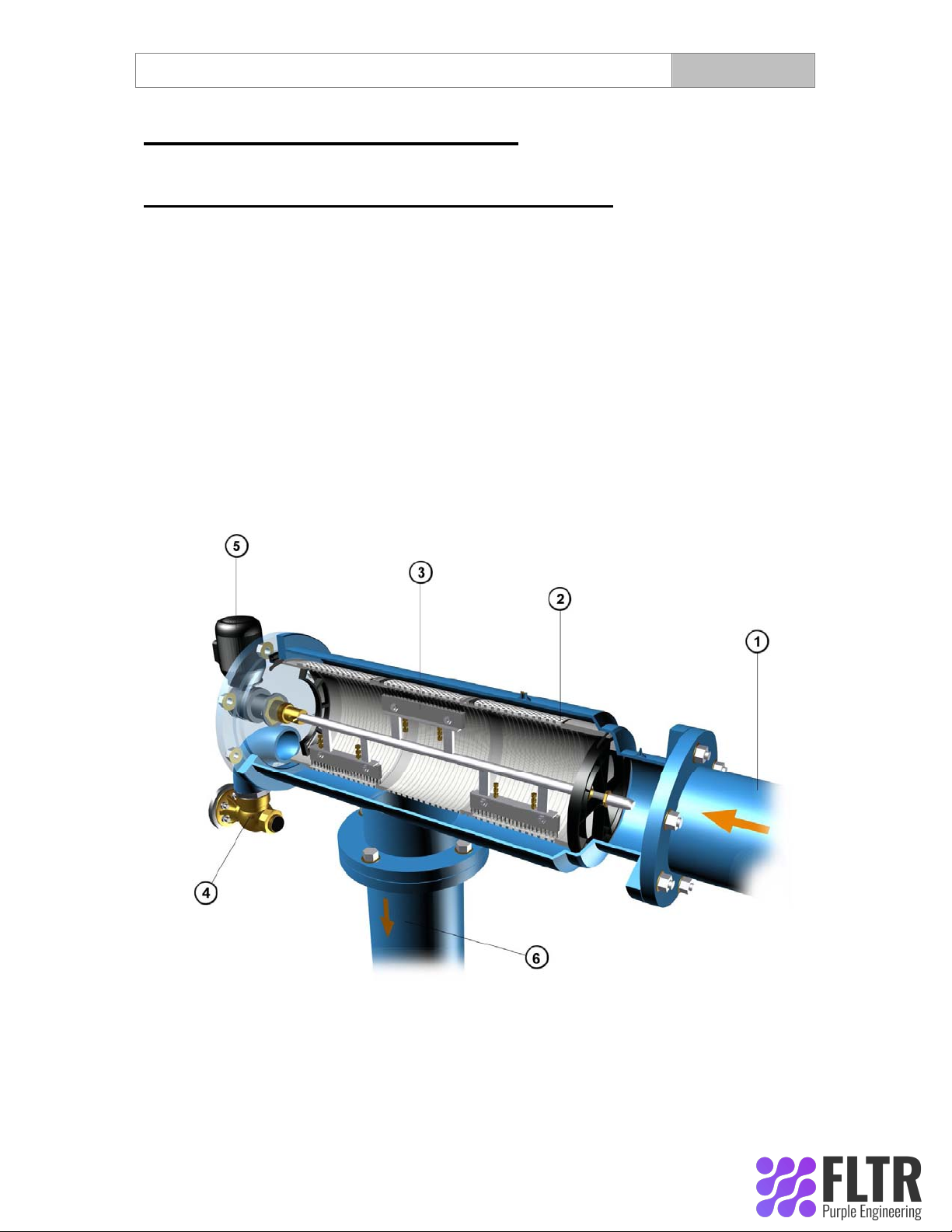
Fine Screen Assembly Removal & Installation (Figure 6 and 7)
1. Close the inlet and the outlet line valves.
2. Set the main switch at the control panel to "0" position.
3. Verify that filter is drained prior to service.
4. Remove the cover with the motor assembly.
5. Pull the screen assembly with the brushes out of the filter housing assembly
6. Than remove the brush assembly.
7. Remove the seals from the old fine screen assembly.
8. Lubricate upper and lower seals with silicon grease.
9. Slide the brush assembly into the screen and only then slide the screen assembly
with the brush assembly into the filter housing assembly.
10. Verify that the straight side of the body seal fits into the groove located in the
cover.
11. Put the cover into its place on the filter. (Take care that the motor’s axis housing is
slide on the brush axis) & install nuts and washers
12. Set the main switch at the control panel to "1" position.
13. Open the inlet and outlet line valves.
14. Perform a flushing cycle by pressing the MANUAL FLUSH switch at the control
panel.
15. Verify that the flushing valves close after 10 flushing cycle and FLUSHING lamp at
the control panel extinguishes and Check for leaks.
WARNING
Take precautions while operating the filter because the filter might enter a flushing mode
automatically, without prior warning.
For more information:

Figure: 4
Figure: 5
For more information:

Figure 6: Brush Removal & Installation
Figure 7: Fine Screen Assembly Removal & Installation
For more information:

Periodical Checks (Figure 8)
Perform yearly Periodical Checks at the beginning of the season, according to the
following instructions:
1. Check the condition of the fine screen assembly. If defective, replace according to
"Fine Screen Assembly Removal & Installation".
2. Check seals condition. Lubricate with silicon grease.
3. Remove the brush according to "brush Removal & Installation" and check the
brushes height. If defective, adjust or replace with a new one.
2. Check condition of the bearings, replace if damaged or deformed.
3. Check existence of grease on the motor axis.
4. Check the filter housing for paint damage and corrosion. If required, clean area with
sandpaper and apply a thin layer of basic + epoxy paint.
5. Check for leaks.
Figure 8: Periodical Checks
For more information:

For more information:

Filter Parts
No. Description
01
Filter body
02
8 mm x ¼” “T” Connection
03
Pressure Difference Indicator
04
Pressure Difference Indicator
05
8 mm x ¼” “T” Connection
06
Solenoid Valve
07
1
/
8
” x 8 mm Control Fitting Connector
08
Washer
09
Nut
10
Lower Screen Bearing
11
Lower Screen Handle
12
Screen O-ring
13
Fine Screen Lower Section
14
Fine Screen Middle Section
15
Fine Screen Upper Section
16
Upper Screen Handle
17
Brush Assembly Axis
18
Brush Unit Tightening Screw
19
Brush Unit
20
U – Ring (body seal)
21
Body Cover
22
2” Connecting Nipple
23
2” Flushing Valve
24
Seal Housing Nut
25
Special Rope Seal
26
Seal Tightening Nut
27
Motor Adaptor
28
Spinning Shaft
29
Shaft Splint
30
Electric Motor
300A
Terminal connections Assembly
300B
Brushes Assembly
For more information:

Appendixes
Appendix 1 – Control Panel & Electrical Wiring Schematic
Drawing
REV. 00
A. PANEL CONTROLS DESCRIPTION.
1. Main switch - Marked [ MAIN ]
Enable Connection of the LINE voltage supply to the control unit,
at this state green lamp indicator [ ON ] will lit.
2. Lamp indicator (Green) - Marked [ ON ]
Indicates 24Vac internal supply.
3. Lamp indicator (Red) - Marked [ FAULT ]
Indicates MOTOR over load failure. (Flushing disabled!)
4. Lighted Push-button switch (Orange) - Marked [ FLUSH ]
Enable filter manual FLUSH operation.
B. INTERNAL CONTROLS DESCRIPTION.
1. OL , Motor over load protection 0.63-1amp. with aux. contacts.
2. e1 , 1 amp. Line protectors that serve as a main protect for the control unit.
3. e2 , 2 amp. Line protector which serve as a 24Vac protect for the control unit.
4.C1 , power relay which controls filter motor.
5. TR1 , Multi voltage / 24Vac transformer.
6.TP , Sets Differential pressure switch sense time.
7.TF , Sets the flushing time.
8. TD , Sets the interval time between flushes.
C. TERMINAL CONNECTIONS.
TB 1-4 : Line supply 380-480Vac+GND,3 phase,50-60Hz. inlets.
TB 5-8 : 380-480Vac+GND,3 phase,50-60Hz. M1 - motor supply voltage outlets.
TB 9/10 : SV , Flushing solenoid outlets. (24V/10W COIL)
TB 11/12 : DP , Differential pressure switch inlets.
TB 13/14 : SET inlets , enable/disable interval timer TD.
D. INSTALLATION.
General – The control unit & Filter junction box are supplied with 16mm flexible conduit glands.
1. Connect the line supply cable (4x1-1.5mm) to the control unit terminals :
IMPORTANT ! Line supply MUST be protected by 3x4amp. Protectors.
TB1 - GND. wire.
TB2 - R Phase wire.
TB3 - S Phase wire.
TB4 - T Phase wire.
Warning ! The control unit is wired & tested with 380V phase supply Voltage.
For other phase supply voltage TR1 must be wired accordingly :
380 V -------------------------------- TR1 tags No. 1 & 2
415 - 420 V ------------------------- TR1 tags No. 1 & 3
For more information:

440 V -------------------------------- TR1 tags No. 1 & 4
480 V ------------------------------- TR1 tags No. 1 & 5
2. Connect the motor supply cable (Using 4x0.75-1mm) between control board and Filter junction
box terminals. (Through flexible conduit g land)
Control board Filter Junction box
TB5 - Motor GND. wire. (Yellow/green wire) ---------------ÆTB5
TB6 - Motor U wire. -------------------------------------------------ÆTB6
TB7 - Motor V wire. -------------------------------------------------ÆTB7
TB8 - Motor W wire. ------------------------------------------------ÆTB8
IMPORTANT! Verify good connection to MOTOR GROUND.
3. Connect the flushing solenoid & differential pressure switch cable (Using 3/4x0.75mm)
Between control board and filter junction box terminals. (Through flexible conduit gland)
a. Using 4x0.75 cable.
Control board Filter Junction box
TB9 - Solenoid live. ----------------------------------------------ÆTB9
TB10 - Solenoid natural.-----------------------------------------ÆTB10
TB11 - differential pressure switch live. ---------------------ÆTB11
TB12 - differential pressure switch natural. ----------------ÆTB12
b. Using standard 3x0.75mm cable.
Control board Filter Junction box
TB9 - Solenoid live. -----------------------------------------------ÆTB9
TB10 - Solenoid natural.------------------------------------------ÆTB10 & TB12 jumpered.
TB11 - differential pressure switch live. ----------------------ÆTB11
TB12 – no connection needed.
E. OPERATION.
Motor synchronization must be carried out as follows :
a. Switch the [MAIN] switch to ON = 1 position and Verify that L1 [ON] indicator lights.
b. Press pushbutton [MANUAL FLUSH] momentarily and Verify that L2 [FLUSH] indicator lights
and the motor activated simultaneously.
Check the motor axis rotation (Which drives the filter dirt collector), The rotation must be at
the same arrow label direction.
If not , switch the [MAIN] switch to OFF = 0 position , and exchange between two of the
Motor phase and check again.(e.g. Between motor connection to TB 6-7 or TB 7-8 in the control
board or in the filter junction box.)
F. TIMERS FUNCTION.
TP - Differential pressure sense timer. (Factory set to 5 sec.)
Note that in case of differential pressure signal continuation the system will flush every TP
Time set.
TF – Flush timer. (Factory set to 10 sec.)
NOTE that the practical flushing time is the time required for the hydraulic piston to
Complete its movement due to a given line pressure. In order to minimize the flushing
Time/waste of flushed water set TF respectively.
TD – Interval flush timer. (Factory set to 10 hours & enabled - TB 13/14 shorted)
NOTE that the TD timer can be disabled by removing the short wire from TB 13/14-SET
inlets)
For more information:

G.FLUSH MODE.
In FLUSH mode the control unit will activates the flushing mechanism (The motor & solenoid
valve) for fixed time set by TF timer while [FLUSH] indicator lights.
Flush mode is activates in three conditions:
a. Pressing switches [MANUAL FLUSH].
NOTE that if you pressed pushbutton [MANUAL FLUSH] and no reaction detected check the
Over load protection [OL] , Or other line protectors [e1/e2].
b. Low differential pressure signal for 5 sec. set by TP timer
c. Elapsed time of TD timer (IF ENABLED BY SET INLETS!)
NOTE That TD can be set in the range of 1-100HR.
CROUZET - MAR1 ON-DELAY INDUSTRIAL TIMER REVIEW.
1. Operation.
The MAR1 is a standard on-delay industrial timer , ranging from 0.1 second to 100 hours on-delay.
On connecting the supply voltage (24Vdc/24-240Vac) to A1/A2 terminals the timer will begin the
set
on-delay time count. On elapsed set time the timer will activates the internal relay.
Resetting the timer done by disconnecting the supply voltage.
2. Range and time setting.
Range set knob Time set knob
1------2------3------4------5------6------7------8------9------10
For more information:

0.1- 1 second …………………… 0.1 -------------------------------------------------------------------1 second
1 - 10 seconds ………………… 1 --------------------------------------------------------------------10
seconds
6 - 60 seconds ………………… 6 -------------------------------------------------------------------- 60
seconds
1 - 10 minutes ………………… 1 -------------------------------------------------------------------- 10
minutes
6 - 60 minutes ………………… 6 -------------------------------------------------------------------- 60
minutes
1 - 10 h ………………………….. 1 -------------------------------------------------------------------- 10 hours
10 - 100 h ………………………… 10 ------------------------------------------------------------------- 100 hours
NOTE : On 6-60 time range multiply the time set scale by 6.
Example – On-delay of 18 seconds is required.
a. Set the time range knob to 6-60s position.
b. Set the time set knob to 3. (3x6 = 18 seconds.)
3. State indicator Un signals.
a. No light = The timer is in off state. (No supply on A1/A2 terminals)
b. Blinking light = The timer is counting/On delay.
c.Steady light = The timer reached the time set. (Internal relay energized)
For more information:

For more information:
This manual suits for next models
7
Table of contents
Other FLTR Respiratory Product manuals