Fluid E820 Fitness UBE User manual

Owners Manual

2
Training with the E820
Do not remove hands while crank is in motion. The crank will
continue to rotate and could cause injury.
As with any piece of fitness equipment, consult a physician be-
fore beginning your E820 exercise program.
CAUTION
Use two hands and follow all safety instructions whenever raising
or lowering the E820 control arm.
Warning

3
Contents
Box Contents
Assembly Instructions
Install the Baseplate
Install Baseplate to Mainframe
Seat Assemby
Attaching Armrest Lower frame
Attaching Armrest cable to Cable Pivot
Install Seat Back and Seat
Install Seat onto Baseplate
Control Arm
Tank Filling and Water Treatment
Long Term Water Treatment and Basic Operation
Rower Ergometer
Using the First Degree Fitness USB Interface
Maintenance chart
Troubleshooting
Tank Belt Adjustment
Warranty
4
6
8
10
11
12
14
15
16
17
18
19
20
21
22
23
24
25
4
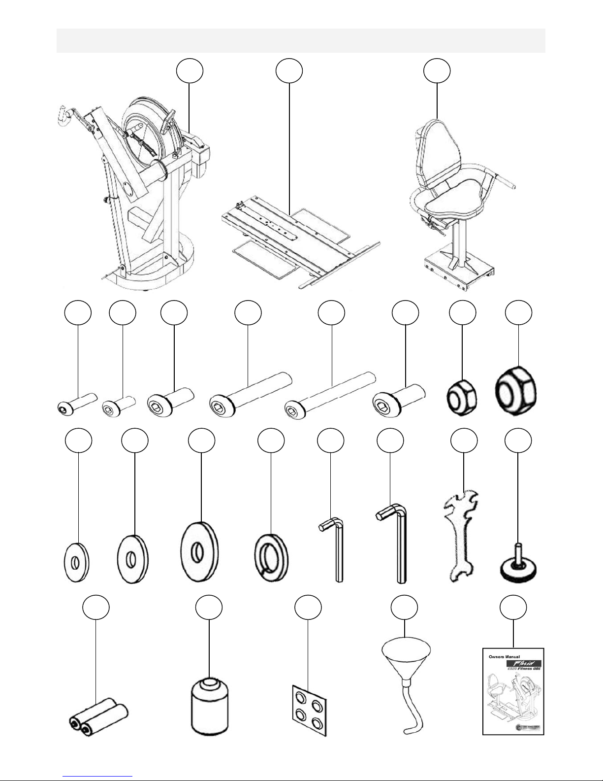
Box Contents
1
10
2
3
4
5
6
7
8
9
11
19
18
17
16
15
14
13
12
20
21
22
23
24

5
Item Qty Description Item Qty Description
1 1
Main Frame with Telescoping
Tube and Internal Gas Assist
Shock
13 4 M8 Washer
2 1 Baseplate (Install P-8) 14 3 M10 Washer
3 1 Seat (Install P-11) 15 4 M8 Springs Washer
4 8 M6x20mm bolt 16 1 4mm Allen Key
5 4 M8x15mm blot 17 1 6mm Allen Key
6 1 M8x25mm blot 18 1 Multi-tool
7 10 M8x45mm blot 19 9 Frame Levelers
8 1 M8x70mm blot 20 2 AA Batteries
12 8 M6 Washer 24 1 Owners Manual
9 4 M10x20mm bolt 21 1 Touch up paint
10 3 M8 Nylock Nut 22 4 Water Treatment Tablet
11 2 M10 Nylock Nut 23 1 Funnel and Hose

6
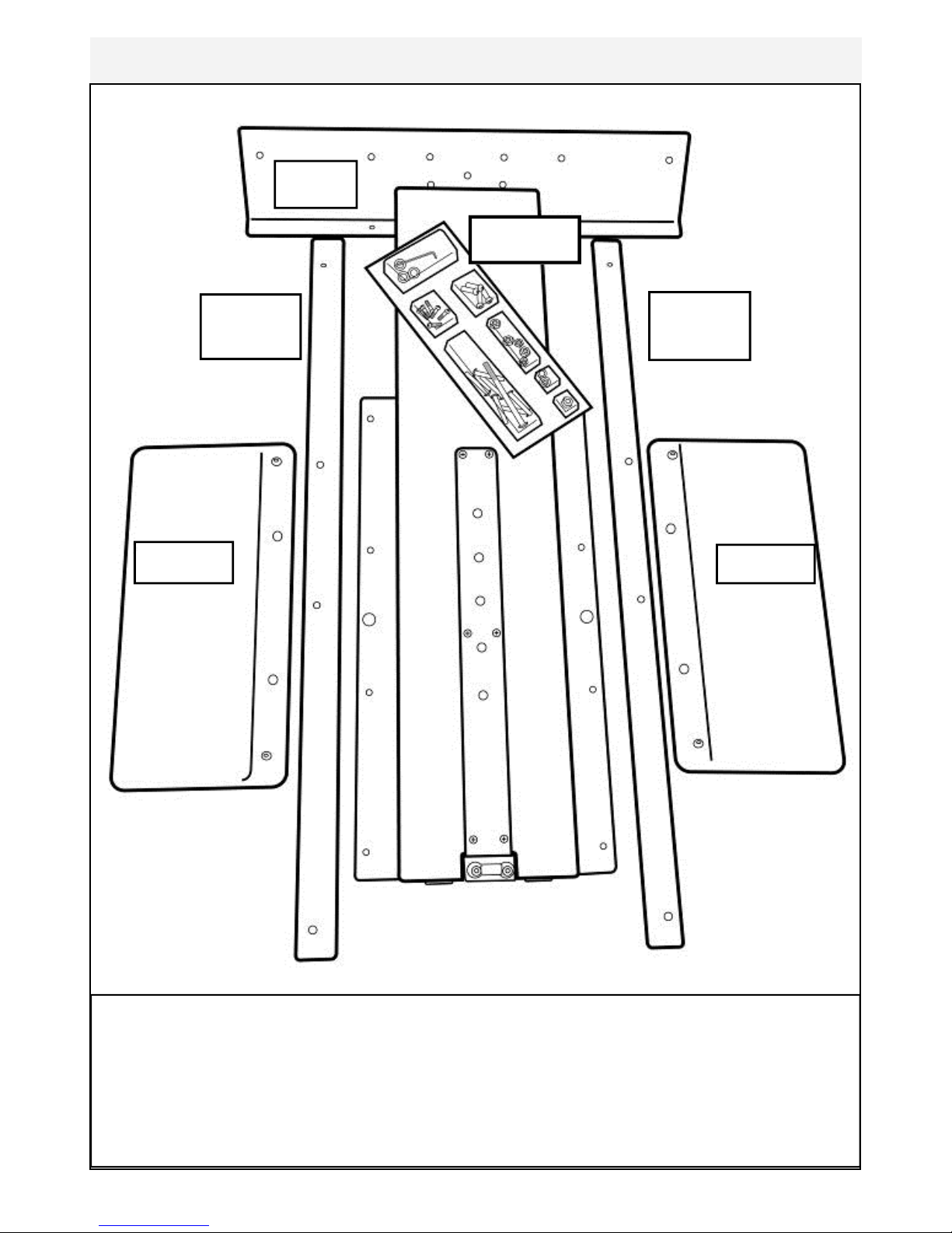
Assembly Instructions
4x 8x15mm bolts
and 4x M8 spring
washers
Adjuster knob
Remove contents from box. Attach telescoping tube to the underside of the control
arm using 4x M8x15mm bolts[5] and 4x M8 spring washers[15].
The control arm is heavy and may swing freely during this
stage of assembly. The Adjuster knob is pre-tightened from
the factory in the optimal position for assembly in relation to the control arm. Do not
loosen the Adjuster knob until the telescoping tube has been safely secured to the
underside of the control arm.
CAUTION

7
Secure right pedal onto Crank arm. The pedal threads have a blue coating which
will feel very tight when threaded onto the crank arm. This is a type of thread lock-
er, and once in contact with the crank arm threads will activate in approximately
15minutes.
Caution! Extreme over-tightening could damage the aluminum threads on the
crank arm.
Note: Allow 15 minutes for the thread
locker to activate before first time use.
Check pedal tightness periodically thereaf-
ter with a 15mm wrench.
8
Contents:
1x T-Track 2x Footplate
1x Channel Right 1x Bolt Pack (for both baseplate/seat)
1x Channel Left
T-Track
Footplate
Channel
Left
Footplate
Channel
Right
Bolt pack
Install the Baseplate

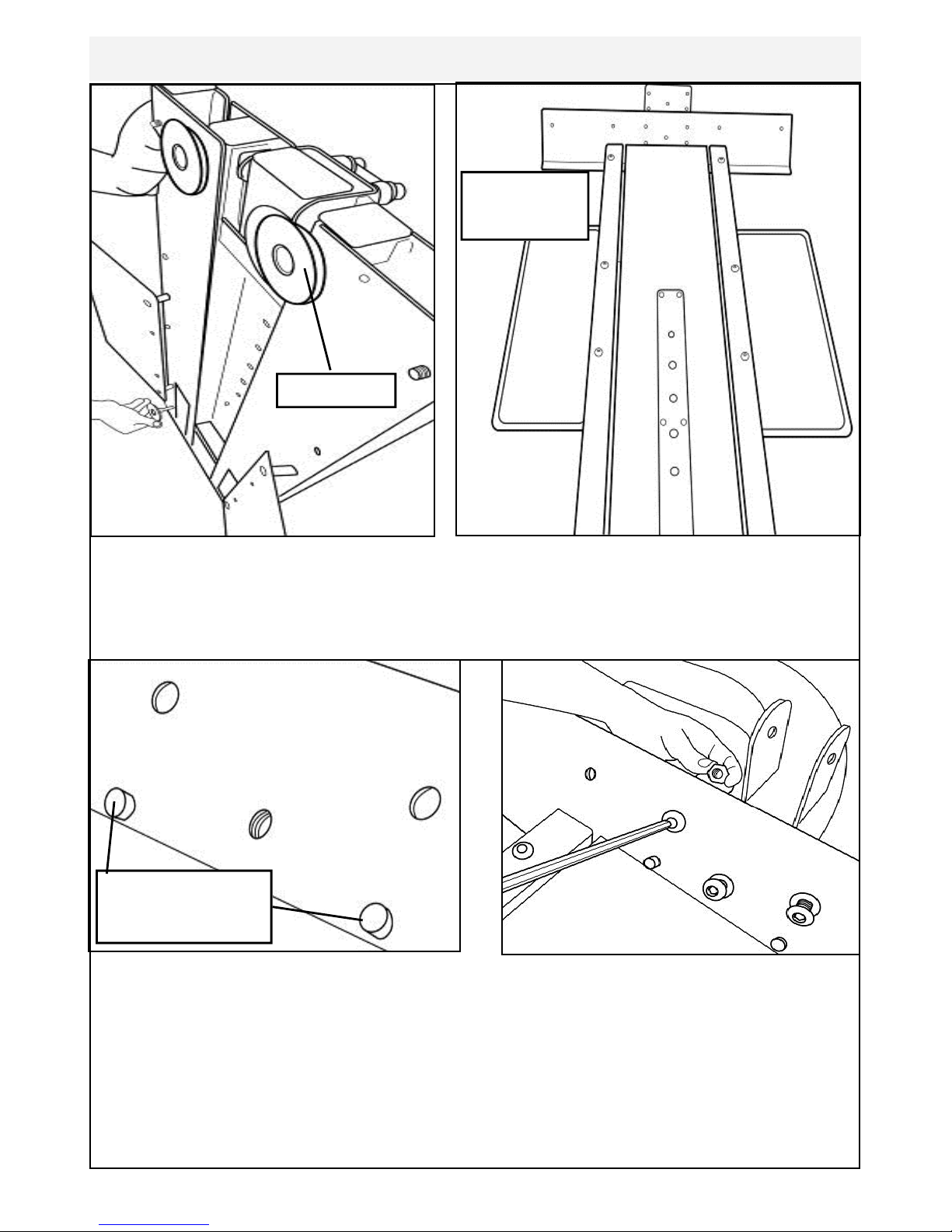
9
Slide Channel
forward
Left Channel
Footplate
T-Track
4x 8x45mm
bolts
Channel Slot
Tilt the T-Channel slightly to allow the footplate (with pre-installed bolts) to slide
underneath as shown.
Mount the Left Channel over the top of the footplate dome bolts and then slide for-
ward. Once Channel is properly positioned , attach to T-Track using 4x M8x45mm
Bolts[7].
Repeat this procedure to install Right Footplate and Channel.
10
Stand Baseplate upright to install 4x Foot levelers as shown.
Once foot levelers are installed, the completed baseplate can be
installed onto the mainframe of the E820.
Install Baseplate to Mainframe
Mount the baseplate onto the Mainframe using mounting pins as a locator
Then, secure with 3x M10x20mm Bolt[9], 2x M10 Nylock Nut[11] and 3x M10
Washer[14]
Note center M10 Bolt does not require Nut.
Foot leveler
Completed
Baseplate
Mounting pins on
E820 Mainframe

11
Seat back
Seat Assembly
CONTENTS:
1x Seat Main Frame 1x Lower Seat
1x Armrest Assembly 1x Upper Seat back
1x Bolt Pack (Note Bolts/Washers/Nuts are for both Seat and Footplate)
You will need the Lower Frame, Armrest Assembly and the following bolts/
washers/nuts from the bolt Pack:
1x M8x70mm Bolt 3x M8 Nylock Nut
1x M8x25mm Bolt 1x M8 Washer
2x M8x45mm Bolt
Bolt Pack
Seat
Armrest Assembly
Seat Main Frame

12
Mount the Armrest onto the Lower frame
from behind as shown.
Important! Before securing bolts (see
following page), thread the plastic tie at-
tached to the armrest cable through the
hole as shown right.
Secure Armrest with M8x70mm Bolt[8],
M8 Nylock Nut[10] and M8 Washer[13]
as shown
Plastic tie
Attaching Armrest to Lower frame

13
M8x25mm Bolt[6] and M8 Washer[13]
2x M8x45mm Bolt[7],2x M8 Nylock Nut
[10] and 2x M8 Washer[13]

14
Attaching Armrest cable to Cable Pivot
Now secure the cable end with the
M10x20mm bolt[9]. Before tightening
the bolt into position, the plastic tie end
can be discarded
Locate plastic tie, then depress Cable
Pivot forward to allow plastic tie to be
pulled through the hole in front. Once
the cable end is through the hole, slide it
forward as shown upper right to prevent
cable end from slipping back through.
Cable Pivot
Cable Pivot
Plastic tie
M10x25mm
bolt

15
Install Seat Back and Seat
Seat Frame, Seat Back and Seat, 8x
M6x20mm Bolt[4] and 8x M6 Washer
[12]
Install Seat Using 4x M6x20mm Bolt[4]/
Washer[12].
Install Seat Back with as shown with 4x
M6x20mm Bolt[4]/Washer[12]
Once seat pads are installed the assem-
bly will be complete. Check to be sure
that all bolts are securely tightened and
that the cable lever is functioning normal-
ly.
To mount the seat onto the completed
baseplate assembly, align the seat with
the rear of the T-track and depress cable
lever. Tip: Lift entire seat slightly and
slide onto T-track when level to avoid
binding.
Once seat is on T-track, engage the rear
seat stop for safety.
Seat back
Seat

16
Install Seat onto Baseplate
Seat Stop
Seat Stop: Must be lowered to allow
seat onto Baseplate track.
Must ALWAYS be in the LOCKED
position when seat is occupied on
Baseplate.
Must be lowered to allow seat removal.
To LOCK, raise and locate. To
Seat Installation: Tilt the seat slightly
upward to allow the front rollers to en-
gage the channel. Then, lift the rear lev-
el and, while engaging the Seat Lock Re-
lease Lever, slide the seat onto the
Baseplate as shown.
Usage: The seat has four positions. To
move forward or rearward, depress the
Seat Lock Release Lever and move
freely to whichever position you require.
CAUTION: The Seat Stop Must be in
the LOCKED position whenever the
seat is in use.
To remove the seat: Lift and lower the
Rear Safety lock, depress the Seat Lock
Release Lever and slide the seat rear-
ward.
WARNING: Do not under any circum-
stances attempt to remove/install seat
while occupied.

17
Control Arm
Chain tensioning bolts: Allows for tightening the chain or adjustment from side to
side. Make sure when tightening only to adjust the same amount for both bolts,
otherwise the sprocket will be misaligned.
Note: Tightening the right bolt only will pull the right side of the crank assembly to-
ward you, tightening the left will pull the left side toward you. Use this feature to re-
align the rear with the front sprocket if needed or when changing to a new chain.
Crank arm bolts: Loosen all 8
bolts slightly before adjusting/
tightening chain.
Inspection plate: Open to
check chain tension.
Warning:
Do not check chain tension
with fingers!
Adjuster Knob: Loosen to allow the con-
trol arm to travel through 90 degrees of
travel. Note the telescoping tube is gas
assisted.
Tighten securely when desired workout
position is reached.

18
Tank Filling and Water Treatment
Yellow Tank
Plug
Note: A large bucket is required for filling (Not included).
In areas where tap water quality is known to be poor, FDF recommends the use of
distilled water.
Open the tank plug and insert hose into tank (rotating the impeller slightly may be
necessary to allow the hose to pass), move the tank adjuster handle to level 20 and
begin filling. Do not fill the tank higher than the level indicator on the front of the
clear shell. A properly filled tank holds approximately 8 liters of water.
Warning
Do not under any circumstances
put fingers into the tank. Use the
end of the hose to move the impel-
ler should the need arise.
Note: Lower
tank plug is
permanently
sealed.
Use a drop cloth under the tank
when filling the tank to avoid dam-
age floor or carpet
Caution
Water Treatment Procedures:
Add Chlorine tablet.
Note: The amount of water treatment can vary widely depending on the Rower’s
location and exposure to sunlight. DO NOT, UNDER AN CIRCUMSTANCES USE
ANY TREATMENT TABLETS OTHER THAN THOSE SUPPLIED WITH YOUR
ROWER. Your rower box contents include 4x water treatment tablets, which is suf-
ficient for several years of water treatment. Treat when water becomes discolored
or shows signs of Algae/Bacterial growth. To purchase additional chlorine tabs,
please consult your nearest regional dealer/distributor or check our website
at www.firstdegreefitness.com

19
Long Term Water Treatment and Basic Operation
Long term water treatment:
Water treatment schedules for the E820 will vary according to the fluid
tanks exposure to sunlight but expect 8-12 months near a bright, sunlit
window and 2-4 years for a darker location. At the point of finding the
water slightly green, add a Chlorine tablet. .
Important: Do not fill past the calibration mark as indicated on the tank
level sticker or water spillage may occur. See tank filling and water treat-
ment page for details.
Removing hands before the crank
comes to a complete stop while
training can cause injury. The crank
is direct drive so as to allow both
forward and reverse rotation during
workouts.
Warning:
CAUTION
Resistance:The level of resistance
is determined by the level indicator
located on the front of the tank.
Level one indicates lightest re-
sistance, level twenty represents
heaviest resistance. Allow three to
four seconds after adjusting re-
sistance handle for the correct re-
sistance level to be achieved.

20
Rower Ergometer
Quick start: Provides instant workout information. Just start training to activate.
You can choose to change UNITS displayed
UNITS: Displays WATTS, SPM, HR, 500/m
LEVEL: Adjustable from 1-20. Match LEVEL number with resistance level on
the Fluid tank.
SET: Changes Time, Distance parameters
PROGRAM: Clears current exercise program
RESET: Clears data
Note: For complete operational instructions, please refer to the computer
manual, which is included with your E-820 Series rower.
Other manuals for E820 Fitness UBE
2
Table of contents
Popular Elliptical Trainer manuals by other brands

Horizon Fitness
Horizon Fitness Evolve 5 Assembly guide

LifeCore Fitness
LifeCore Fitness LC-990 Assembly instructions

Sunny Health & Fitness
Sunny Health & Fitness SF-B0419 user manual

NordicTrack
NordicTrack Elliptical E7.1 Manual Del Usuario

Vision Fitness
Vision Fitness X1400 Assembly guide

Sunny Health & Fitness
Sunny Health & Fitness SF-E3416 user manual


NordicTrack
NordicTrack E 7.9 Elliptical manual

NordicTrack
NordicTrack E4.0 Elliptical Manuel de l'utilisateur

Horizon Fitness
Horizon Fitness ENDURANCE Owner's & assembly guide

HMS
HMS M2218 Manual instruction

Klarfit
Klarfit 10006712 manual

Progear Fitness
Progear Fitness Air elliptical pro 1307 owner's manual