Fluigent ESS SWITCHBOARD User manual

User Manual
ESS™ platform: SWITCHBOARD, M-SWITCH™, -SWITCH™ and
2-SWITCH™
Version 10A

Page - 2
1.
INTRODUCTION 6
2.
FLUIDIC CIRCUITS EXA PLES 7
3.
USING A 2-SWITCH™ VALVE 8
3.1
Fluidic principle 8
3.2
Description 9
3.2.1
2-SWITCH™ Front 9
3.2.2
2-SWITCH™ Back 10
3.2.3
2-SWITCH™ Top and Bottom faces 11
3.3
Connection 12
3.3.1
Fluidic connection 12
3.3.2
Electric connection 15
3.4
Positioning 16
4.
USING AN -SWITCH™ VALVE 19
4.1
Fluidic principle 19
4.2
Description 20
4.2.1
M-SWITCH™ Front and top 20
4.2.2
M-SWITCH™ Back 21
4.2.3
M-SWITCH™ Bottom face 21
4.2.4
M-SWITCH™ Side face 21
4.3
Connection 22
4.3.1
Fluidic connection 22
4.3.2
Electric connection 25
4.4
Positioning 26
5.
USING AN L-SWITCH™ VALVE 28
5.1
Fluidic principle 28
5.2
Description 29
5.2.1
-SWITCH™ Front and top 29
5.2.2
-SWITCH™ Back 30
5.2.3
-SWITCH™ Bottom face 30
5.2.4
-SWITCH™ Side face 30
5.3
Connection 31
5.3.1
Fluidic connection 31
5.3.2
Electric connection 37
5.4
Positioning 38
6.
USING THE SWITCHBOARD 40
6.1
Description 40

Page - 3
6.2
Connection 41
7.
HOW TO USE THE 2-SWITCH™, -SWITCH™
AND L-SWITCH™ WITH GAS 43
8.
HOW TO START WORKING WITH THE ESS™ 46
9.
FREQUENTLY ASKED QUESTIONS 47
10.
SPECIFICATIONS 48

Page - 4
WARRANTY TER S :
What This Warranty Covers
This warranty is granted by Fluigent and applies in all countries.
Your Fluigent product is guaranteed for one year from the date of delivery at your laboratory against defects in
materials and workmanship.
If found to be defective within the warranty period, your Fluigent product will be repaired or replaced free of
charge.
What This Warranty Does Not Cover
This warranty does not cover routine maintenance, or damage resulting from the failure to maintain the product
in accordance with instructions provided by Fluigent. This warranty also does not cover damage that arises from
accidental or intentional misuse or abuse, alteration or customization, or repaired by unauthorized persons.
How to Get Service
If something goes wrong, contact the Fluigent dealer from whom you purchased your product. Arrange a
mutually convenient time for Fluigent service representative to discuss over the problem and find a solution to
fix the issue. Will be favored any remote repairs, but in case more actions need to be taken, the system will come
back to Fluigent offices (for no additional cost, only if it is under warranty).
The warranty conditions are:
Do never open the SWITCHBOARD, 2-SWITCH
™
, -SWITCH
™
and M-SWITCH
™
devices.
Do not use other cables than cables provided by Fluigent.
Prevent foreign objects or liquids from entering the SWITCHBOARD.
Prevent foreign objects from entering the 2-SWITCH
™
, -SWITCH
™
and M-SWITCH
™
devices.
Connect the power cord to an AC outlet of the correct voltage.
Use the right RJ45 port on the SWITCHBOARD with the right device.
Do not place the product in an unstable location, place the unit in a location with a level surface and a
strong and stable support.
If you are using the ESS™ platform with other flow control systems, please check that the pressure in
your fluidic system does not exceed 100 psi.
Respect the temperature compatibility (from 5°C to 50 °C).
Use the specific connectors provided by Fluigent (Teflon fittings and nuts for the 2-Switch
™
).
Only use 1/16’’ OD tubings with the valves (each type).
For specific use, please contact our Support team at [email protected]

Page - 5
WARNINGS:
Do never open SWITCHBOARD, 2-SWITCH™, -SWITCH™
and M-SWITCH™ devices. Refer all servicing to
after-sales service department (support@fluigent.com).
Prevent any objects or liquids from entering the SWITCHBOARD, this may cause a short-circuit failure
or other malfunction. Failing to respect this advice would:
-Expose you to direct current/voltage in case the device is under voltage which may lead to severe
damages
-Void device’s warranty
-Discharge our company from any liability regarding physical or device damages
Do not place the product in an unstable location, place the device in a location with a level surface and
a strong and stable support.
Do not use other power supply than the one provided with the ESS™. The power supply provided with
the ESS™ has been carefully selected to meet the power requirements of the ESS™ in all configurations
and to comply with all safety standards.
If you are using the ESS™ platform with other flow control systems, please check that the pressure in
your fluidic system does not exceed 100 psi

Page - 6
1. Introduction
The Easy Switch Solutions™ platform (or ESS™) provides solutions for path selection in microfluidics. The Easy
Switch Solutions™ platform enables you to implement three (3) different kinds of valves in your microfluidic
circuit.
The 2-SWITCH™ is a 3-port / 2-position solenoid valve: two (2) ports can alternatively be connected to
a third one. The 2-SWITCH™ is fully described in §3.
The -SWITCH™ is an 11-port / 10-position rotary valve: ten (10) peripheral ports can alternatively be
connected to a central one. The M-SWITCH™ is fully described in §4.
The L-SWITCH™
is a 6-port/ 2-position valve for injecting precise volume of fluid or for switching the
fluid to different channels. The -SWITCH™
is fully described in §5.
The fourth element of the Easy Switch Solutions™ platform is the SWITCHBOARD: this device hosts up
to four (4) M-SWITCH™ or -SWITCH™ and eight (8) 2-SWITCH™ and provides them power supply. The
SWITCHBOARD is also the link between the connected 2-SWITCH™, M-SWITCH™ and -SWITCH™ and
the controlling software ESS™ Control (cf. ESS™ Control User Manual). The SWITCHBOARD is fully
described in §6.
Combining the 2-SWITCH™, M-SWITCH™ and -SWITCH™ valves thanks to the SWITCHBOARD will give you new
possibilities to easily design and build even the most complex microfluidic circuits. It is also a powerful tool to
simplify your chip design and automate your experiments.
The ESS™ platform has been designed to work at its best performances with FLUIGENT flow control solutions
(MFCS™ and Flow-Rate Platform). It is however possible to use the ESS™ platform with other flow control systems
provided that the pressure applied to the ESS™ devices does not exceed 100 psi.
The ESS™ user manual will show you how to use the ESS™ elements for your daily work. It will describe all the
ESS™ functionalities that will help you to rationalize your microfluidic circuits and automate your experiments.
You will also find examples of applications using the ESS™ and answers to the frequently asked questions about
the ESS™. With these elements you will be able to exploit the full performances of the Easy Switch Solutions™
platform for your application.

Page - 7
2. Fluidic circuits examples
Page - 8
3. Using a 2-SWITCH™ valve
3.1 Fluidic principle
The 2-SWITCH™ is a 3-port / 2-position valve. This means that three (3) ports can be connected with fittings and
tubings to your application, and that it is possible to choose between two (2) positions linking the ports in two
(2) different manners.
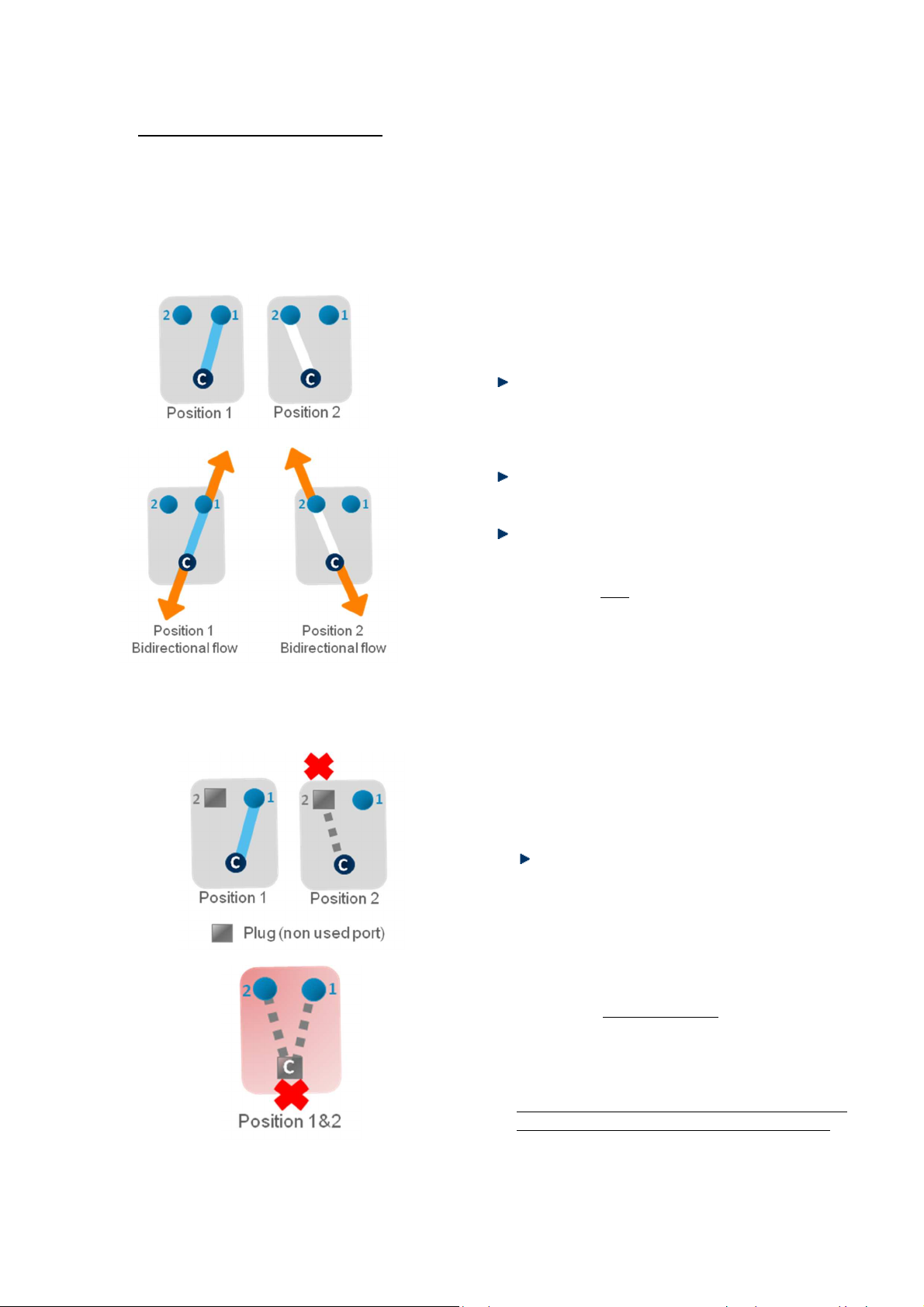
Fluidic 2-way switch
Here is the fluidic diagram of a 2-SWITCH™. The
dark blue “C” port at the bottom of the 2-SWITCH™
is the common port: it can be either connected to
port #1 or to port #2 depending on the chosen
position.
Position 1 connects the common port to port
#1 and Position 2 connects the common port
to port #2. The 2-SWITCH™ enables you to
switch between these two positions.
The Default position of the 2-SWITCH™ when
the 2-SWITCH™ is not powered is Position 1.
The 2-SWITCH™ is a bidirectional valve: the
fluid can flow in both directions inside the 2-
SWITCH™ i.e. from the common port to port
#1 / port #2 AND from port #1 / port #2 to the
common port.
Fluidic on/off switch
Another possibility for using the 2-SWITCH™ is to
connect a plug to either port #1 or port #2. This way,
one of the positions of the 2-SWITCH™ (Position 1 for
port #1 or Position 2 for port #2) becomes a closed
position, and the 2-SWITCH™ acts as a fluidic “on/off”
switch.
Example: A plug (gray square) is connected to
port #2. Position 2 is thus closed. In Position 1
fluids can flow through the valve between the
common port and port #1, whereas in Position 2
the fluidic path is closed between the common
port and port #2.
Warning: The fluidic “on/off” switch configuration
only works if port #1 or port #2 is connected with a
plug. If the common port is plugged then no flow
can circulate through the 2-SWITCH™ (bottom
diagram).
FAQ: Should I fill with liquid the plugged path inside
the 2-SWITCH™ before screwing the plug? (cf. §9)

Page - 9
3.2 Description
3.2.1 2-SWITCH™ Front
Here is a picture of the front of a 2-SWITCH™.
The 3 fluidic ports are at the bottom part of the device. The common port is the
central port, included in the device front. When looking at the front of the 2-
SWITCH™, port #1 is the right port and port #2 is the left one.
Two light indicators on the front show the current activated position of the 2-
SWITCH™:
A blue indicator (right) for Position 1 linking the common port to port #1 (right).
A white indicator (left) for Position 2 linking the common port to port #2 (left).
The front of the 2-SWITCH™ also includes a push button at the top to manually
switch between Position 1 and Position 2.
Port #2 Port #1
Common port Common port
Position 2
(white indicator)
Position 1
(blue indicator)
Position
switch
button

Page - 10
3.2.2 2-SWITCH™ Back
Here is a picture of the back of a 2-SWITCH™.
Port #1 is now at the left and port #2 is at the right.
At the centre of the back, a UNC ¼-20’’ thread is inserted to enable the user to
fasten the 2-SWITCH™ to the provided base or to any ¼-20’’ screw-mounted
device (as further explained in §3.4).
At the top of the device we can see the RJ45 port to connect electrically the 2-
SWITCH™ to the SWITCHBOARD. Two light indicators are associated with the
RJ45 port.
The orange indicator lights up when the 2-SWITCH™ is powered.
The green indicator lights up if a “Check connection” identification has
been requested for the 2-SWITCH™ from the SWITCHBOARD (cf. §6.2) or
from the ESS™ Control software (cf. ESS™ Control User Manual).
Warning: Please note that only straight-through wired RJ45 cables are
compatible with the ESS™ (to connect the 2-SWITCH™ with the
SWITCHBOARD). Other types of cable can damage the ESS™, and reciprocally,
the cables provided with the ESS™ should not be used for other applications.
F UIGENT advises to only use the cables provided with the ESS™ for ESS™
operation.
Orange indicator
(Power OK)
Orange indicator + green indicator
(Power OK + Check connection)
RJ45 Port
Port #1
Port #2
¼
-
20’’
insert

Page - 11
3.2.3 2-SWITCH™ Top and Bottom faces
Top face
Here is a picture of the top face of a 2-SWITCH™.
A UNC ¼-20’’ thread is inserted in the centre of
the top face so that the 2-SWITCH™ can be
fastened to the provided base or to any ¼-20’’
screw-mounted device (as further explained in
§3.4).
Bottom face
Here is a picture of the bottom face of a 2-
SWITCH™. A UNC ¼-20’’ thread is inserted in
the centre of the bottom face so that the 2-
SWITCH™ can be fastened to the provided base
or to any ¼-20’’ screw-mounted device (as
further explained in §3.4).
The bottom face and the top face of the 2-SWITCH™ are complementary: two 2-SWITCH™ can be assembled
together by inserting the top face of one 2-SWITCH™ in the bottom of another 2-SWITCH™. Please see §3.4 for
more details.
Page - 12
3.3 Connection
3.3.1 Fluidic connection
Description of the fittings and tubings
A 2-SWITCH™ has three (3) fluidic ports, described in §3.1 as “Common port”,
“Port #1” and “Port #2”.
The characteristics of those three (3) ports are:
Thread-size: 10-32.
Flat-bottom type (FB).
Compatible with tubings of 1/16’’ external diameter (1/16’’ OD).
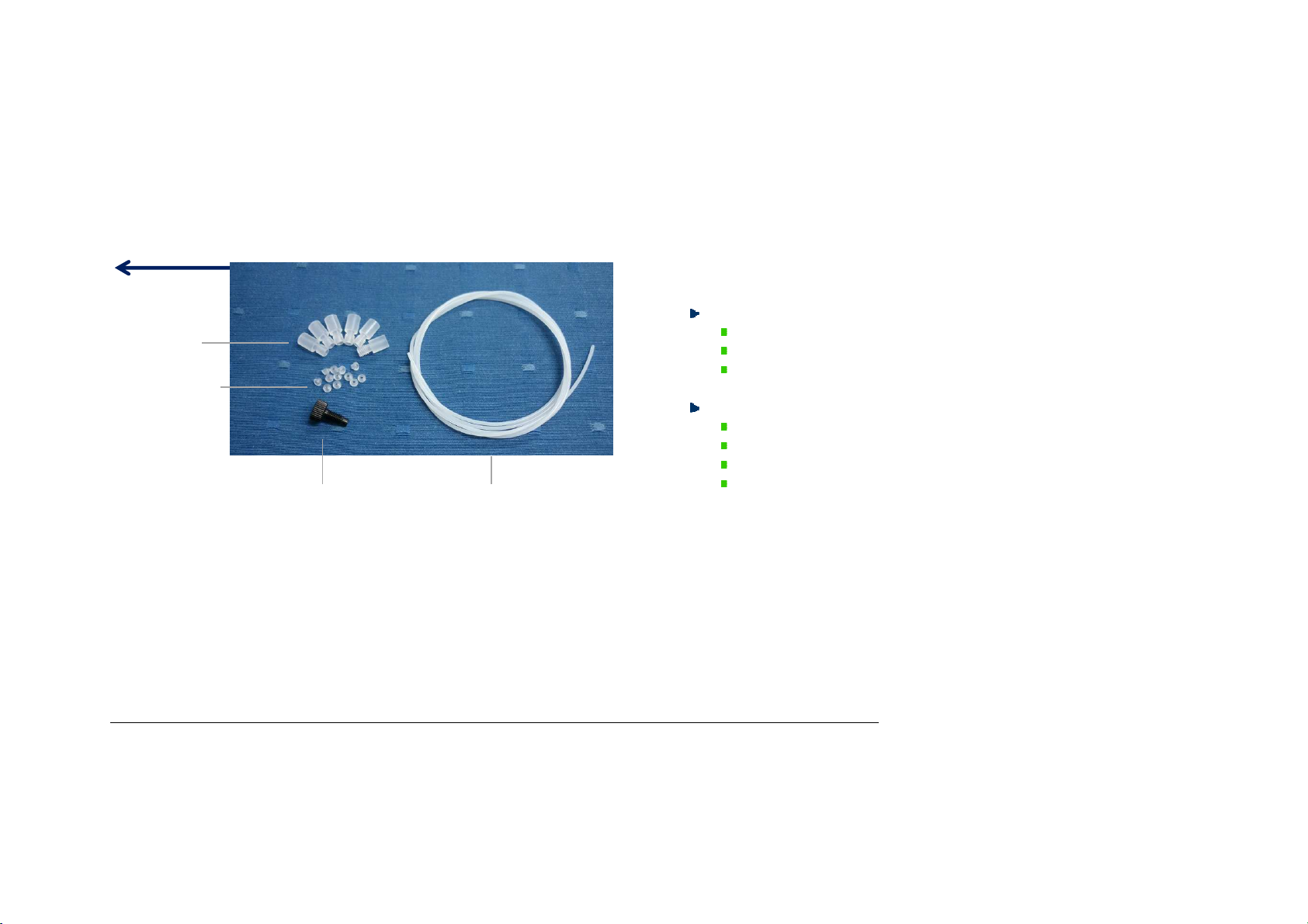
To get started, F UIGENT provides you, into the “KIT ESS 2-SWITCH “ :
Six (6) 2-SWITCH™ Teflon connectors.
Twelve (12) 2-SWITCH™ ferrules 1/16’’
One (1) plug Delrin® - 10-32 Flat Bottom.
One (1) meter of FEP tubing: 1/16’’OD (external diameter) and 0.010’’ID
(internal diameter). NB: There is a wide variety of materials and internal
diameters available with 1/16’’ tubing from fittings suppliers to suit your
application.
Warning: These fittings have been specifically selected by FLUIGENT to ensure good 2-SWITCH™ operation. F UIGENT advises you to use only these fittings on the 2-
SWITCH™.
Warning: Please note that only tubings of 1/16’’ external diameter should be used with the 2-SWITCH™. F UIGENT does not recommend the use of other tubings sizes with
or without tubing sleeves, as it can damage the 2-SWITCH™ and give non-tight fluidic connection.
NB: When the 2-SWITCH™ is not used or stored, F UIGENT advises you to connect plugs to all ports to protect the fluidic ports from dust.
FAQ: How can I make a junction between a 2-SWITCH™ and tubings with external diameters different from 1/16’’? (cf. §9)
2
-
SWITCH™
Teflon
connector
2-SWITCH™ ferrule 1/16’’
2
-
SWITCH™
plug Delrin®
10-32Flat Bottom
FEP Tubing 1/16’’OD x 0.010’’ ID
Page - 13
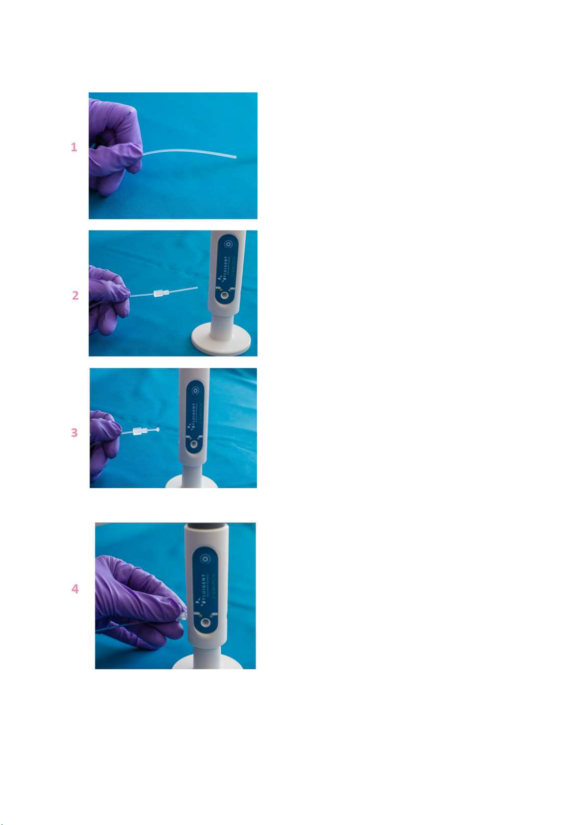
Connecting a 1/16’’ OD tubing to the 2-SWITCH™
1. Cut the 1/16’’ OD tubing to the desired
length, leaving a square-cut face.
2. Slide the nut over the tubing with the nut
thread facing the tubing end being
connected.
3. Slip the ferrule over the tubing, with the
tapered portion of the ferrule facing the
nut. NB: the nuts and ferrules are
specifically designed to work together.
F UIGENT advises you to only associate the
provided ferrules with the provided nuts
and vice-versa.
4. Insert the assembly into the receiving port,
and while holding the tubing firmly against
the bottom of the port, tighten the nut
finger tight.

Page - 14
5. To check the tightness of your connection,
you may pull gently on the tubing: it must
stay fitted in the ferrule and nut.
Connecting a plug to the 2-SWITCH™
1. Simply screw the plug in port #1 or port #2
finger-tight.
Fully connected 2-SWITCH™ in fluidic on/off
configuration. Position 1 is plugged and Position 2 is
opened.
.
Page - 15
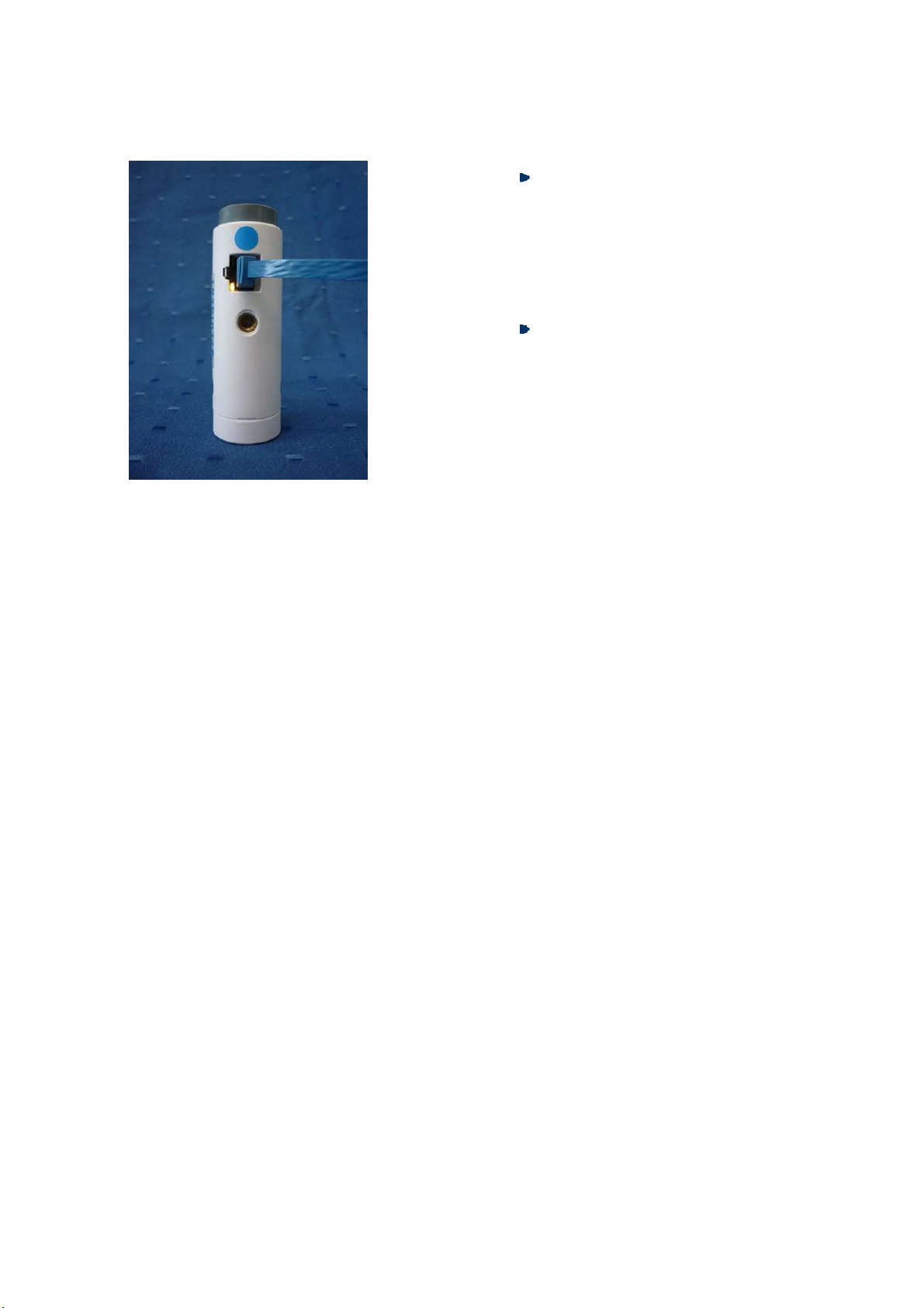
3.3.2 Electric connection
Simply plug one connector of the RJ45 blue
cable provided with the 2-SWITCH™ in the
female RJ45 plug at the back of the 2-
SWITCH™. The other connector should be
connected to a port in the blue cables
section of the SWITCHBOARD (See §6.2 for
more details)
If the 2-SWITCH™ is connected to a
powered SWITCHBOARD, the orange
indicator on the female RJ45 connector
lights up.
Warning: Please note that only straight-through wired RJ45 cables are compatible with the ESS™ (to connect
the 2-SWITCH™ with the SWITCHBOARD). Other types of cable can damage the ESS™, and reciprocally, the cables
provided with the ESS™ should not be used for other applications. F UIGENT advises to only use the cables
provided with the ESS™ for the ESS™.

Page - 16
3.4 Positioning
There are several possibilities to set the 2-SWITCH™ up. Please note that the 2-SWITCH™ device does not have
any imposed mounting orientation. The 2-SWITCH™ can be used in any spatial configuration.
Setting-up with the provided base
The base provided with the 2-SWITCH™ can be
screwed to any of its ¼-20’’ inserts.
Mainly, the 2-SWITCH™ can be set-up vertically
on the base by fastening the base into the ¼-20’’
insert of the bottom face or horizontally when
fastening the base into the ¼-20’’ insert of the
back.
NB: It is easier to first connect the RJ45 cable on
the 2-SWITCH™ before screwing the base on the
back face for horizontal positioning.
Vertical positioning
with base
Horizontal positioning
with base

Page - 17
Assembling several 2-SWITCH™ together using the complementary faces
The top and bottom faces of the 2-SWITCH™
devices are complementary: you can assemble
them together by inserting the top face of one
2-SWITCH™ into the bottom face of another 2-
SWITCH™.
As many 2-SWITCH™ as you need can be
assembled together horizontally, and
meanwhile can be set-up on their base fastened
into their back insert.
2-SWITCH™ devices can also be assembled
vertically. F UIGENT advises not to assemble
more than two 2-SWITCH™ together vertically.

Page - 18
Other possible setting-up
The three ¼-20’’ inserts of the 2-SWITCH™
can be used to mount the 2-SWITCH™ on
any frame or support equipped with ¼-20’’
pins such as a flexible rod as shown here
(not provided with the 2-SWITCH™).
¼-20’’ thread is also the standard for all
photographic equipment. You can use for
example a tripod for cameras and screw a
2-SWITCH™ on it (not provided with the 2-
SWITCH™).

Page - 19
4. Using an -SWITCH™ valve
4.1 Fluidic principle
The M-SWITCH™ is an 11-port / 10-position valve. This means that eleven (11) ports can be connected with
tubings, and that it is possible to choose between ten (10) positions linking one of the ten (10) external ports to
the central port of the valve.
Here is the fluidic diagram of an M-SWITCH™. The
dark blue port at the centre of the M-SWITCH™ is
the central port. The light blue ports are the
external ports. The central port can be connected
in turns to each external port, from port #1 to port
#10 depending on the chosen position
(respectively from Position 1 to Position 10).
The Default position of the -SWITCH™ when
the M-SWITCH™ is not powered is the last
actuated position.
The M-SWITCH™ is a bidirectional valve,
meaning that the fluid can flow inside the M-
SWITCH™ in both directions:
Distributor mode: fluid flows from the
central port to one external port
(according to the selected position).
Selector mode: fluid flows from one of
the external ports (according to the
selected position) to the central port.
The non used ports must be closed with
plugs (gray squares on the diagram) to
preserve the M-SWITCH™ good operation.
In the same way as the 2-SWITCH™, it is
possible to use a plugged position to close
a fluidic path.

Page - 20
4.2 Description
4.2.1 -SWITCH™ Front and top
Here is a picture of the front of an M-SWITCH™.
At the top of the picture, the fluidic head of the device can be seen. The head
holds the fluidic ports.
The head of the M-SWITCH™ is made up of the Ram which holds the integrated
fittings and the Spanner, which is tightened around the Ram to clench the
integrated fittings and make tight fluidic connections. The method to connect
tubings to the M-SWITCH™ is detailed in §4.3.1.
This manual suits for next models
3
Table of contents
Other Fluigent Laboratory Equipment manuals


