Siqura XCU Fusion User manual
XCU Fusion
316L stainless-steel dual imager camera
Installation Manual

Note: To ensure proper operation, please read this manual thoroughly before using the
product and retain the information for future reference.
Copyright © 2018 Siqura B.V.
All rights reserved.
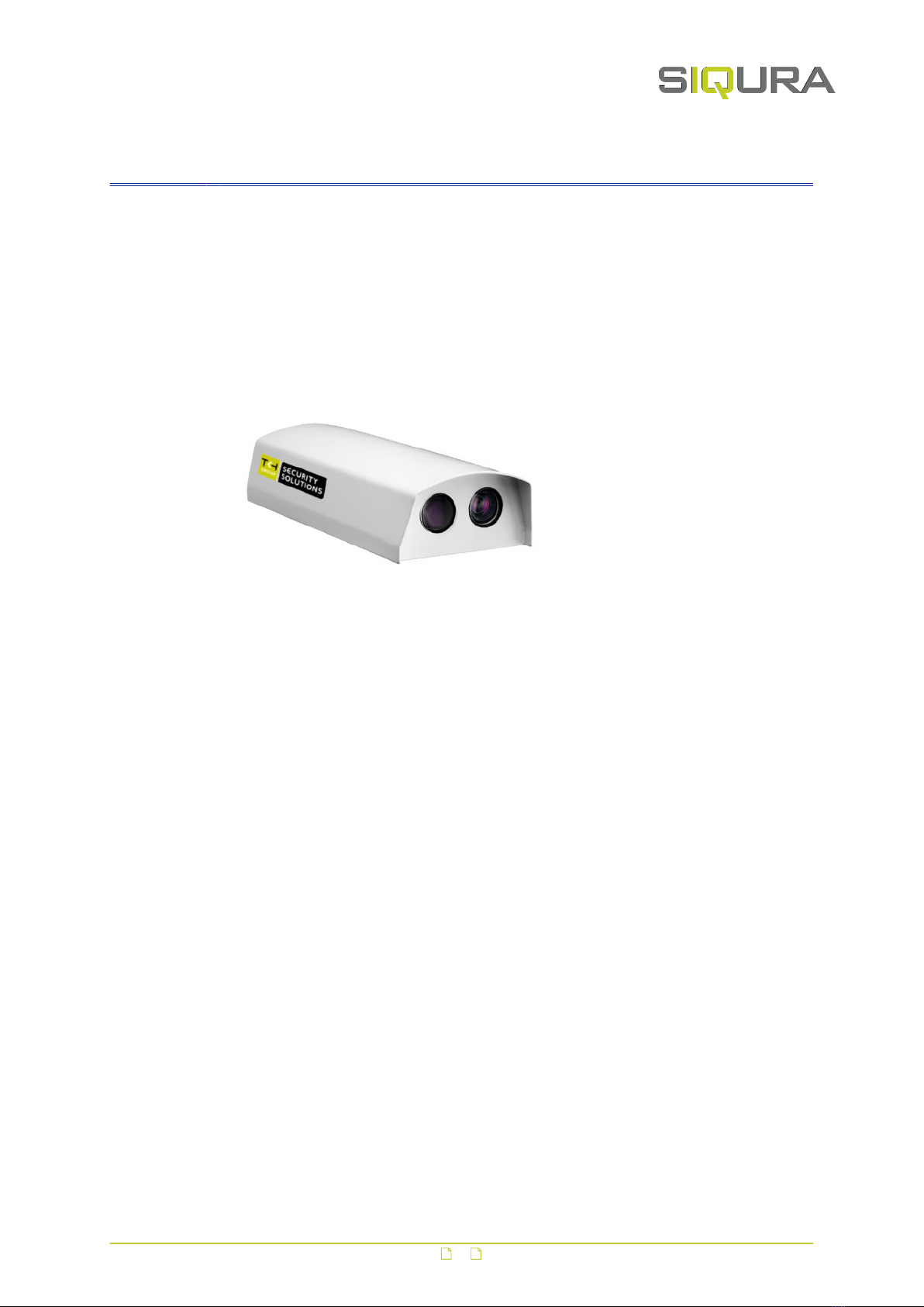
XCU Fusion
Installation Manual v3 (181804-3)
AIT55
Nothing from this publication may be copied, translated, reproduced, and/or published by
means of printing, photocopying, or by any other means without the prior written permission
of Siqura.
Siqura reserves the right to modify specifications stated in this manual.
Brand names
Any company, brand or product names mentioned in this manual are registered trademarks of
their respective owners.
Liability
Siqura accepts no liability for claims from third parties arising from improper use other than
that stated in this manual.
Although considerable care has been taken to ensure a correct and suitably comprehensive
description of all relevant product components, this manual may nonetheless contain errors
and inaccuracies. We invite you to offer your suggestions and comments by email via
[email protected]. Your feedback will help us to further improve our documentation.
How to contact us
If you have any comments or queries concerning any aspect related to the product, do not
hesitate to contact:
Siqura B.V.
Zuidelijk Halfrond 4
2801 DD Gouda
The Netherlands
General : +31 182 592 333
Fax : +31 182 592 123
E-mail : [email protected]
WWW : siqura.com
2

Contents
1 About this manual ..................................................................................... 4
1.1 Copyright and trademarks .................................................................... 4
1.2 Typographical conventions .................................................................... 5
1.3 Compliance information ........................................................................ 5
2 Identification ............................................................................................ 6
2.1 Models ............................................................................................... 6
2.2 Product markings ................................................................................. 7
3 Preparations ............................................................................................. 8
3.1 Unpack ............................................................................................... 8
3.2 Check package contents ....................................................................... 8
3.3 Discard packaging materials .................................................................. 8
4 Cables and connectors .............................................................................. 9
4.1 Recommended cables ........................................................................... 9
4.2 Connectors ......................................................................................... 9
4.2.1 Power ............................................................................................ 9
4.2.2 Ethernet ......................................................................................... 10
5 Mount and connect .................................................................................... 12
5.1 Wall/pole mounting .............................................................................. 12
5.1.1 Wall/pole mount accessories ............................................................. 12
5.1.2 Mount the bracket ............................................................................ 13
5.1.3 Attach safety cable .......................................................................... 14
5.1.4 Mount the camera ............................................................................ 14
5.1.5 Connect to network .......................................................................... 15
5.1.6 Connect to power ............................................................................ 15
5.1.7 Fix the camera position .................................................................... 15
5.1.8 Check installation ............................................................................ 16
5.2 Ceiling mounting ................................................................................. 16
5.2.1 Ceiling mount accessories ................................................................. 16
5.2.2 Mount the ceiling mount ................................................................... 17
5.2.3 Mount the camera ............................................................................ 17
5.2.4 Connect to network and power .......................................................... 19
5.2.5 Check installation ............................................................................ 19
6 Maintenance .............................................................................................. 20
7 Dimensions ............................................................................................... 21
7.1 Wall/Pole mount .................................................................................. 21
7.2 Ceiling mount ...................................................................................... 22
3

1 About this manual
What's in this manual
This manual gives you the information you need to install the XCU Fusion camera. It tells:
● How to mount the camera
● How to connect the camera
● How to power the camera
Who this manual is for
These instructions are for all professionals who will install the XCU Fusion.
Where to find more information
Find product specific datasheets, manuals, EU Declarations of Conformity and firmware
updates at siqura.com/downloads/software. Make sure that you have the latest version of this
manual.
What you need to know
You will have a better understanding of how this product works if you are familiar with:
● Camera technologies
● CCTV systems and components
● Ethernet network technologies and Internet Protocol (IP)
● Windows environments
● Video, audio, data, and contact closure transmissions
● Video compression methods
Before you continue
Read, fully understand and observe all instructions and warnings in this manual. Keep this
manual in a safe place for future reference. When you unpack this product, make sure there
are no missing or damaged items. If any item is missing, or if you find damage, do not install
or operate this product. Ask your supplier for assistance.
Why specifications may change
We are committed to delivering high-quality products and services. The information given in
this manual was current when published. As we continuously seek to improve our products
and user experience, all features and specifications are subject to change without notice.
Acknowledgement
This product uses the open-source Free Type font-rendering library. The Open Source
Libraries and Licenses document, available at siqura.com/downloads/software, gives a
complete overview of open source libraries used by our video encoders and IP cameras.
1.1 Copyright and trademarks
Any company, brand or product names mentioned in this manual are registered trademarks of
their respective owners.
4
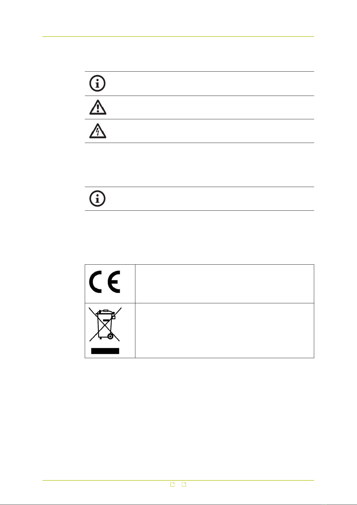
1.2 Typographical conventions
INFO
Read this information carefully to have a better understanding of the current or
following instructions.
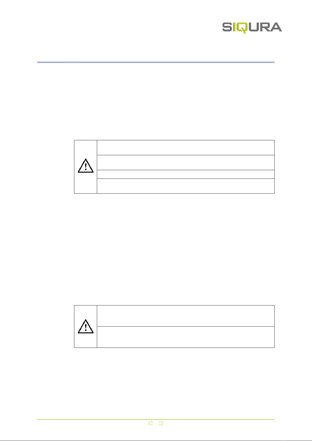
CAUTION!
Follow these precautions to prevent potential injury or material damage.
DANGER!
Follow these safeguards to prevent serious injury or death.
1.3 Compliance information
The XCU Fusion is in conformity with the certifications listed below.
Certifications:
● IP67
● CE
● FCC
EU Conformity Statement
This product and - if applicable - the supplied accessories too are
marked with "CE" and comply therefore with the applicable harmonised
European standards listed under the Low Voltage Directive
2014/35/EC, the EMC Directive 2014/30/EC, the RoHS Directive
2011/65/EU.
2012/19/EU (WEEE directive): Products marked with this symbol
cannot be disposed of as unsorted municipal waste in the European
Union. For proper recycling, return this product to your local supplier
upon the purchase of equivalent new equipment, or dispose of it at
designated collection points. For more information see:
www.recyclethis.info.
About this manual
5
2 Identification
In This Chapter
2.1 Models.................................................................................................................. 6
2.2 Product markings....................................................................................................7
2.1 Models
This section gives an overview of the powering, connectivity and mounting options for the
XCU Fusion series. More detailed information is given in the XCU Fusion datasheet.
Modular concept
The XCU Fusion comes in many variations, all sharing the same housing. For mounting and
connectivity purposes, a modular concept is introduced:
● XCU Fusion: This is the camera with the housing, excluding the bracket, mount or cable
connectors.
● Wall/Pole mounting bracket: This is the part with which the camera (via the swivel) will be
mounted, either on a wall or on a pole. The swivel on the bracket is used to fix the pan
and tilt position of the camera.
● Ceiling mount: This is the part with which the XCU Fusion can be ceiling or wall/pole
mounted.
● Connectors and cables.
Powering
Camera power can be supplied by:
● Line voltage (100-240 Vac)
● 24 Vdc / 24 Vac / PoE+
Connectivity
Models are available to connect the camera to:
● Ethernet (RJ-45)
● directly to fiber (dual LC SM)
● directly to existing coax (Ethernet over coax)
6

2.2 Product markings
The back of the camera housing has a label complying with CE
markings.
The label shows:
● Camera model name
● Article number (including bar code)
● Power supply (Volt)
● Frequency (Hertz)
● Current consumption (Amps)
● Compliancy (RoHS and Part 15 of FCC rules)
● Work order number (WO)
● Production year and month
● MAC address
● IP address
● Serial number
The side of the camera housing has the manufacturer's brand label.
The label shows:
● Camera brand
Identification
7
3 Preparations
In This Chapter
3.1 Unpack..................................................................................................................8
3.2 Check package contents.......................................................................................... 8
3.3 Discard packaging materials.....................................................................................8
3.1 Unpack
● On delivery of the product, make sure that the packaging shows no signs of
damage.
● If the packaging is visibly damaged, do not install or operate the unit. Report
any damage to the supplier immediately.
● Unpack and handle the unit carefully so as not to damage the product.
● For better grip and protection, you are advised to wear slip-resistant safety
gloves when handling the unit.
3.2 Check package contents
The package contents include the items below. Notify your supplier if any item is missing.
Camera
● XCU Fusion unit
Documentation
● 1x Quick Start Guide
3.3 Discard packaging materials
● You are advised to retain the original product packaging. Shipping the product
for repairs without the original packaging may cause product damage during
transport.
● The packaging materials can be recycled. If you discard the packaging,
properly separate the materials and dispose of them at your local waste
collection or recycling centre. Observe the local waste disposal regulations.
8
4 Cables and connectors
This chapter gives the requirements for cables and connectors used to connect the camera to
power and network.
In This Chapter
4.1 Recommended cables..............................................................................................9
4.2 Connectors............................................................................................................ 9
4.1 Recommended cables
Depending on the power supply, we recommend use of the following cables:
● 230/115 Vac:
-3 G, size 1.5 mm2
● 24 Vac/Vdc:
-up to 30 m, size 1.5 mm2
-up to 15 m, size 0.75 mm2
● Ethernet:
- Shielded AT5E S/FTP
● Power over Ethernet (PoE):
- 100 m, wire size AWG24 or less.
4.2 Connectors
4.2.1 Power
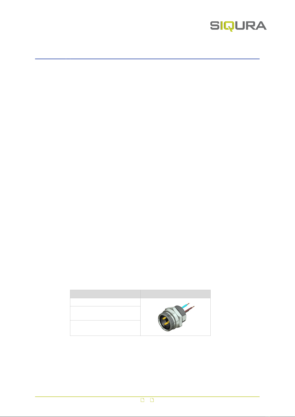
Power IP67 connector, size 7/8"
The standard power connector for 100-240 Vac, 24 Vdc or 24 Vac, located on the bottom
plate of the camera, is the CON CONEC RECEPT. PWR 3P IP67 0.5M AWG18.
CON CONEC RECEPT. Front view
IP67 rated (potted)
Temperature range -30 °C to
+75 °C
UL approved E331608
Accessories for power IP67 connector, size 7/8"
The CON CONEC PLUG PWR 3P IP67 AWG16 and CON IP67 CAP FOR 7/8" MALE accessories
are available for the standard power connector above.
9
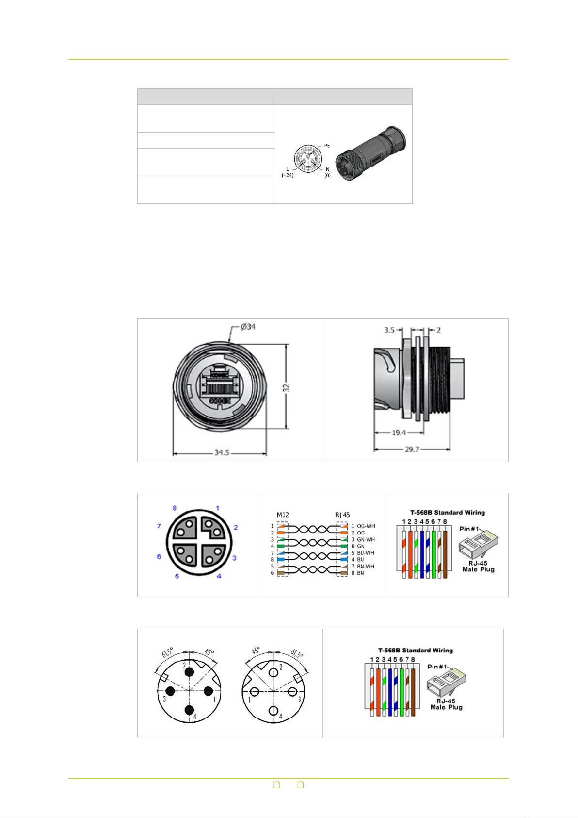
CON CONEC PLUG Front view
IP67 rated only when covered or
mated
Cable range 6-12 mm
Screw termination, Wire range
0.5 – 1.5 mm2
Temperature range -40 °C to
+85 °C
4.2.2 Ethernet
The standard Ethernet connector, located on the bottom plate of the camera, is the RJ-45
connector.
RJ-45 connector
Optional M12 X-coded Ethernet
Optional M12 D-coded Industrial Ethernet
Cables and connectors
10
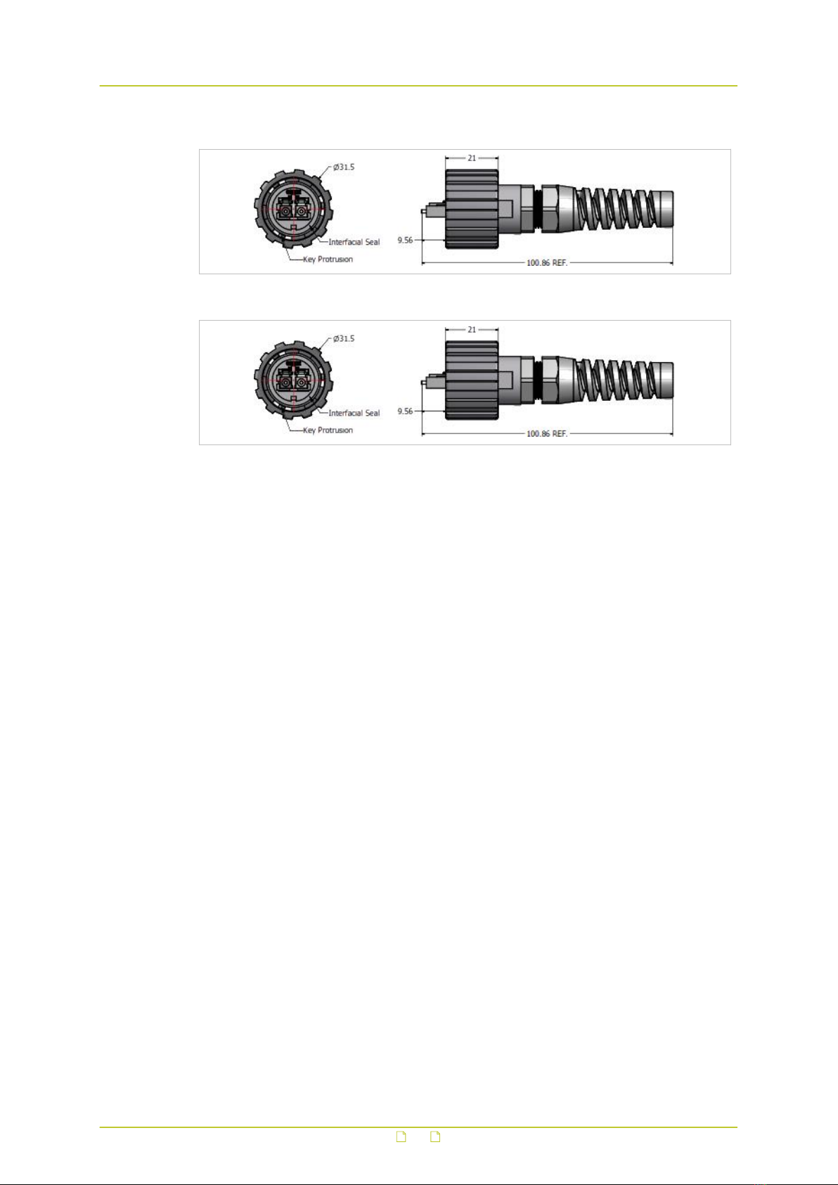
Optional fibre (2SM)
Optional fibre (2MM)
Cable part of the connector
The contra parts of the above connectors are available from Siqura as accessories.
Cables and connectors
11
5 Mount and connect
● Installation should be done by a qualified engineer and should conform to the
local code of practice and all relevant local and international standards.
● Disconnect the power from the camera during installation.
● It is recommended to fix the camera or its mounting brackets with anchors
or screws that can hold 100 kg or more per anchor or screw.
● Avoid strong light sources, such as the sun, shining straight into the lens.
● Use tools that are appropriate for the intended purpose.
● Check the supply voltage (marked on the label). An incorrect power supply
voltage may damage the unit.
● Do not open the camera to maintain the certification requirements and the IP
rating of the unit.
● Use the safety cable (supplied with the mount) to prevent the camera from
falling when mounting it on the wall/pole or ceiling mount.
In This Chapter
5.1 Wall/pole mounting............................................................................................... 12
5.2 Ceiling mounting...................................................................................................16
5.1 Wall/pole mounting
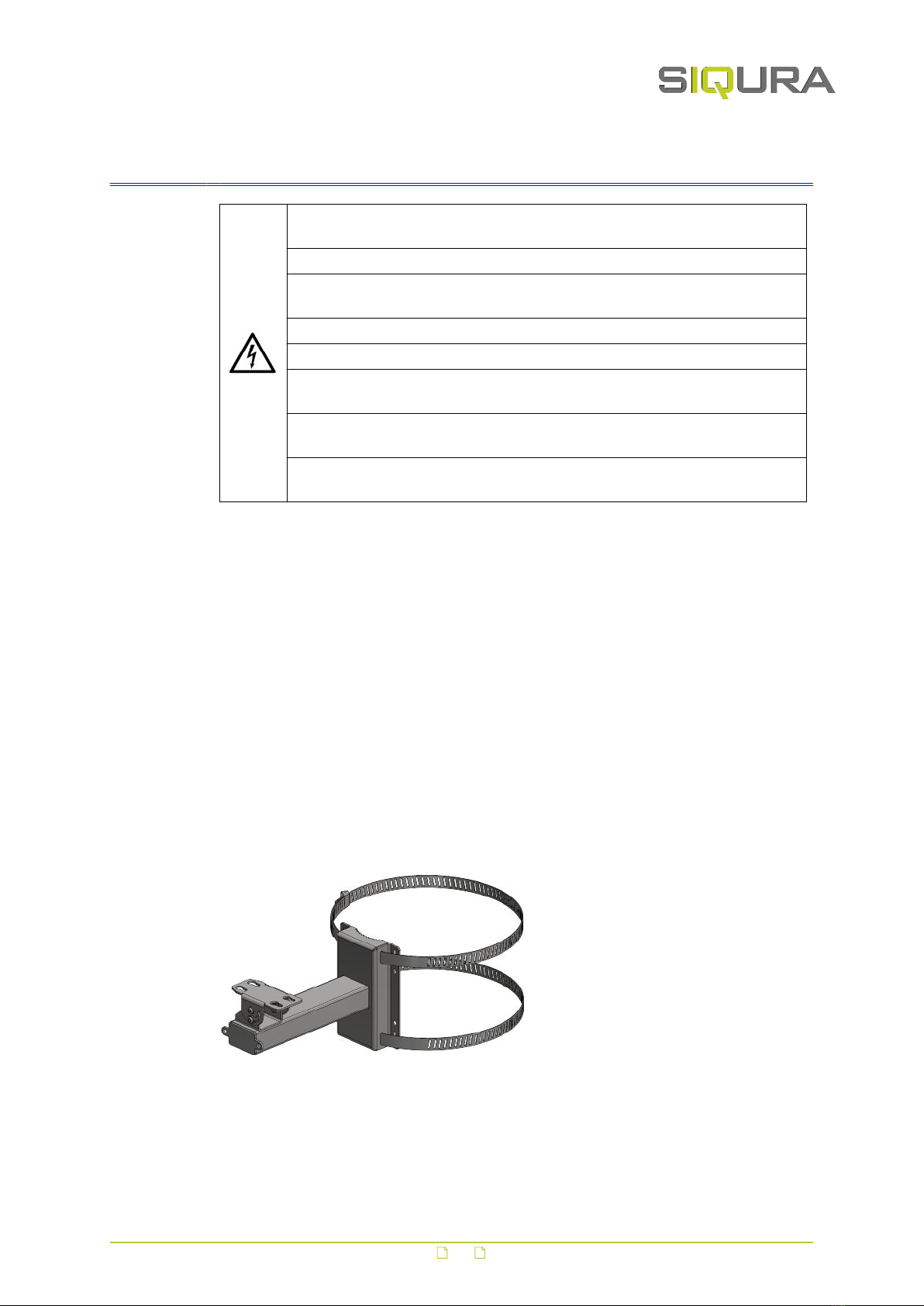
5.1.1 Wall/pole mount accessories
The following accessories can be supplied for wall mounting:
● XCUWM01: Wall/Pole mount
● XCUSS01: Sunshield
● XCUFP01: Safety cable
XCUWM01 Wall/Pole mount with pre-assembled swivel and straps
12

XCUSS01 Sunshield
SCUFP01 Safety cable (standard supplied with mounts)
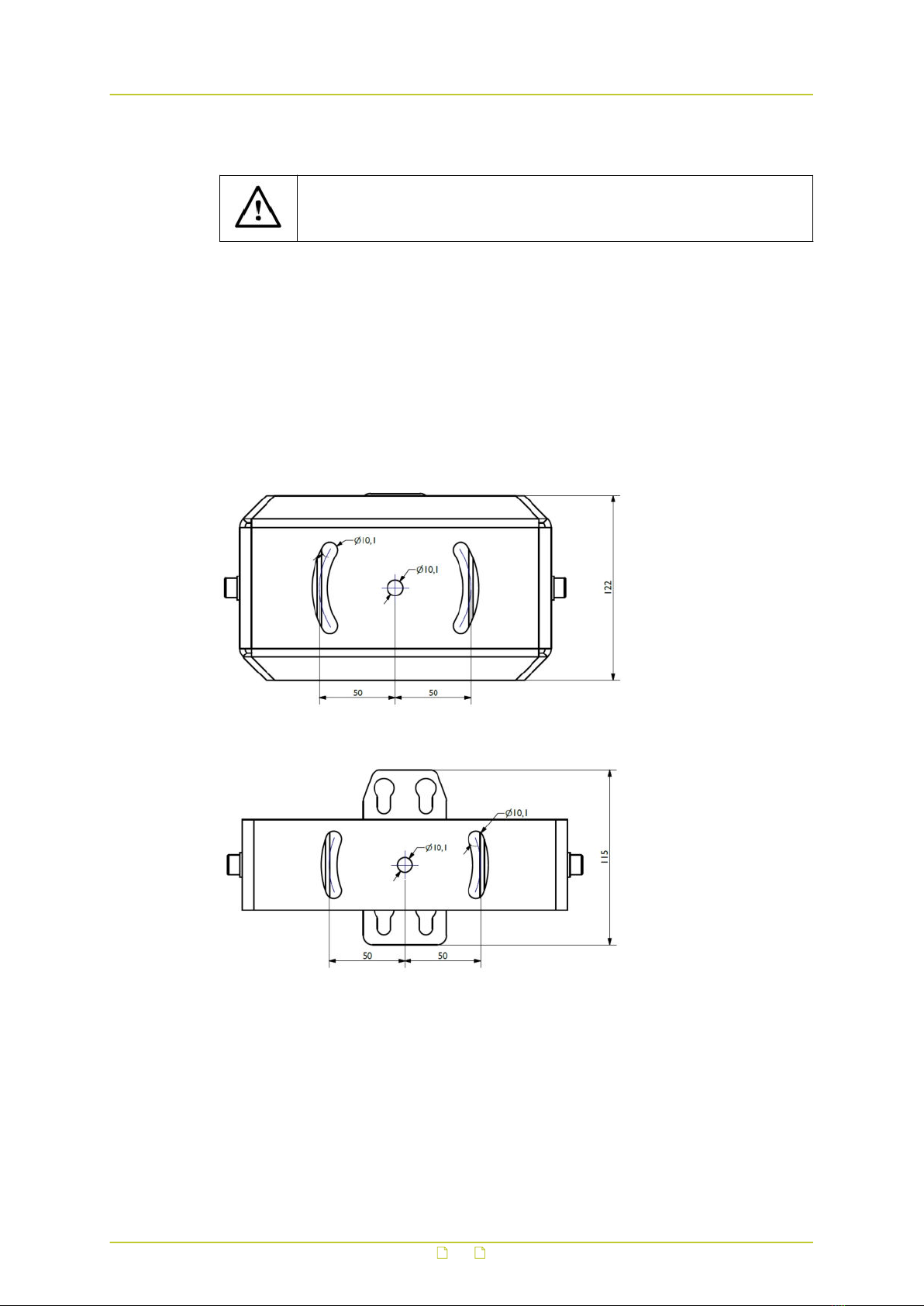
5.1.2 Mount the bracket
● When mounting the wall bracket, use anchors and screws (M8) which are
appropriate for the mounting surface.
● Each anchor or screw must be able to hold 100 kg.
Attach the bracket to the wall
1 Mark the drill hole positions (see the drilling template below).
2 Attach the bracket to the wall.
3 Rotate the swivel to be transverse to the bracket.
Drilling template
Attach the bracket to the pole
1 Mount the bracket to the pole using straps as indicated below.
Mount and connect
13

Bracket mounted to pole with straps
5.1.3 Attach safety cable
To prevent the camera from falling when installing, make sure to attach the supplied safety
cable:
1 Connect the safety steel cable to the attachment eye on the bottom of the camera.
2 Connect the other end of the cable to the attachment eye on the wall bracket.
5.1.4 Mount the camera
Mount the sunshield (optional)
1 Position the sunshield over the camera.
2 Align the nuts and bolts with the receiving holes on the sunshield.
3 Tighten the four locking nuts which fasten the camera to the sunshield.
Attach the camera to the swivel
1 Position the camera bottom over the swivel.
2 Align the nuts and bolts with the receiving holes on the swivel. See the bottom view
under Attach the camera to the ceiling mount (see "Mount the camera" on page 17).
3 Lower the camera onto the swivel.
4 Slide the camera into locking position on the swivel.
5 Tighten the four locking nuts which fasten the camera to the bracket.
Wall mounted XCU Fusion
Mount and connect
14
5.1.5 Connect to network
Connect the network cable
1 Open up the network connector cap.
Note: Leave the cap attached to its strap for re-use if you should need to disconnect
the network cable at a later stage. Use a tie wrap to secure the cap against wind, if
need be.
2 Insert the RJ-45 plug into the camera network connector.
3 Push the black ring towards the connector.
4 Turn the ring counter-clockwise to fasten the cable.
5.1.6 Connect to power
Depending on the model, the device can be provided with different power supply voltages.
Their value is shown on the product identification label (see "Product markings" on page 7).
● Make sure that the specifications for the power supply for the installation
correspond with those required by the device.
● Make sure that the power source and connecting cables are suitable for the
power consumption of the system.
Powering
Camera power can be supplied by:
● Line voltage (100-240 Vac)
● 24 Vdc / 24 Vac
● PoE+
Power the camera (100-240 Vac / 24 Vdc / 24 Vac)
1 Carefully align the cable connector holes correctly with the pins on the camera power
connector.
2 Push the cable connector into place.
3 Carefully turn the ring counter-clockwise to fasten the cable to the camera.
Make sure the ring is properly turned all the way up.
5.1.7 Fix the camera position
Horizontal and vertical camera position are fixed through the swivel.
Fix horizontal position
1 Rotate the camera to achieve the designated horizontal field of view.
2 Keeping the camera body in position, tighten the bolt which secures the swivel to the
bracket.
Mount and connect
15

3 To get access to the nut inside the swivel, you may need to tilt the camera.
4 Tighten the nut which holds the swivel.
Fix vertical position
1 Tilt the camera to achieve the designated vertical field of view.
2 Keeping the camera body in position, tighten the bolts (4x) which fix the tilt angle.
3 Do the same for the locking nuts (4x) inside the swivel).
5.1.8 Check installation
Inspect the mounting of the unit
1 Check if the unit and its bracket are properly secured by the mounting bolts and screws.
2 Check if the swivel is properly fixed to prevent the camera from rotating or tilting.
5.2 Ceiling mounting
5.2.1 Ceiling mount accessories
The following accessories can be supplied for ceiling mounting:
● XCUCM01: Heavy duty ceiling mount for XCU Fusion
● XCUCM02: Ceiling mount for XCU Fusion
● XCUSS01: Sunshield (only for use with ceiling mount XCUCM02)
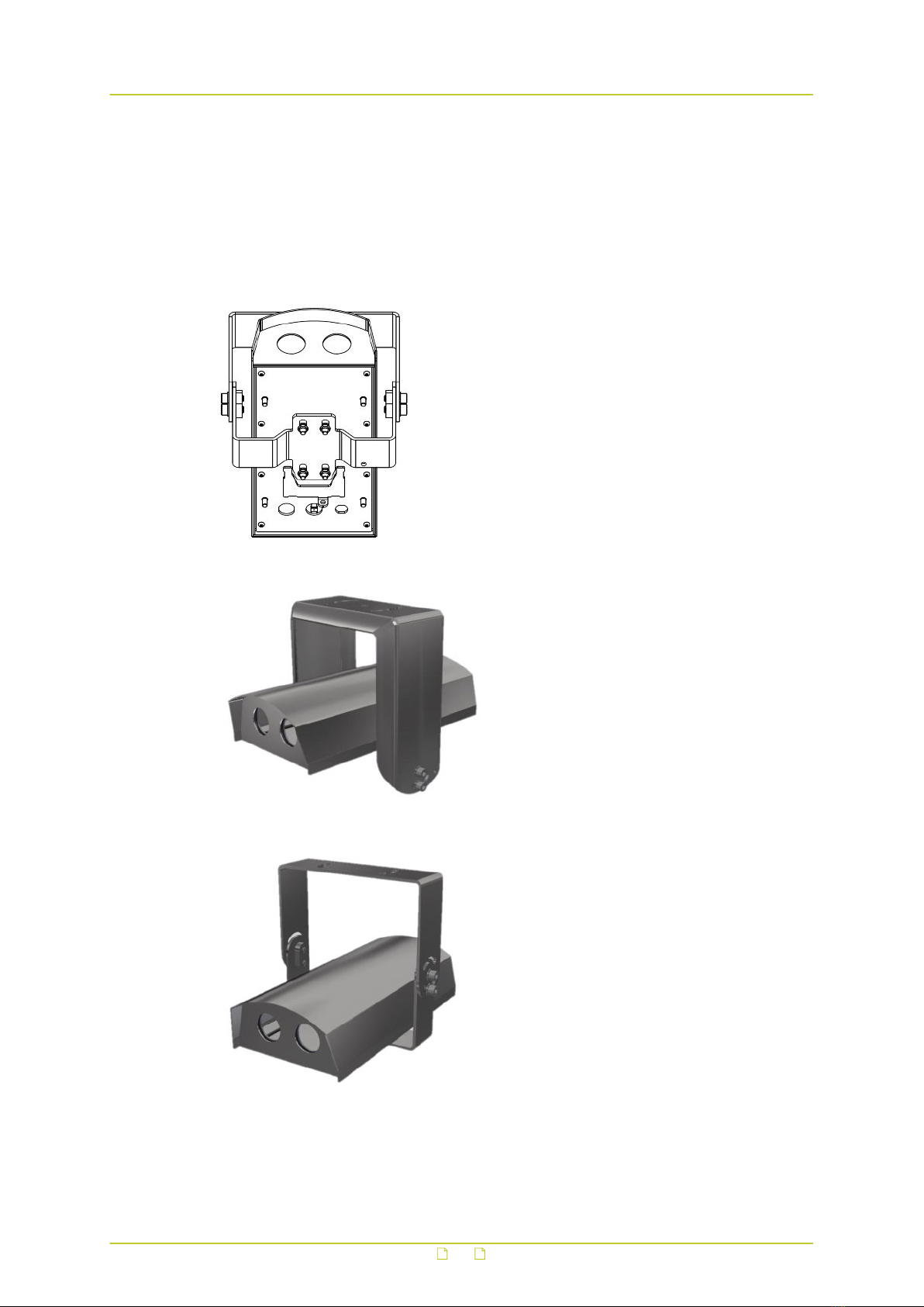
XCUCM01 Heavy duty ceiling mount for XCU Fusion
XCUCM02 Ceiling mount for XCU Fusion
Mount and connect
16
5.2.2 Mount the ceiling mount
● When mounting the ceiling mount, use anchors and screws (M8) which are
appropriate for the mounting surface.
● Each anchor or screw must be able to hold 100 kg.
Attach the mount to the ceiling
1 Mark the drill hole positions (see the drilling templates below).
2 Attach the mount to the ceiling.
Attach the mount to a pole or wall (only for XCUCM02)
Apart from attaching the ceiling mount to the ceiling, ceiling mount XCUCM02 can also be
mounted on top of a wall or pole. In that case, turn the mount upside down so that the outer
bracket rests on the wall or pole.
1 Mark the drill hole positions (see the drilling template below).
2 Attach the mount on top of the wall or pole.
Drilling template ceiling mount XCUCM01 heavy duty
Drilling template ceiling mount XCUCM02
5.2.3 Mount the camera
Mount the sunshield (optional and only for XCUCM02)
1 Position the sunshield over the camera.
2 Align the nuts and bolts with the receiving holes on the sunshield.
3 Tighten the four locking nuts which fasten the camera to the sunshield.
Mount and connect
17
Attach the camera to the ceiling mount (ceiling mounting)
1 Position the camera bottom over the ceiling mount.
2 Align the nuts and bolts with the receiving holes on the ceiling mount (see the bottom
view below).
3 Lower the camera onto the ceiling mount.
4 Slide the camera into locking position on the ceiling mount.
5 Tighten the two locking nuts which fasten the camera to the ceiling mount.
Bottom view of properly mounted camera
XCU Fusion ceiling mounted on XCUCM01 heavy duty
XCU Fusion ceiling mounted on XCUCM02
Attach the camera to the ceiling mount (wall or pole mounting)
1 Remove the screws that fasten the inner bracket to the outside bracket and separate the
two brackets.
Mount and connect
18
2 Position the camera bottom over the inner bracket.
3 Align the nuts and bolts with the receiving holes on the bracket.
4 Lower the camera onto the bracket.
5 Slide the camera into locking position on the bracket.
6 Tighten the two locking nuts which fasten the camera to the bracket.
7 Position the camera and inner bracket inside the outside bracket so they form a ' U'
shape together.
8 Tighten the screws which fasten the inner bracket to the outside bracket.
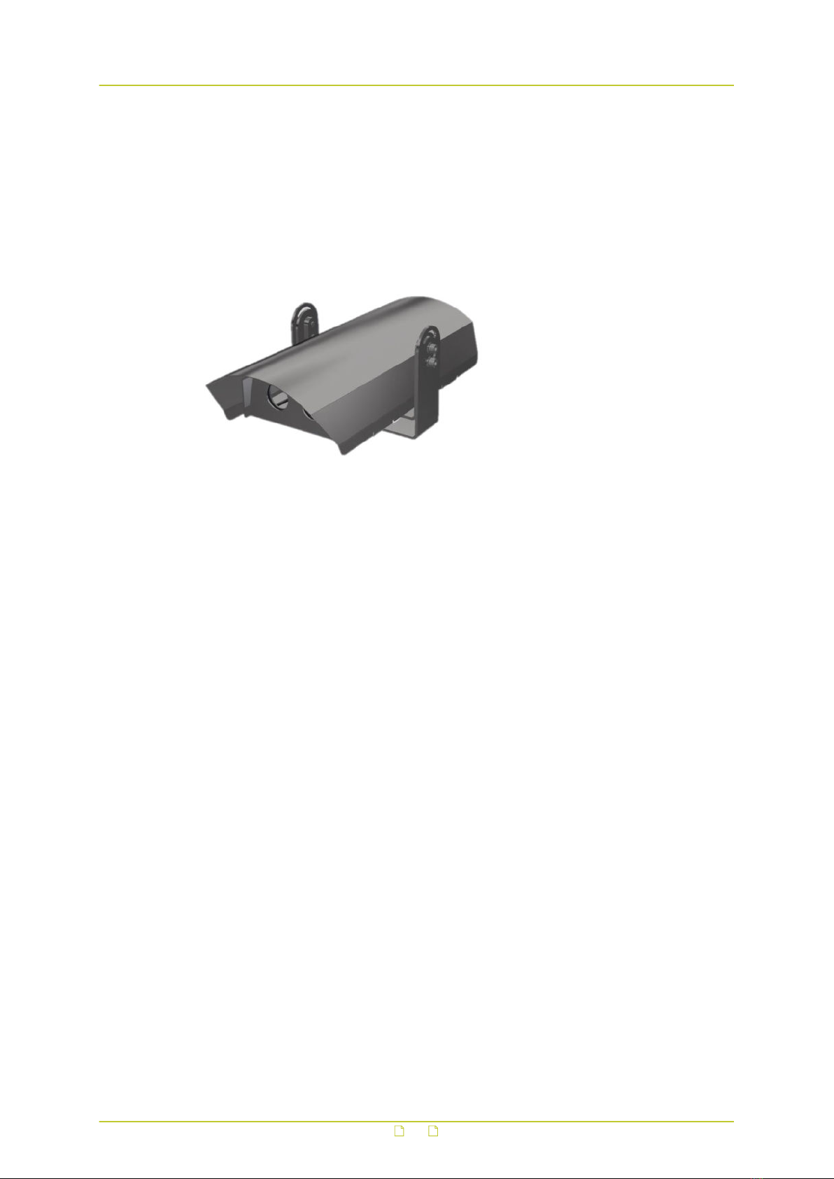
XCU Fusion wall/pole mounted on XCUM02
5.2.4 Connect to network and power
To connect the camera to the network and power, follow the instructions of Connect to
network ( on page 15) and Connect to power ( on page 15).
5.2.5 Check installation
Check if the unit and its mount are properly secured by the mounting bolts and screws.
Mount and connect
19

6 Maintenance
● Read and understand the following instructions before you clean or service the
unit.
● Use only original Siqura replacement parts.
● Observe the applicable standards when you inspect, maintain or repair the
equipment.
● Disconnect the power to the unit and contact Siqura support or the nearest
service centre whenever you detect damage or deformation to the equipment.
● If the product does not work properly, contact Siqura support or the nearest
service centre. Never attempt to disassemble the camera yourself. Siqura
does not assume any responsibility for problems caused by unauthorised
repair or maintenance.
Maintenance and inspection intervals
The XCU Fusion has been designed especially for the harsh environment of traffic tunnel
applications and requires little or no maintenance. The camera is fanless and does not include
any parts which are prone to wear and tear. Therefore, do not open the camera housing for
any maintenance activities. It is advised to inspect the glass window at a regular basis for
environmental pollutants such as dirt, grime or dust.
Routine activities
Regularly perform the following routine activities:
●Inspect the level of pollution on the glass window
Inspection frequency depends on the ambient pollution levels. Extremely polluted
environments may require more frequent inspections.
●Clean the unit (and the glass window)
Any pollution on the unit or the glass window can be rinsed off with water. You can use a
pressure washer. Do not use caustic or abrasive cleaning products.
●Inspect the mounting of the unit
Check if the mounting bolts and screws are still properly secured.
Extraordinary maintenance
The XCU Fusion does not require extraordinary maintenance.
20
Other manuals for XCU Fusion
1
Table of contents
Popular Laboratory Equipment manuals by other brands

RADWAG
RADWAG X2 Series user manual

Snibe
Snibe Maglumi 2000 manual

Bullard
Bullard Powerhouse installation manual

Andersen Sterilizers
Andersen Sterilizers Anprolene AN74i Installation guidelines

Agilent Technologies
Agilent Technologies 6460 Guide

Drucker Diagnostics
Drucker Diagnostics 842VES Service manual

ChemoMetec
ChemoMetec NucleoCounter NC-250 Cleaning guide

TestEquity
TestEquity 1007H Operation and service manual

Tuttnauer
Tuttnauer 2540 MKA Operation & maintenance manual

THORLABS
THORLABS LCC3111H user guide

LAGO
LAGO LX-18HR instruction manual

crest Optics
crest Optics X-Light V2 TP Installation and user guide


