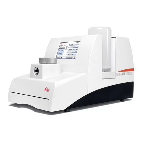
Fluigent OMI User manual

USER’S
MANUAL

(1) Power supply kit*
O-OMI-SK
*Socket depending on the region
WHAT IS INCLUDED
(1) OMI device
O-OMI-DEV
(1) Tablet
O-OMI-TAB
(3) Cartridge
O-OMI-CART
*Comes in sterile package
(3) Low resistance adaptor
O-OMI-LRCC
*Comes in sterile package
(3) High resistance adaptor
O-OMI-HRCC
*Comes in sterile package
(1) Air filter & pneumatic kit
O-OMIAF-CTK
(1) OMI connector & tubing kit
O-OMI-CTK
OMI single channel platform [O-OMISC-PTF]
Included in OMI standalone package

PRECAUTIONS
Do not place the product in an unstable location with a level surface
and a strong and stable support
Do not use other power supply than the one provided, it has been
carefully selected to meet the power requirements of Omi in all
configurations and to comply with all safety standards.
Aria is a perfusion system which automates perfusion or timed
injection protocols. It allows for the sequential delivery of up to
10 different solutions at the desired flow rate into a microfluidic
chip, perfusion chamber or petri dish.
Do not open or dismantle the Omi device.
Please refer all servicing to after-sales service
department (support@fluigent.com)
Prevent any objects or liquid from entering the Omi device, this may
cause a short-circuit failure or other malfunction. Failing to respect
this advice would:
• Expose you to direct current/voltage in case the device is under
voltage which may lead to severe damages
• Void device's warranty
• Discharge our company from any liability regarding physical or
device damages.
TABLE OF CONTENT
INTRODUCING OMI 6
SETTING UP 8
P 8
H 9
Power ON / OFF 9
Placing / Removing cartridge and adaptor 10
Pipetting solution 13
Pneumatic filter / External gas source 13
A 14
Installation 14
Key concepts 15
Registration 16
First login 19
Start protocol 24
ERROR & WARNING LIST 35
EMBEDDED DISPLAY 37
S 37
M 38
W / E 40
P / S 41
R / S 42
E 43
U 44
M / I 45
A 46
M 47
HARDWARE SPECIFICATIONS 48
TECHNICAL SUPPORT 48
WARRANTY TERMS 49
SAFETY & INFORMATION 50
NOTES 53

6 7
Omi is the first automated microphysiological platform, of the peristaltic
pump or syringe pump type, on the market dedicated to to sustain
cell culture or organ on chip model. Flexible, it has been designed
to interface with any type of chip. Compact, transportable (software
on tablet), autonomous (operates on battery), proof incubator, it is
perfectly suited to working conditions in a cell biology laboratory.
INTRODUCING OMI
INTRODUCING OMI
Omi can be used in single or dual perfusion mode to perform either
single channel perfusion for blood vessel reproduction for example
or co culture for liquid/liquid interfaces for gut on chip or blood brain
barrier reproduction by synchronizing two Omis with one organ on chip.
S
D
Omi can be used in single mode to perform for example single
channel perfusion for blood vessel reproduction
Omi can be used
in dual mode to
perform co culture
for liquid/liquid
interface.
Cells
Channel
Flow
Membrane
Cells (type 1)
Channel 1
Flow 1
Cells (type 2)
Channel 2
Flow 2

8 9
SETTING UP
Plug the power source to one of
the two power ports. The battery
will then start charging.
(Note that the battery will then
be able to run)
P ON
SETTING UP
Communication between an Omi device and the mobile application
on your tablet can be done in two ways:
P
H
Bluetooth: A direct connection between the device and the tablet
is made. The tablet must have its Bluetooth activated and its
geolocation activated as well (this is a current requirement from
Android OS).
Wifi: The device sends its state via a remote server that is forwarding
the information to both the web server and the tablet. Omi devices
must be connected to a Wifi network to make it work.
When Bluetooth is set as the favorite communication method the Omi
devices can still send information via Wifi in parallel. So one method does
not prevent the other. For your information, Bluetooth information is
updated every second for a set of maximum 6 devices in parallel. When
there are more than 6 devices, only the first 6 devices can be updated
on such frequency, the others will be updated every 30 seconds.
Aria is a perfusion system which automates perfusion or timed
injection protocols. It allows for the sequential delivery of up to
10 different solutions at the desired flow rate into a microfluidic
chip, perfusion chamber or petri dish.
Note: Omi devices cannot connect to a Wifi network protected by a login/
password access (e.g. eduroam) or to a Wifi network using the 5GHz
band. Some places also ask for a MAC-based recognition of the devices
connected to a Wifi network to allow their access to the internet. Check
with your IT department whether this is applicable to your Omi devices.
You can then use the other power port in combination with the Power
Link cable to power up to 4 other Omis in a daisy-chain configuration.
Finally, press the back button for
at least 2 seconds. The screen
should then turn on.
To power Omi OFF, press the button for a few seconds. The screen will
turn OFF. If the power source is plugged, the battery will then still be
charging.
P OFF
Power source Power link cable
Power in
"click"

10 11
SETTING UP
P/R
SETTING UP
To place a cartridge, slide the two level sensing rods in the cartridge
holes, and gently push it until you hear a double “click”, meaning that
the side bolts locked it.
Pay attention to the cartridge orientation: the rounded notch
should align with the machine.
Check that it is correctly locked by gently trying to pull it out. It
should stay in place horizontally and the two buttons aside should be
oriented inwards.
To unlock the cartridge, push the two aside buttons outwards and
simultaneously. The cartridge should automatically be ejected. You
can then gently slide it out.
When to use the high or low resistance adaptor
1Cartridge holes
2Round alignment notch
3Level sensor rods
4Lock buttons (inward to engage bolt)
1
4
4
2
3
Low resistance adaptor can
be used for experiment where
high flow rate is needed. The
low resistance adaptor allows
to reach up to 1ml/min flow rate
with Omi (without taking the
chip design and resistance into
account).
High resistance adaptor can be
used for experiment where low
flow rate is needed. The High
resistance adaptor allows to
reach up to 100µl/min flow rate
with Omi (without taking the
chip design and resistance into
account.

12 13
SETTING UP
When the cartridge is in place, the adaptor can now be positioned.
The adaptor allows the Omi to be compatible with both low and high
resistance Organ-on-chip chips for better versatility.
Low resistance adaptor
High resistance adaptor
Once the adaptor is in place, connect the chip using the provided
adaptors.
P
To fill the reservoir with a solution once the cartridge is inserted,
remove the cap and use a pipette to transfer the solution.
The volume of liquid in the reservoir should be between 500µl and
4ml. Above or below that, the reservoir will be considered empty or
overfilled, which can be a problem
After pipetting, the caps should be closed tightly to ensure there is no
leakage in the system (be sure the cap is equipped with its silicone
gasket).
P
Filter / External gas
source inlet
SETTING UP
We strongly advise placing the external filter in order to enhance the
internal pump lifetime.
To use an external gas source (like CO2, N2, or air from outside
the incubator), plug tubing on the luer port on the filter using an
appropriate luer connector. Please note that the gas source should be
at atmospheric pressure. The internal pump consumes up to 150ml/
min of gas.

14 15
All Omi users are part of
a team. Within this team,
devices, layouts and protocols
will be shared to allow
different members of the
team to work synchronously
when necessary.
Devices designate all Omi apparatus that a user manipulates.
This is basically the hardware that will run your protocols. The list of
your team devices can be seen in “Menu” > “Devices”.
A layout is a virtual group of devices that can be monitored by the
mobile application at a rather high frequency.
While all devices that are part of a layout can be seen and controlled,
a device that would not be part of the current layout will be hidden.
This can be useful to sort your workspace based on the type of
experiments your devices are running or based on their location in
your incubator for instance.
Note that a unique layout can be used for up to 12 devices. Only
6 devices maximum can be monitored simultaneously at high
frequency. The remaining devices will be easily accessible but
will be monitored at a lower frequency (about every 30 seconds in
Bluetooth mode). You can check what is the current layout used by
the application, load another one or create a new one by going to
“Menu” > “Layouts”.
A protocol is a sequence of steps that you want to perform in an
automated way.
When sent to a device, a protocol is automatically started and will
read and execute the protocol sequence, step-by-step. A protocol can
be created or edited via “Menu” > “Protocols”.
The Omi mobile application is available via the Google Play Store of
any Android-based tablet. To find it, simply search for “Omi”, access
the application page, check that the publisher is “Fluigent SAS” and
press “Install”.
SETTING UP SETTING UP
A
I
Use the link below or flash the QR code
to download the application:
https://play.google.com/store/apps/
details?id=com.fluigent.omi&pli=1
K
Devices LayoutsProtocols
Team
Admin
UserUser

16 17
SETTING UP
Launch Omi mobile application
Open Omi mobile application. On the first page, click on register.
On the registration page, fill in the required information.
If all the information is filled in correctly, a message will pop up to
confirm the Omi's registration and a confirmation link with the account’s
information summary will be sent via email. Click the confirmation link
(or copy-paste the URL in a browser) to verify the email used. Once
done, different features of the mobile application are now accessible.
To use the mobile application, you must create an account. It
requires access to the internet and can be done either via the mobile
application itself or via the Omi website (https://omi.fluigent.com).
To register you will need one of two pieces of information:
The serial number of one of your Omi device, can be found on the
tag below the device:
or a team invitation that someone sent to you to integrate his or
her team.
SETTING UP
R
QR code
containing
the P/N and
S/N

18 19
Launch Omi service web
Open in a browser https://omi.fluigent.com. On the login page (see
below), click on “Register”.
On the registration page, fill in the required information.
Users can login via the web interface before verifying the email used
but will only have access to a very limited set of options that include:
Editing information
Deleting the account
Requesting to resend the confirmation link
SETTING UP
SETTING UP
When first logging in to the Omi mobile application, users will be
guided through a 4-step tutorial in order to run your first protocols.
As a first step, a successful login will display the settings page.
Settings
Choose your preferred
communication
method between the
mobile application
and the devices.
Two methods are offered, either a Bluetooth-based communication,
where a direct connection is made via Bluetooth between the device
and the tablet, or a Wifi-based communication, where the device
sends its data to a remote server that forwards it to the tablet. To use
this second method, users must provide the Wifi settings in the next
section (“Omi devices network”). This consists of an SSID and the Wifi
password. Click the button next to the Wifi SSID field to scan nearby
networks and select yours. Finally, the Wifi password will always have
to be filled in manually.
Note that this page also allows users to receive information like your
current team ID, user ID, application version and a direct link to the
web server. It is also possible to change your current team by entering
another team code.
Press “Save” or “Skip” after filling in the settings to view the second
step of the tutorial.
F -

20 21
SETTING UP
Hardware useful information
This page illustrates how to prepare your devices for the next step.
As explained in Power ON, the page displays some explanations on
how to turn ON your Omi devices. It also illustrates how to get the
Bluetooth address of all your devices via the embedded screen.
Press “Next” to access device pairing.
Device pairing
When the page loads, a background process analyses all surrounding
Bluetooth devices to look for Omi devices. Once done, if new devices
have been detected, a message will appear and allow users to pair all
devices at once. If so, a list with nearby devices and their Bluetooth
addresses will show.
SETTING UP
Users have the possibility to change each device name (by default
“Fluigent Omi”) and to provide the Wifi information that the devices
will use to connect to the internet. Press “Pair X device(s)” to pair the
selected devices. Once done, your devices should appear in the list and
have “Paired” as the status. If you joined a team that already registered
devices previously, all team devices will appear here.
Press “Next” to reach the last step of the process.

22 23
SETTING UP
SETTING UP
Layout creation
A layout is a group of devices that are monitored simultaneously. Any
device that does not belong to the active layout (only one layout can
be active at a time) will not be visible in the homepage and won’t be
monitored. This allows users to create a group of devices based on
different criteria like experiment types, spatial localisation, users, etc.
It is also possible to create a unique layout that contains all devices a
team possesses.
After entering your layout name, users have the option to add a
new chip. A chip can possess 1 or 2 channels and will therefore be
associated by either a single Omi device or two. Associating 2 devices
to a single chip allows the use of dual perfusion mode where each
device addresses a different channel of the chip (see …). Note that you
can add up to 12 devices on a single layout, therefore it may include a
maximum of 6 to 12 chips.
Each new chip added must be associated with at least one device. To
do so, press the chip area, and the association page will be displayed.
If you have successfully paired new devices in the previous step, (see
Device pairing) they will be available in the drop down list after a short
loading time.
To add and pair new devices, press “Add a new device”.. This will activate
the “Associate” button and display the editor page, where the device
should now appear in the chip section.
After adding all devices needed for your layout, press “Load” to make
use of this layout. A popup will notify you that going forward will close
the tutorial.
Press “Finalize” to finish the process.
Note that after finalizing the tutorial, it will not be accessible
anymore upon restarting the application. To follow this tutorial
again, you can go to “Menu” > “Settings” and press “Run tutorial”.

24 25
Device information page
This page will display more details about the selected device (or
devices in case of a dual perfusion system).
Among the new information displayed, added to the ones mentioned
in the previous section, you will find:
The warning and/or error messages (if any - see Error and Warning list for
more details)
The device name
The device wifi connection status
The device firmware version and a notification about available updates
A list of all protocols available and the option to create a new one,
and to edit/run the selected protocol
A brief overview of the selected protocol steps and parameters
When using the application for the first time, no protocol will be
available, one must create a new one to be able to run it on a device.
To do so, press “New”.
SETTING UP
Visualization of layout - Home page
Upon starting the application, or after finalizing the tutorial, you will
be brought to the home page. On this page, all devices of the current
layout are visible.
A maximum of 6 devices can be seen at the same time. If your layout
contains more than 6 devices, the remaining devices can be accessed by
swiping from right to left. Some basic information about each device's
current state is displayed if the mobile application can communicate
with it. Among the available information from the homepage:
Name of the chip
Date and time of the last message received for this device
Current step executed by the device (if any) and current state of
the device
Warning or error notification via the device illustration background
(red for errors, orange for warnings)
Every device on-screen is monitored live, meaning that its status is
updated every second with a Bluetooth connection, and every 3 seconds
when communicating via Wifi. To access more information about a
device and run a protocol, you can press its illustration.
SETTING UP
S

26 27
SETTING UP
Protocol editor
When accessing the protocol editor, a configuration window asks
whether to load an existing protocol or create a new one.
To create a new protocol, some information must be provided:
(opt.) Name of the protocol
(opt.) Description of the protocol
Perfusion mode (Single perfusion, Dual perfusion) - if Dual perfusion is selected:
- Dual mode (Sequential, Synchronized)
Default control type (Flowrate & Time, Volume & Flowrate, Volume & Time) - can be
changed for each step individually
Automatically insert pre- and post-processing steps to the protocol
Use of shear parameters instead of flow rate - if selected, a new set of parameters
will appear:
- Dynamic viscosity of the liquid (in mPa.s)
- Channel geometry (Circular or Rectangular)
- Diameter (in µm) OR Height/Width (in µm)
Once you’ve filled in all required parameters, press “Create” to start
editing your protocol.
TIP: For your first protocol, we strongly advise inserting the pre- and post-
processing steps. If this is problematic, at least add the Calibration step to
properly calibrate the liquid level sensors. Without a proper calibration, you
may encounter errors that will block your protocol.
Single perfusion mode
If you’ve selected to add pre- and post-processing steps in the
configuration window, they will appear. To add a new step, select one
on the left side.
Pressing it will add the steps to the list and, if this step is editable, a
parameter window will be opened.
SETTING UP

28 29
SETTING UP
The top bar provides some information about the current protocol
and some basic controls/ From left to right:
Name - can be changed via the editing icon at the right of the field.
Total time - Cumulated time of the protocol based on all the steps present in the
step list.
Settings - Open the configuration window (as presented previously - see Figure X).
Reset - Delete all steps of the current protocol and reset it, automatically open the
configuration window afterwards.
Open - Open a window that presents all protocols saved previously either remotely
(team protocols) or locally.
When selecting a protocol, some basic information are displayed:
- Name
- Description
- Mode (single or dual)
- Modified by
- Modified on
- Estimated duration
Save - Save the current protocol locally, a popup will ask to upload the protocol to
the cloud.
SETTING UP
This window allows you to tune the
step parameters:
Control type (Flowrate & Time, Volume
& Flowrate, Volume & Time) - by default
the control type selected in the protocol
configuration window
Volume (in µl or ml)
Flow rate (in µl/min or ml/min)
Duration
Source & Destination - cannot be changed, illustrate the input and output reservoir(s)
for this particular function
Flow pattern (Steady, Sinusoidal, Slope or Step) - if different from “Steady”, a new
set of parameters will appear:
- Period (in s) - number of seconds between two patterns
- Min flowrate (in µl/min or ml/min) - lowest value targeted by the flow pattern
- Max flowrate (in µl/min or ml/min) - highest value reached by the flow pattern
Once you’ve filled in all required parameters, press “Ok”.
To change a step position, you can either drag and drop it to
its new position, or press one of the up/down arrows to move it
upward/downward.

30 31
SETTING UP
Run a protocol - Device page
The newly created protocol should now appear in the list. Select it, and
details will appear in the “Experiment info” section. Whenready, run the
protocol by pressing “Run”. It may take up to 3 minutes (depending on
your protocol length) to send the protocol information to the device(s).
Once done, you will be notified and the page should change and switch
to the protocol first step page.
There are two types of pages depending on the type of step the device
is currently running:
1. Blocking step page
In those steps, a manual operation is necessary to go through the
step. They are usually divided in several sub-steps that require either
a confirmation from the user, or an action with the Omi device. The
blocking steps are: Calibration, Sterilization, Loading and Cleaning.
Dual perfusion mode
In Dual perfusion mode, the step list will look slightly different.
Here, every step is automatically duplicated to be run on two devices (X
and Y) in parallel. Depending on the mode you have chosen (“Sequential”
or “Synchronized”) users have the option to synchronize each step, one
by one. Press the “Sync” checkbox to activate or not the synchronization
of a step between the two devices. When synchronized, a step won’t start
on a device (X) if the same step has not been reached yet by the second
device (Y). This ensures that a particular step is started at the exact
same time on two devices used in dual perfusion mode. Any change
you make in the step parameters of one device will be automatically
reflected in the step parameters of the other device.
TIP: To use different parameters for the same step, duplicate the
step and delete it for one device in the first location, then delete it
for the other device in the second location. Note that in this case,
it's not possible to synchronize the step between two devices.
Once finished, save your protocol and press the top right button to pre-load the
protocol in the "Device page". You will be redirected automatically to this page.
SETTING UP

32 33
SETTING UP SETTING UP
2. Automatic step page
Those steps begin automatically and do not require, if no error occurs,
manual intervention from the user. The automatic steps are: Injection,
Sampling,Perfusion, Recirculation, Wait and Manual operation.
NOTE: A page is only updated when the information the tablet gets
from the device has changed. Do not expect a page to change
right after “Next”, “Stop”, “Pause”, etc. Users must account for the
time a command is sent to the device, processed, sent back by the
device to the tablet. Depending on the communication protocol,
Wifi or BLE, it can take between 1 and 5 seconds before the effect
of a command is reflected in the mobile application.
Run a protocol - Experimental summary
When a protocol is finished, a summary page is shown, containing:
Start time
End time
Data sync status - When reaching the experiment summary page, a verification is
made to ensure that no gap exist in the data records of 1) the tablet storage - Local
data - and 2) the remote server database - Server data. If any gap above 30 seconds
is found on either storage location, an indication in red and a synchronization button
are shown. Pressing the button will trigger the synchronization between either 1)
the Omi internal memory and the tablet storage or 2) the tablet storage and the
remote server database.
In the first case (Omi <->
tablet) a dedicated page
(see screenshot below) is
accessed and report the
synchronization status.
The second case (tablet <->
server) is rather fast and
only show a short waiting
icon while the data are
sent.

34 35
SETTING UP
ERROR & WARNING LIST
Name Description Possible solution
Low battery
level
The battery level is under 20% Plug-in your Omi device
Low wireless
signal
The device has difficulties accessing
the internet network. Bandwidth
and latency can be degraded
Move the Omi closer to a
Wifi router
Air leak in the
system
The device cannot pressurize
correctly the reservoirs leading to
reduced pressure and flow-rate
Check that all components
are properly sealed and that
no space exist between the
different components
Low liquid
level
The liquid level of one or more
reservoir(s) is low (under bottom
level sensor)
Fill in the reservoir(s)
reported as too low
High liquid
level
When a fluidic step is in progress,
one or more output reservoir(s) have
a high liquid level that could prevent
the correct execution of the step
when they are full
Empty the reservoir(s)
reported as too high
Error during
firmware
update
An error occurred during the last
firmware update
Try to update the firmware
again (device page). If the
error persists, contact the
support team
Wrong
command
received
The last command received could
not be processed
Try to send the last action
command again. If the
error persists, contact the
support team
W
Errors - If any error occurred during the protocol, a sorted list of
error(s) is created and can be accessed through an icon displayed
Statistics - To see how a property fluctuated along the protocol, press the graph
icon for the property being . A popup window will appear with a plot of the selected
property values during the experiment. Note that those values are only shown for
the automatic steps and are restricted, for performance sake, to 600 points over the
whole experiment. If more points have been recorded, the 600 points are selected
every X frames to report the overall trend.
To quit the experiment summary page, simply press “Finish experiment”.
A popup message will appear warning that finishing an experiment deletes all
related data from the tablet and device storage space. If data frames have been
saved on the remote server, they can be accessed at any time by logging in via
the web interface.
Data storage
Omi automatically stores data every 30 secondes during an experiment. The storage
capacity is up to 10 days of data.
Retrieve experiment details
In the event of a local database deletion because of the use of a new tablet, an application
re-installation or an application upgrade going wrong, the information of all running
experiments is lost in the tablet database and the monitoring of the related devices is
impossible. However, it is still possible for a user to retrieve the information related to
his running experiment via the Sync Live Experiment page. On this page is presented
all current running experiments of the user. Team administrators will be able to access
all the team running experiments as well. Choose a running experiment from the list
and press “Load” to have its layout and experiment details loaded.
Upon a successful
synchronization you
will be automatically
redirected to the
Home page with the
layout used to run the
experiment loaded.
Now, accessing a
device with a running
experiment will be
possible.

36 37
ERROR & WARNING LIST
Name Description Possible solution
Critical battery
level
The battery level is under 5% Plug-in the Omi
Missing fluidic
component
One of the following component is
not detected: Lid, cartridge, adaptor
Check that the Omi has
its cartridge and adaptor
correctly positioned and
that it is properly closed.
Unreachable
pressure
The requested pressure cannot be
reached by the device
Check that all components
are correctly closed and
that no space exist between
them
Unreachable
flow-rate
The requested flow-rate cannot be
reached by the device
Check that the pressure
value is consistent with the
requested flow-rate
Empty
reservoir
One or more input reservoir(s) is/
are empty
Fill in the reservoir(s)
reported as empty
Full reservoir One or more output reservoir(s) is/
are full
Empty the reservoir(s)
reported as full
Pump stopped The pressure pump has stopped
working
Try restarting the device. If
the error persists, contact
the support team
No liquid
detected
System clogged during a
recirculation step
Try to launch a cleaning
step or change the
cartridge
E EMBEDDED DISPLAY
S
While Omi key functions (such as protocol editor) are only avail-
able via the mobile app or the web service, main information
and access to basic controls are found in the embedded screen.
At startup, a splash screen with the Omi logo is displayed for about
5 seconds.

38 39
EMBEDDED DISPLAY
M
The first page to
be displayed is the
main screen which
indicates the state of
the device.
This screen contains
the following
elements :
1The top navigation bar can be found on every screen and always indicates from
left to right :
- The state of the wifi : connected or disconnected
- The state of the bluetooth : paired or unpaired
- The name of the device
- The percentage of the battery charge left
- A pictogram that indicates if the battery is charging or gives a visual
representation of the remaining charge
2The bottom navigation bar can also be found on every screen but its content will
depend on the displayed screen. When no experiment is loaded, userswill only be
able to press the menu button that links to the Menu screen.
3The fluidic system illustration indicates the level of the 4 reservoirs and the input
and output reservoirs with corresponding flowpath.
4At startup, an update button will be blinking for [xx] seconds if a new hardware
update is available. Pressing this button will the update screen. Newly available
updates can be found at any time on the Information screen.
5A warning and error pictogram will be displayed if an error or a warning is
occuring. This pictogram will be yellow if only warnings are occurring and red
if there is at least one error. Pressing this button will display the Warning / Error
screen to show error and warning messages.
EMBEDDED DISPLAY
When and experiment is running, the bottom navigation bar indicates :
The measured flowrate value
The computed shear stress value
The name of the running step and its position in the experiment
The step percentage of completion
Press any of these values to open the Experiment summary screen.
If the experiment is running, press the pause button to display
the Pause / stop screen. If the experiment is paused, a play button
can be found in place and will drive you to Resume / stop screen.
1
2
3
4
5
This manual suits for next models
1
Table of contents
Other Fluigent Laboratory Equipment manuals
Popular Laboratory Equipment manuals by other brands

Bruker
Bruker BPHG 90 user manual

Molecular Devices
Molecular Devices MultiWash+ user guide

Thermo Scientific
Thermo Scientific Dionex ICS-5000 Operator's manual

Grace Medical
Grace Medical 990-001 quick start guide

Gilson
Gilson Power Carrousel user guide

Agilent Technologies
Agilent Technologies Labware MiniHub G5584A user guide

Thermo Scientific
Thermo Scientific MaxQ Mini 4450 series manual

Hanil
Hanil J1250 user manual

VWR
VWR VAPOUR-Line lite instruction manual

OMEGA AIR
OMEGA AIR TACm Series Installation and operating manual

Eurotherm
Eurotherm 394 user guide

Agilent Technologies
Agilent Technologies ZORBAX RRHT Series user guide