Drawell DW-ATN-300 User manual

Automatic Kjeldahl Apparatus
DW-ATN-300
Drawell International Technology Limited
Shanghai Drawell Scientific Instrument Co.,Ltd
Add :Suite 1506,Lane581 XiuChuan Rd.,PuDong New Area,Shanghai,China
Tel/ Fax: 0086 21 50966080
Web : www.drawell.com.cn
Email : [email protected]

Table of Contents
Safety Instructions ················································································1
Packing List ·······················································································3
I. Descriptions ·····················································································4
II. Working Principles ··············································································4
III. Technical Indexes of the Apparatus····························································5
IV. Apparatus Structure ···········································································6
V. Installation Method ·············································································7
5.1 Pre-installation Check ····································································7
5.2 Installation Conditions ·····································································7
5.3 Installation Steps ·········································································7
5.4 Debugging ················································································7
VI. Application Methods and Steps·································································8
6.3 Flow Calibration ············································································9
6.4 Program Settings ············································································9
6.5 Manual Distillation ·········································································10
6.6 Automatic Distillation ······································································11
VII. Reagent Preparation Method···································································12
VIII. Precautions for Use of Apparatus····························································13

- 1 -
Dear User:
Thank you for choosing our products. It is recommended to carefully read this User’s Guide prior to
startup to get a satisfied effect. Please contact us for any questions and we will offer warm-hearted service to
you.
The User’s Guide is prepared with efforts of all technical workers, and the trial version has been
completed. Due to limited capacity, there may be some unclear expressions and omissions, your suggestions
and recommendations will be highly appreciated.
Safety Instructions!
Danger!!! Property or personal injuries may be caused, please use the machine as required!
Special power supply Reliable grounding Flammable and explosive No transformation
1. Please use the power supply and voltage conforming to the product requirements.
2. The applicable voltage for the equipment is AC220V/50HZ.
3. The product shall be reliably grounded and kept away from electromagnetic interference source (zero line
or neutral line can’t be used as the ground line).
4. The product shall be applied with the independent power socket; the plug and socket shall be well
grounded.
5. If the product is in operation, it is not allowed to plug in or plug out when the power switch is not turned
off.

- 2 -
6. It is forbidden to repair the product without permission; in case of repair entrusted by the company, the
professional staff shall be employed for guidance.
7. The working environment shall be free from dust and flammable and explosive gases.
8. The working environment shall be of 10℃-45℃ and relative humidity less than or equal to 80%.
9. The apparatus shall be installed in the place without direct sunlight.
10. As the reagent and other solution are corrosive, safety appliances shall be equipped during operation for
safety.

- 3 -
Packing List
Please check and count the accompanied accessories
Articles in the host machine case
Host machine ⋯⋯⋯⋯⋯⋯⋯⋯⋯⋯⋯⋯⋯1
User’s Guide⋯⋯ ⋯⋯⋯⋯⋯⋯⋯⋯⋯⋯⋯⋯1
Product Warranty Card ⋯⋯⋯ ⋯⋯⋯⋯⋯⋯⋯⋯⋯⋯⋯1
Product Qualification Certificate ⋯⋯⋯⋯⋯⋯⋯⋯⋯⋯⋯⋯⋯1
Accessories in the accessory box
Distilled water inlet pipe (6mm*1.5m) ⋯⋯⋯⋯⋯⋯⋯⋯1
Alkali liquid inlet pipe (6mm*1.5m) ⋯⋯⋯⋯⋯⋯⋯⋯⋯1
Boric acid solution inlet pipe (6mm*1.5m) ⋯⋯⋯⋯⋯⋯⋯⋯1
Waste distilled water pipe (6mm*1.5m) ⋯⋯⋯⋯⋯⋯⋯⋯⋯1
Condensed water inlet and outlet pipes (8mm*2.5m) ⋯⋯⋯⋯1 for each
Digestion pipe (40*300mm) ⋯⋯⋯⋯⋯⋯⋯⋯⋯⋯⋯1
Gloves ⋯⋯⋯⋯⋯⋯⋯⋯⋯⋯⋯⋯⋯⋯⋯⋯⋯⋯⋯⋯1pair
Power line (1.8m) ⋯⋯⋯⋯⋯⋯⋯⋯⋯⋯⋯⋯⋯⋯⋯1

- 4 -
I. Descriptions
Kjeldahl method is a classic method for nitrogen determination. Currently, the Kjeldahl method is
frequently applied for determining the nitrogen content of the soil, foods, agricultural products, feeds and
other substances. When this method is applied for the sample determination, three processes including
digestion, distillation, and titration will be gone through, and the distillation is an important process in
Kjeldahl method.
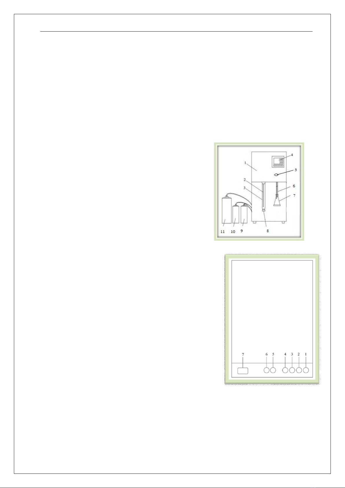
ATN-300 Automatic Kjeldahl Apparatus is a kind of automatic system researched and development
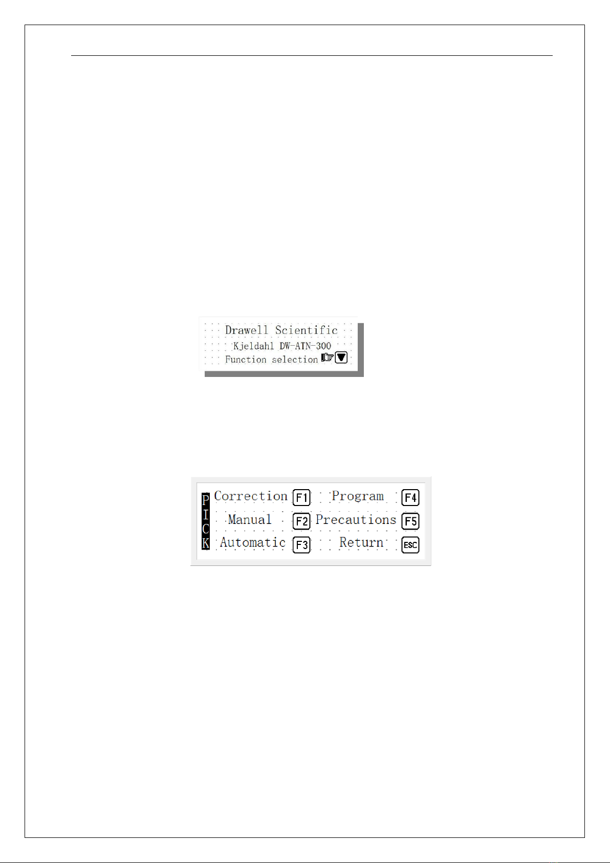
based on the classic Kjeldahl method, which is featured by user-friendly operation and easy learning due to
application of the Chinese menu and man-machine interface.
With two parts of the manual distillation and automatic distillation, ATN-300 is available for manual and
automatic water filling, alkali filling, acid filling, and distillation, which brings large convenience to the
laboratory personnel.
The automatic part of ATN-300 can save ten kinds of different combinations for water filling, alkali
filling, acid filling, and distillation time for setting and application by the user.
ATN-300 has applied the British self-sucking pump method for liquid feeding rather than the inflatable
method applied by many domestic manufacturers, which can place the liquid feeding barrel under the control
console and select the liquid feeding barrel with large capacity.
ATN-300 has been furnished with numerous protection measures, such as the distillation tube absence
protection (no heating or distillation without distillation tube); steam generator overpressure alarm protection
(shutdown and alarm in case of abnormal pressure); steam generator water shortage protection, and earth
leakage protection, so as to ensure safety of operators.
II. Working Principles
When all samples are digested, the distillation can be performed after having been cooled down to the
room temperature. The principles of the distillation process are as follows:
(NH4)2SO4+NaOH=Na2SO4+2H2O+2NH3↑
Under the alkalic conditions, separate the ammonia with the high temperature steam; after that, collect it
with the conical flask containing boric acid absorption liquid (containing mixed indicator); lastly, perform

- 5 -
titration with sulfuric acid or hydrochloric acid.
III. Technical Indexes
3.0. Measuring range: 0-250mg N
3.1. Distillation speed: ≈15——20ml/min; ≤8-5min/sample
3.2. Recovery rate: 99.9±0.5%
3.3. Distillation time: Ranging from 0 to 999s
3.4. Cooling water consumption: 1.2L—2.4L/min
3.5. Amounts of water filling, alkali filling, acid filling: 0—99ml
3.6. Sample weight: Solid<6g, liquid<30mL
3.7. Operation mode: Dual modes of manual distillation/automatic distillation
3.8. Automatic distillation mode: Ten kinds of distillation programs
3.9. Alarm and shutdown temperature: ≈120℃
3.10. Power voltage: AC220V / 50HZ
3.11. Maximum power: 1600w
3.12. Maximum current: 7.5A
3.13. Overall dimensions: 330mm*380mm*780mm

- 6 -
IV. Apparatus Structure
The system is mainly composed of the microcomputer controller, steam generator, distillation system,
and liquid filling system.
Figure of the Front-side Structure of the Apparatus (see Figure 4-1)
1- Front cover
2- Steam tube
3- Digestion pipe
4- Liquid crystal display
5- Power switch
6- Distillate outlet pipe / boric acid filling pipe
7- Conical flask
8- Digestion pipe tray
9- Acid liquid barrel
10- Alkali liquid barrel
11- Distilled water barrel
Figure of the Back-side Structure of the Apparatus (see Figure 4-2)
1- Distilled water inlet
2- Alkali liquid inlet
3- Boric acid solution inlet
4- Waste liquid outlet
5- Condensed water outlet
6--Condensed water inlet
7-- Power socket
The method is as follows:
Figure 4-2 Schematic Diagram of the
Back-side Structure of the Apparatus

- 7 -
V. Installation Method
5.1 Pre-installation Check
After the apparatus is unpacked, please check all accessories for damages according to the “Packing List”; if
any damages are discovered, please timely contact with the company (please reserve the damaged parts).
5.2 Installation Conditions
(1) The apparatus shall be installed in the working environment with the room temperature of 10-45°C
and relative humidity less than or equaling to ≤80%; abrupt temperature changes shall be avoided.
(2) The power voltage of the apparatus shall be AC220V/50HZ; reliable ground wire and independent
power socket ≥10A shall be applied.
(3) The apparatus shall not be installed in the too humid place with direct sunlight or dust.
(4) The apparatus shall be installed in the place close to the water source and drain tank.
(5) The water supply shall meet the requested water pressure and water temperature conditions (cooling
water pressure: 0.15Mpa, cooling water temperature: lower than 18°C).
(6) The drain tank shall be 10cm lower than the apparatus outlet to ensure a smooth drainage.
(7) As the equipment is a kind of precise apparatus; acute vibration or transverse and upside-down
placement shall be avoided.
5.3 Installation Steps (refer to Figure 4-1 and Figure 4-2)
(1). Place the apparatus on a stable experiment table.
(2). Connect one end of the “condensed water inlet pipe” with the “condensed water inlet” of the host
machine and another with the tap water valve.
(3). Connect one end of the “condensed water outlet pipe” with the “condensed water outlet” of the host
machine and another with the pond.
(4). Connect one end of the “waste liquid pipe” with the “waste liquid outlet” and another with the waste
liquid barrel or the pond.
(Note: It is unnecessary to frequently drain or change the distilled water in the steam generator, which is
necessary when impurities occur or the apparatus is not used for a long time.)
(5). Connect one end of the “distilled water pipe” with the “distilled water inlet” of the host machine and
another with the “distilled water barrel”.
(6). Connect one end of the “alkali liquid pipe” with the “alkali liquid inlet” of the host machine and another

- 8 -
with the “alkali liquid barrel”.
(7). Connect one end of the “boric acid pipe” with the “boric acid inlet” of the host machine and another with
the “boric acid barrel”.
VI. Application Methods and Steps
Pour the reagent which is prepared based on “VII” in page 9 into the container.
6.1. Plug the power plug into the socket.
The display on the liquid crystal display after startup is shown in the Figure 6-1.
Function selection
6.2. Press “▼” key to enter the “function selection” page: See Figure 6-2.
Figure 6.2 Function selection
F1:Correction-Flow correction F2:Manual-Manual distillation
F3:Automatic-Automatic distillation F4:Program-Program setting
6.3. Flow Calibration
Prior to flow calibration, connect with the container; after that, press “F6”, “F7”,“F8” keys for several times
to fill the pipeline with liquid.
In the “function selection” page, press “F1” key to enter the “flow calibration” page: See Figure 6-3.
Figure 6.1 Schematic
Diagram of the Switch

- 9 -
Flow-Flow Calibration
F6:Alkali-Alkali flow calibration 12.3 S
12ml:Calibration value 12ml
F7:Acid-Acid flow calibration 12.3 S
F8:Water-Water flow calibration 12.3 S
A. Alkali flow calibration: Connect the graduated cylinder
(about 100ml) with the alkali filler (by the side of the steam tube,
as shown in the Figure 6-4); after that, press “F6” key to select
the alkali flow calibration. After the operation is ended,
record the alkali solution volume in the graduated cylinder.
B. Water flow calibration: Connect the graduated cylinder
(about 100ml) with the water filler (same as that for alkali,
as shown in the Figure 6-5); after that, press “F8” key to select
the water flow calibration. After the operation is ended,
record the distilled water volume in the graduated cylinder.
C. Boric acid flow calibration: Place the “distillate outlet pipe” into
the graduated cylinder; press “F7” key to select the acid flow
calibration. After the operation is ended, record the boric acid
solution in the graduated cylinder.
D. Press “SET” after above steps are completed.
E. Input the recorded volume (mL value) into the corresponding “calibration value”.
F. Press “ENT” key after input for save and exit; here, the calibration is completed.
(Note: The factory calibration of the product is performed by distilled water; as the flowing volumes of the
liquid with different concentrations and proportions will be different at the same time, the user is
Figure 6-4 Schematic Diagram for
the Flow Calibration
Screen
Water filling and alkali filler
Graduated cylinder
Distillate outlet pipe
Distillation tube
Figure 6.3

- 10 -
recommended to perform re-calibration according to actual conditions.)
6.4. Program Settings
The “program” refers to different “combinations” for “water filling, alkali filling, acid filling, and
distillation time”, and the machine can save20 kinds of different “combinations”.
Press “F4” in the “function selection” page to enter the “program settings” page: See Figure 6-5.
Figure 6-5
Program Settings
Water 12 ml: Water filling amount 12 ml Alkali 12ml:Alkali filling amount 12 ml
Acid 12ml:Acid filling amount 12 ml Time 123s:Distillation time 123 S
A. Press “SET” key to perform program parameter settings.
B. After each setting, press “ENT” once for confirmation, using the following sequence:
C.SET ▲, ▼Program X selection ENT Water filling amount ml ENT
Alkali filling amount ml ENT Acid filling amount ml ENT
Distillation time S ENT ALM.
(Remember!!! After pressing “ENT” after completing each program setting, “ALM” must be pressed for
saving; or else, the program is invalid.)
6.5. Manual Distillation
Press “F2” in the “function selection” page to enter the “Manual Distillation” page: See Figure 6-6.

- 11
-
Figure 6-6
F1:Acid-acid filling F2:Alkali-alkali filling F4:Water-water filling
Manual distillation: It means that “on” and “off” of the alkali filling, acid filling, water filling, and
distillation processes are completed through manual control.
A.Press “F1” to select the “acid filling”; when the boric acid solution in the conical flask reaches the
requirement, press “F1” again to stop the acid filling.
B. Press “F2” to select the “alkali filling”; when the solution in the digestion pipe reaches the requirement,
press “F2” again to stop the alkali filling.
C. Press “F3” to perform the “distillation”; when the distilled solution reaches the requirement, press “F3”
again to stop the distillation.
D. Press “F4” to select the “water filling”; when the solution in the digestion pipe reaches the requirement,
press “F4” again to stop the water filling.
E. Press “F5” drainage means to drain out water in the steam generator. When impurities occur in the steam
generator or the apparatus is not used for a long time, water in the steam generator shall be changed or drained.
(Note: It is unnecessary to frequently drain or change the distilled water in the steam generator, which is
necessary when impurities occur or the apparatus is not used for a long time.)
6.6. Automatic Distillation
The “automatic distillation” means one of the previously saved “twenty” programs will operate
automatically.
Press “ENT” in the “function selection” page to enter the “automatic distillation” page: See Figure 6-7
Figure 6-7

- 12 -
A. Press “▲” and “▼” to select the previous “20” programs. (The selected program will be operated; if no
selection is made, the previously operated program will be operated.)
B. Place the sample (boiling tube). If no boiling tube is placed, the program will not be performed to avoid
reagent or steam overflow.
C. Press “ENT” to operate the automatic distillation program, and the apparatus will run in sequence of “water
filling——alkali filling——acid filling——distillation (countdown)——ending”.
D. After the set distillation time (the distilled solution is about 100mL, with the duration of about 400S) is
ended, the “ticking-” alarm sound with about 2S will be sent, and the program is completed.
E. During the distillation process, “ALM” can be pressed to exit from the distillation program.
Note: Due to different cooling water temperature and flow of the places (users), the time for distilling the
liquid with same volume (such as 100ml) may be different; the users are recommended to perform trial
distillation for several times according to the actual conditions to master (set) the distillation duration.
VII. Reagent Preparation Method
7.1 Prepare 2L 30%~40% sodium hydroxide solution and pour it into the alkali barrel (suggestion: The 35%
sodium hydroxide solution is recommended, for it will not easily crystallize and block the pipeline in case of
changeable room temperatures).
7.2 The methyl red -bromocresol green mixed indicator (preparing based on the sector standard).
7.3 Prepare 2L 2% boric acid solution and pour it into the acid barrel; the mixed indicator and boric acid can
be mixed based on the sector standard and poured into the acid barrel. The mixed indicator can be mixed after
distillation and before titration.
Note: If the titration is applied with the ZDG-1automatic luminosity titrator; only the methyl red is required
for the indicator.
VIII. Precautions for Use of Apparatus
8.1 The preheating is needed after starting the apparatus; after that, directly enter the manual operation and

- 13 -
select distillation. And, it is acceptable that the steam tube discharges the steam for about 1min.
8.2 The water, alkali and acid calibration must be performed before using the apparatus.
8.3 The digestion pipe shall be well positioned to jack the rubber plug.
8.4 As the digestion pipe will be very hot after distillation, gloves shall be worn upon taking it down to avoid
scalding.
8.5 The condensed water must be opened during distillation.
8.6 The filled alkali must ensure the alkalinity of the digestion solution greater than or equaling to 11.
8.7 If the apparatus is not used for a long time in winter, water in the steam generator must be drained out to
avoid cracked steam generator.

- 14 -
Drawell International Technology Limited
Shanghai Drawell Scientific Instrument Co.,Ltd
Add :Suite 1506,Lane581 XiuChuan Rd.,PuDong New Area,Shanghai,China
Tel/ Fax: 0086 21 50966080
Web : www.drawell.com.cn
Email : [email protected]
Table of contents
Other Drawell Laboratory Equipment manuals

Drawell
Drawell DW-280A User manual

Drawell
Drawell DW-TDZ5-WS Installation manual

Drawell
Drawell CIC-D100 User manual

Drawell
Drawell TANK User manual

Drawell
Drawell LBI-175A-N User manual

Drawell
Drawell DW-T960 User manual

Drawell
Drawell TDD4-MC User manual

Drawell
Drawell DW-FD Sereries User manual

Drawell
Drawell B Series User manual

Drawell
Drawell DW-GI Series User manual