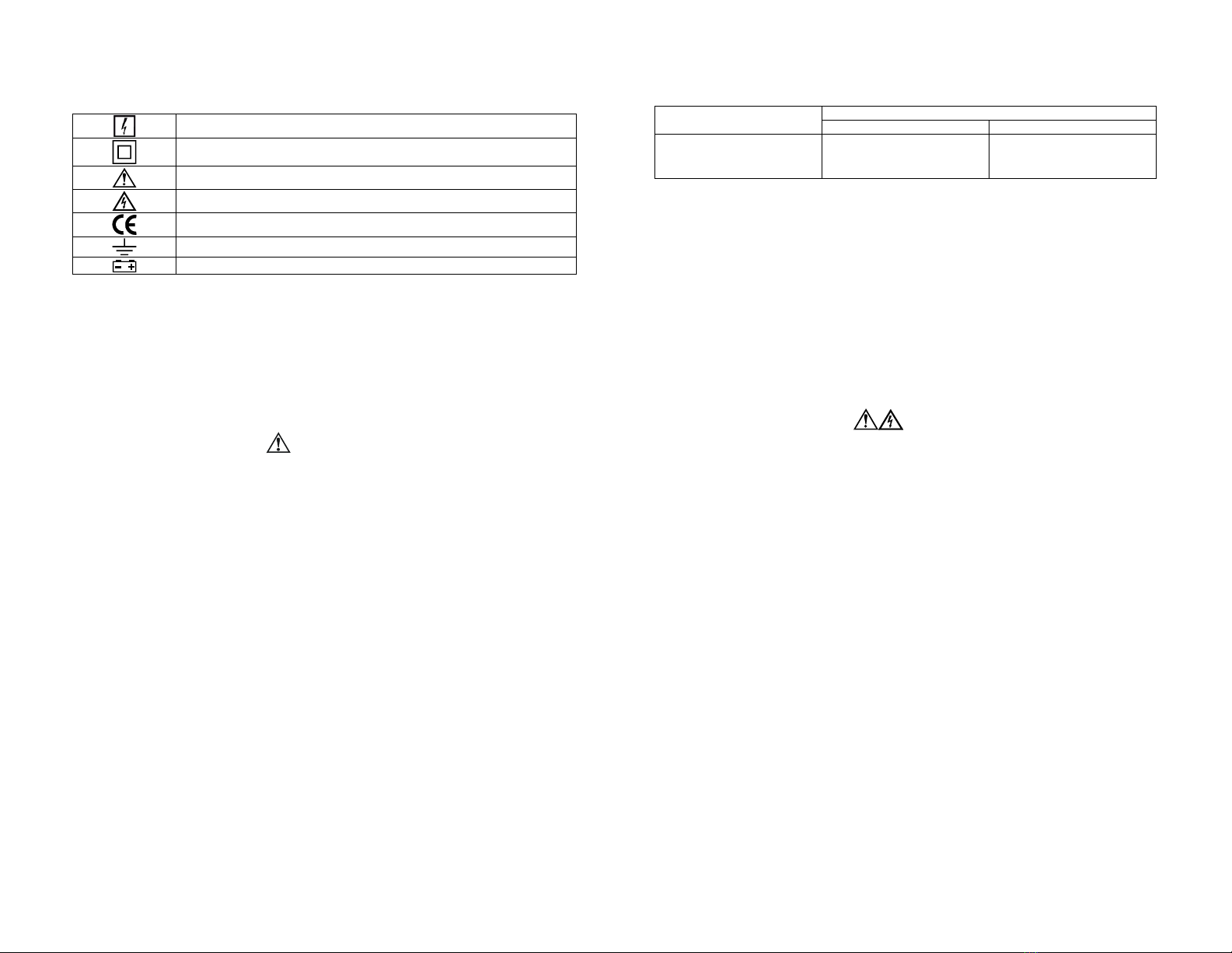
manuals.online logo
Brands
  1. Home
  2. •
  3. Brands
  4. •
  5. Fluke
  6. •
  7. Measuring Instrument
  8. •
  9. Fluke 90i-610s User manual

Fluke 90i-610s User manual

Other Fluke Measuring Instrument manuals

Fluke 80PK-1 User manual

Fluke

Fluke 80PK-1 User manual

Fluke 85RF II User manual

Fluke

Fluke 85RF II User manual

Fluke 393 FC User manual

Fluke

Fluke 393 FC User manual

Fluke 323 User manual

Fluke

Fluke 323 User manual

Fluke Biomedical IDA-4 Plus Operators User manual

Fluke

Fluke Biomedical IDA-4 Plus Operators User manual

Fluke OptiView III Series User manual

Fluke

Fluke OptiView III Series User manual

Fluke 116 User manual

Fluke

Fluke 116 User manual

Fluke 80K-6 User manual

Fluke

Fluke 80K-6 User manual

Fluke 789 User manual

Fluke

Fluke 789 User manual

Fluke 317 User manual

Fluke

Fluke 317 User manual

Fluke i1010 User manual

Fluke

Fluke i1010 User manual

Fluke 1587 User manual

Fluke

Fluke 1587 User manual

Fluke RF303 Operators User manual

Fluke

Fluke RF303 Operators User manual

Fluke 360 User manual

Fluke

Fluke 360 User manual

Fluke 365 User manual

Fluke

Fluke 365 User manual

Fluke 374 FC User manual

Fluke

Fluke 374 FC User manual

Fluke DewK User manual

Fluke

Fluke DewK User manual

Fluke 393 User manual

Fluke

Fluke 393 User manual

Fluke 78 User manual

Fluke

Fluke 78 User manual

Fluke Micro-Bath 7102 User manual

Fluke

Fluke Micro-Bath 7102 User manual

Fluke IRR1-SOL User manual

Fluke

Fluke IRR1-SOL User manual

Fluke BT520 User manual

Fluke

Fluke BT520 User manual

Fluke 416D User manual

Fluke

Fluke 416D User manual

Fluke 301A User manual

Fluke

Fluke 301A User manual

Popular Measuring Instrument manuals by other brands

Powerfix Profi 278296 Operation and safety notes

Powerfix Profi

Powerfix Profi 278296 Operation and safety notes

Test Equipment Depot GVT-427B user manual

Test Equipment Depot

Test Equipment Depot GVT-427B user manual

Fieldpiece ACH Operator's manual

Fieldpiece

Fieldpiece ACH Operator's manual

FLYSURFER VIRON3 user manual

FLYSURFER

FLYSURFER VIRON3 user manual

GMW TG uni 1 operating manual

GMW

GMW TG uni 1 operating manual

Downeaster Wind & Weather Medallion Series instruction manual

Downeaster

Downeaster Wind & Weather Medallion Series instruction manual

Hanna Instruments HI96725C instruction manual

Hanna Instruments

Hanna Instruments HI96725C instruction manual

Nokeval KMR260 quick guide

Nokeval

Nokeval KMR260 quick guide

HOKUYO AUTOMATIC UBG-05LN instruction manual

HOKUYO AUTOMATIC

HOKUYO AUTOMATIC UBG-05LN instruction manual

Test Products International SP565 user manual

Test Products International

Test Products International SP565 user manual

General Sleep Zmachine Insight+ DT-200 Service manual

General Sleep

General Sleep Zmachine Insight+ DT-200 Service manual

Sensa Core Lacto Spark user manual

Sensa Core

Sensa Core Lacto Spark user manual

VOLTCRAFT UTS-1980 operating instructions

VOLTCRAFT

VOLTCRAFT UTS-1980 operating instructions

EBCHQ 94915 Operation manual

EBCHQ

EBCHQ 94915 Operation manual

Balluff BIP LD2-T017-01-EP-S4 Series user guide

Balluff

Balluff BIP LD2-T017-01-EP-S4 Series user guide

Pulsar IMP Lite Series instruction manual

Pulsar

Pulsar IMP Lite Series instruction manual

ETCR 6800 user manual

ETCR

ETCR 6800 user manual

IRIMO 984-6D-1 owner's manual

IRIMO

IRIMO 984-6D-1 owner's manual

manuals.online logo
manuals.online logoBrands
  • About & Mission
  • Contact us
  • Privacy Policy
  • Terms and Conditions

Copyright 2025 Manuals.Online. All Rights Reserved.

LIMITED WARRANTY & LIMITATION OF LIABILITY
This product will be free from defects in material and workmanship for one year from the date of
purchase. This warranty does not cover damage from accident, neglect, misuse or abnormal
conditions of operation or handling. Resellers are not authorized to extend any other warranty on
behalf of the supplier. To obtain service during the warranty period, send your defective product to
the nearest Fluke Authorized Service Center with a description of the problem.
THIS WARRANTY IS YOUR ONLY REMEDY. NO OTHER WARRANTIES, SUCH AS FITNESS
FOR A PARTICULAR PURPOSE, ARE EXPRESSED OR IMPLIED. THE SUPPLIER IS NOT
LIABLE FOR ANY SPECIAL, INDIRECT, INCIDENTAL OR CONSEQUENTIAL DAMAGES OR
LOSSES, ARISING FROM ANY CAUSE OR THEORY.
Since some states or countries do not allow the exclusion or limitation of an implied warranty or of
incidental or consequential damages, this limitation of liability may not apply to you.
Fluke Corporation,
P.O. Box 9090,
Everett WA 98206-9090, U.S.A.
Fluke Industrial B.V.,
P.O. Box 90,
7600 AB, Almelo, The Netherlands.
SERVICE CENTERS
To locate an authorized service center, visit Fluke on the World Wide Web: http://www.fluke.com
or call Fluke using any of the phone numbers listed below:
+1-888-993-5853 in U.S.A. and Canada
+31-40-2675200 in Europe
+1-425-446-5500 from other countries
Figure 1. Installing the battery. Figure 2. Measuring Setup.
90i-610s
AC/DC Current Probe
Instruction Sheet
INTRODUCTION
The 90i-610s is a clamp-on AC/DC Current Probe designed to measure current waveforms in
automotive applications with any Test Tool capable of millivolt measurements. There are two
measurement ranges: 0 to 100 A (output voltage 10 mV/A) and 0 to 600 A (output voltage 1 mV/A).
SAFETY INFORMATION
Read First: Safety Information
To ensure safe operation and service of the Current Probe, follow these
instructions:
•Read the operating instructions before use and follow all safety instructions.
•Use the Current Probe only as specified in the operating instructions; otherwise the
current probe’s safety features may not protect you.
•Check the magnetic mating surfaces of the probe jaws; these should be free of dust,
dirt, rust, and other foreign matter.
•Adhere to local and national safety codes. Individual protective equipment must be
used to prevent shock and arc blast injury where hazardous live conductors are
exposed.
•Do not hold the Current Probe anywhere beyond the tactile indicator, see Figure 2.
•Before each use, inspect the Current Probe. Look for cracks or missing portions of the
Current Probe housing or output cable insulation. Also look for loose or weakened
components. Pay particular attention to the insulation surrounding the jaws.
•Never use the Current Probe on a circuit with voltages higher than 600 V CAT II or 300
V CAT III.
−CAT II equipment is designed to protect against transients in circuits directly
connected to the low-voltage installation, such as household appliances, portable
tools and similar equipment.
−CAT III equipment is designed to protect against transients in equipment in fixed
equipment installations, such as distribution panels, feeders and short branch
circuits, and lighting systems in large buildings.
•Use extreme caution when working around bare conductors or bus bars. Contact with
the conductor could result in electric shock.
•Use caution when working with voltages above 60 V dc, 30 V ac rms or 42 V ac peak.
Such voltages pose a shock hazard.
•Keep cables away from rotating parts or belts.
Tactile indicator
March 2002 , rev 1, 10/05 GB
© 2002-2005 Fluke Corporation. All rights reserved.
Printed in The Netherlands.
All product names are trademarks of their respective
companies.
SYMBOLS
May be used on HAZARDOUS LIVE conductors.
Product is protected by double insulation.
Risk of Danger. Important information. See Users Manual.
Risk of Electric Shock.
Complies with relevant European standards.
Earth ground
Battery
UNPACKING
The following items should be included in the box of your Current Probe:
•AC/DC Current Probe 90i-610s
•Instruction sheet (This document)
•9V Battery, Type IEC 6LR61
•BNC-to-Banana Adapter PM9081/001
Check the contents of the shipping box for completeness. If something in the box has been
damaged or is missing, contact your distributor immediately.
INSTALLING THE BATTERY
WARNING
To avoid electrical shock, unclamp the Current Probe from any conductor, and
disconnect the Probe’s BNC connector from the Test Tool or any other
measurement tool before installing or replacing the battery.
Refer to Figure 1 and proceed as follows:
•Put the Current Probe in the OFF position.
•The battery cover is present in the bottom side of the Probe body. Loosen the screw in the
battery cover with a small crossheaded screwdriver.
•Slide the battery cover away from the Current Probe.
•Install the 9V battery (IEC 6LR61). Arrange the battery leads so that they will not be pinched
between Probe body and the battery cover.
•Reinstall the battery cover and secure the screw.
SPECIFICATIONS
All Electrical Specifications are valid at a temperature of 23
°
C
±
5
°
C (73
°
F
±
9
°
F).
Current Ranges: 0 to 100 A DC or AC peak, 0 to 600 A DC or AC peak.
Output Signals: 100 A range: 10 mV/A / 600 A range: 1 mV/A
Measurement Category Ratings:
300 V CAT III & 600 V CAT II, pollution degree 2 per EN 61010-1 & EN 61010-02-032.
Complies with American industry standards UL61010B-1 & UL61010B-2-032, and European
standards EN/IEC 61010-1 2nd Edition & EN/IEC 61010-02-032.
Accuracy:
Error (after zero check)
Input Current Error
(DC or AC peak) 10 mV/A 1 mV/A
0 to 100 A
100 to 400 A
400 to 600 A
±2 % of reading ±1 A
--
--
±3.5 % of reading ±3 A
±2.0 % of reading ±2 A
±3.0 % of reading ±2 A
Maximum Nondestructive Current: 800 A peak
Input Load Impedance (of host instrument): >1 MΩin parallel with up to 100 pF
Useful Bandwidth: DC and 40 to 400 Hz.
Dimensions: 73 x 215 x 27 mm (2.9 x 8.4 x 1.1 inches)
Weight: 400 g (14 oz.), battery included
Temperature: operating: 0 to 50 °C (32 to 122 °F), max humidity 75%; nonoperating: -20 to 60 °C
(-4 to 140 °F), max humidity 80%
Altitude: operating: 0 to 2000 meters (0 to 6500 feet); nonoperating: 0 to 12000 meters (0 to 40000
feet)
Temperature Coefficient:
0.2 * accuracy/ °C max. for temperature T<18 °C and T>28 °C (T<64 °F and T>82 °F)
Battery Life: With Alkaline IEC 6LR61, 60 hours typical, 40 hours minimum.
POWER AND DEMAGNETIZING
During normal operation the green ON-indicator flashes; the red LOW-indicator is on when battery
voltage is low.
WARNING
To avoid false readings which could cause injury, replace battery as soon as the
red Low Battery Indicator LED lights.
Auto power off automatically switches the Probe off after 30 minutes.
To Demagnetize the Probe, open and close the jaws several times.
CLEANING AND STORAGE
Periodically wipe the case with a damp cloth and detergent; do not use abrasives or solvents. Open
the jaws and wipe the magnetic pole pieces with a lightly oiled cloth. Do not allow rust or corrosion to
form on the magnetic core ends. Remove the battery if the Probe is not used for periods of longer
than 60 days.
MEASUREMENT INSTRUCTIONS
Refer to Figure 2 and proceed as follows:
•Connect the Current Probe to Input A or the volts and COM inputs of the Test Tool.
If necessary use the PM9081 adapter that is supplied with the Probe: for correct polarity, the
red leg of the adapter must be inserted into Input A or volts input and the black into COM.
•On the Current Probe: select range. Ensure that the green ON-indicator flashes; the red
LOW-indicator must be off.
•Adjust the Test Tool to current readout at a sensitivity of 10 mV/A or 1 mV/A and current AC +
DC measurement. For the proper settings see the user documentation of the Test Tool.
•Zero the Probe, especially after you have selected another measurement range.
•Clamp the Current Probe around the conductor. The + and – indications marked on the jaw of
the Probe must correspond with the orientation of the current to be measured. This assures a
correct reading of the current flow.
•Observe the current value and the shape of the waveform on the display of the Test Tool.
Mouser Electronics
Authorized Distributor
Click to View Pricing, Inventory, Delivery & Lifecycle Information:
Fluke:
90I-610S