manuals.online logo
Brands
  1. Home
  2. •
  3. Brands
  4. •
  5. Fluke
  6. •
  7. Multimeter
  8. •
  9. Fluke 8010A User manual

Fluke 8010A User manual

Other manuals for 8010A

3

This manual suits for next models

1

Other Fluke Multimeter manuals

Fluke 45 User manual

Fluke

Fluke 45 User manual

Fluke 110 User manual

Fluke

Fluke 110 User manual

Fluke 80 Series V Use and care manual

Fluke

Fluke 80 Series V Use and care manual

Fluke 79 III Use and care manual

Fluke

Fluke 79 III Use and care manual

Fluke 28 II Ex Use and care manual

Fluke

Fluke 28 II Ex Use and care manual

Fluke 110 Use and care manual

Fluke

Fluke 110 Use and care manual
Fluke 27 User manual

Fluke

Fluke 27 User manual

Fluke 77 User manual

Fluke

Fluke 77 User manual

Fluke 1587 User manual

Fluke

Fluke 1587 User manual

Fluke 1508 User manual

Fluke

Fluke 1508 User manual

Fluke 789 Original instructions

Fluke

Fluke 789 Original instructions

Fluke CNX 3000 User manual

Fluke

Fluke CNX 3000 User manual

Fluke 76 User manual

Fluke

Fluke 76 User manual

Fluke 8840A User manual

Fluke

Fluke 8840A User manual

Fluke 8060A User manual

Fluke

Fluke 8060A User manual

Fluke 8010A User manual

Fluke

Fluke 8010A User manual

Fluke 1587 FC User manual

Fluke

Fluke 1587 FC User manual

Fluke 233 User manual

Fluke

Fluke 233 User manual

Fluke 77 Use and care manual

Fluke

Fluke 77 Use and care manual

Fluke 1630 Instruction manual

Fluke

Fluke 1630 Instruction manual

Fluke 8024B User manual

Fluke

Fluke 8024B User manual

Fluke 15B Use and care manual

Fluke

Fluke 15B Use and care manual

Fluke 77 User manual

Fluke

Fluke 77 User manual

Fluke 8060A User manual

Fluke

Fluke 8060A User manual

Popular Multimeter manuals by other brands

VAR DV-71600 manual

VAR

VAR DV-71600 manual

Agilent Technologies 34420A user guide

Agilent Technologies

Agilent Technologies 34420A user guide

Hameg HM 8012 manual

Hameg

Hameg HM 8012 manual

Mastech MY70 Operation manual

Mastech

Mastech MY70 Operation manual

Steren MUL-300 user manual

Steren

Steren MUL-300 user manual

Somogyi Elektronic home SMA 92 instruction manual

Somogyi Elektronic

Somogyi Elektronic home SMA 92 instruction manual

Gossen MetraWatt METRAmax 6 operating instructions

Gossen MetraWatt

Gossen MetraWatt METRAmax 6 operating instructions

PeakTech 4000 Procedure of calibration

PeakTech

PeakTech 4000 Procedure of calibration

YOKOGAWA 90050B user manual

YOKOGAWA

YOKOGAWA 90050B user manual

Tempo Communications MM200 instruction manual

Tempo Communications

Tempo Communications MM200 instruction manual

APPA 607 user manual

APPA

APPA 607 user manual

Elenco Electronics CM-1555 operating instructions

Elenco Electronics

Elenco Electronics CM-1555 operating instructions

Mastech MS8238C user manual

Mastech

Mastech MS8238C user manual
SDAR 830A, 830B, 830D, 830C user manual

SDAR

SDAR 830A, 830B, 830D, 830C user manual

RS PRO RS-9519BT instruction manual

RS PRO

RS PRO RS-9519BT instruction manual

BGS technic 8890 instruction manual

BGS technic

BGS technic 8890 instruction manual

Amprobe Hexagon 60 user manual

Amprobe

Amprobe Hexagon 60 user manual

Morris 57074 user manual

Morris

Morris 57074 user manual

manuals.online logo
manuals.online logoBrands
  • About & Mission
  • Contact us
  • Privacy Policy
  • Terms and Conditions

Copyright 2025 Manuals.Online. All Rights Reserved.

:
|
8010A/8012A
P/N
491944
August
1978
Rev
2
1/85
@
1985,
John
Fluke
Mfg.
Co,,
Inc.
All
rights
reserved.
Litho
In
U.S.A.
Digital
Multimeters
Instruction
Manual
—
LF
ters
ime:
ital
Multi
igi
8010A/8012A
Di
vi
Section
1
Introduction
and
Specifications
1-1.
INTRODUCTION
1-2.
This
manual
contains
complete
operating
and
maintenance
instructions
for
the
Fluke
Models
8010A
and
8012A
Digital
Multimeters.
The
information
presented
in
this
manual
reflects
both
instruments
except
where
indicated
by
a
particular
model
number.
The
term
Multimeter
is
used
throughout
this
manual
to
indicate
both
the
8010A
and
the
8012A.
1-3.
The
Multimeters
are
portable
bench-type
digital
multimeters
(DMMs)
with
3-1/2
digit
liquid
crystal
displays
(LCDs).
The
Multimeters
have
the
following
industry-standard
features:
e
Voltage
measurements
from
100
pV
to
1000V
dc
and
10
mV
to
750V
true-rms
ac.
e
Current
measurements
from
100
nA
to
2A
deand
10
HA
to
2A
true-rms
ac
(up
to
10A
for
the
8012A).
e
Resistance
measurements
from
100
mN
(1
mQ
for
the
8012A)
to
20
MQ.
The
Multimeters
also
have
the
following
special
measurement
features:
e
Conductance
measurements
up
to
10,000
MQ
of
equivalent
resistance.
e
Resistance
ranges
that
supply
enough
voltage
to
turn
on
a
PN
junction
for
testing
diodes
and
transistors.
@
Automatic
polarity
indication
and
overrange
indication.
°
Protection
from
overloads
and
transients
up
to6
kV
for
10
microseconds.
©
Dual-slope
integration
a/d
conversion
to
ensure
noise-free
measurements.
e
Long
term
calibration
stability
(1
year).
14.
Your
Multimeter
is
warranted
for
a
period
of
one
year
upon
shipment
of
the
instrument
to
the
original
purchaser.
Conditions
of
the
warranty
are
given
at
the
front
of
this
manual.
1-5.
OPTIONS
and
ACCESSORIES
14.
The
use
of
your
Multimeter
can
be
enhanced
by
the
options
and
accessories
available
for
these
instruments.
The
options
and
accessories
are
listed
in
Table
1-1.
The
Multimeters
can
be
ordered
with
the
Option
8010A-01
or
8012A-01
Rechargeable
Battery.
Detailed
information
on
options
and
accessories
is
contained
in
Section
6
of
this
manual,
1-7.
SPECIFICATIONS
1-8.
Specifications
for
the
Multimeters
are
listed
in
Table
1-2.
Specifications
for
the
Option
8010A-01
or
Option
8012A-01
and
other
accessory
specifications
are
given
in
Section
6
of
this
manual.
INTRODUCTION
AND
SPECIFICATIONS
SPECIFICATIONS
Table
1-1.
8010A/8012A
Options
and
Accessories
INPUT
IMPEDANCE
MODEL
DESCRIPTION
MODEL
DESCRIPTION
C86
Ruggedized
Carrying
Case
80J-10
Current
Shunt
Y8205
Soft
Carrying
Case
80K-6
High
Voltage
Probe
M00-200-611
Offset
Mounting
Kit
80K-40
High
Voltage
Probe
M00-200-612
Center
Mounting
Kit
83-RF
RF
Probe
MO0-200-613
Dual
Mounting
Kit
85-RFE
RE
Probe
80T-H
Touch-Hold
Probe
Y8100
DC/AC
Current
Probe
80T-150C
Temperature
Probe,
Celsius
Y8101
AC
Current
Transformer
80T-150F
Temperature
Probe,
Fahrenheit
Y8133
Deluxe
Test
Lead
Set
80i-400
AC
Current
Probe
Y8140
Slim-Flex
Test
Leads
80i-600
AC
Current
Probe
8010A-01
Rechargeable
Battery
Option
for
8010A
8012A-01
Rechargeable
Battery
Option
for
8012A
Table
1-2.
8010A/8012A
Specifications
ELECTRICAL.
ss 2s
esis
iia
See
S55
swe
eats
The
electrical
specifications
given
apply
for
an
operating
temperature
of
18°C
to
28°C
(64.4°F
to
82.4°F),
relative
humidity
up
to
90%,
and
a
1-year
calibration
cycle.
Functions
.......:eccescesceveeetecetececn
DC
Volts,
AC
Volts,
DC
Current,
AC
Current
Resistance
and
Conductance.
DC
Volts
[
RANGE
RESOLUTION
ACCURACY
for
1-Year
£200
mV
100
uV
+2V
1mvV
+20V
10
mV
£(0.1%
of
reading
+
1
digit)
+200V
100
mV
+1000V
1V
NORMAL
MODE
REJECTION
RATIO
10
MQ,
all
ranges.
>90
dB
at
de,
50
Hz
and
60
Hz.
.
>60
dB
at
60
Hz
(at
50
Hz
with
50
Hz
Option).
COMMON
MODE
REJECTION
RATIO
....
(1
kQ
unbalanced)
AC
Volts
(True
RMS
Responding)
OVERVOLTAGE
PROTECTION
....
RESPONSE
TIME
.......-..ecse
eee
se
iaastidee
1
second.
10Q00V
dc
or
peak
ac
on
all
ranges.
ACCURACY
for
1-Year
(5%
of
Range
to
Full
Range)
RANGE
RESOLUTION
45
Hz
10
kHz
20
kHz
:
to
1
kHz
to
10
kHz
|
to
20
kHz
to
50
kHz
200
mV
100
nV
+
(5%of
2vV
1
mV
+.(1,0%
of
reading
+
3
20V
10
mV
+(0.5%
of
reading
+
2
digits}/
reading
+
2
digits)
LL
200V
O.1V
t
digits)
+
(0.5%
of
FE
Se
750V
WV
reading
+
2
|
digits)
L
INTRODUCTION
AND
SPECIFICATIONS
SPECIFICATIONS
Table
1-2.
8010A/8012A
Specifications
(cont)
AC
Volts,
continued
VOLT-Hz
PRODUCT
oe
eee
eee
eee
eee
107
max
(200V
max
@
50
kHz).
EXTENDED
FREQUENCY
RESPONSE
...
Typically
+3 dB
at
200
kHz.
COMMON
MODE
NOISE
REJECTION
RATIO
(1
kQ
unbalance)
...............0,
>60
dB
at
50
Hz
and
60
Hz.
CREST
FACTOR
RANGE
.............055
1.0
to
3.0.
INPUT
IMPEDANCE
.........c..cesee
eee
10
MQ
in
parailel
with
<100
pF.
OVERLOAD
PROTECTION
750V
rms
or
1000V
peak
continuous
not
to
exceed
the
volt-hertz
product
of
10’
(except
10
seconds
maximum
on
200
mV,
2V
ranges).
RESPONSE
TIME...
eee
cece
eee
e
eee
2
seconds
maximum
within
a
range.
DC
Current
RESOLUTION
ACCURACY
for'1-Year
BURDEN
VOLTAGE
+(0.3%
of
reading
+1
digit)
0.3V
max.
0.9V
max.
OVERLOAD
PROTECTION
...........065
2A/250V
fuse
in
series
with
3A/600V
fuse
(for
high
energy
sources).
AC
Current
(True
RMS
Responding
AC
Coupled)
—
=
ACCURACY:
from
5%
of
range
to
full-scale,
1-Year
“
BURDEN
E
RESOLUTION
BANG
Orr
VOLTAGE
200
pA
0.1
pA
t
2mA
1
uA
‘
.
2
£(1%
of
reading
+2
digits)
#(2%
of
reading
0.3V
rms
max.
20
mA
10
uA
;
+2
digits)
200
mA
100
pA
2000
mA
1mA
£(1%
of
reading
'
0.9V
rms
max.
+2
digits}
OVERLOAD
PROTECTION
..............
2A/250V
fuse
in
series
with
3A/600V
fuse
(for
high
energy
sources).
:
CREST
FACTOR
RANGE
........-...0005
1.0
to
3.0
High
Current
8010A
Only
ACCURACY:
for
1-Year
BURDEN
VOLTAGE
10A
de
+(0.5%
of
reading
+
1
digit)
0.5V
max.
10A
45
Hz
to
2
kHz
Trms
ac
One
+(1%
of
reading
+
2
digits}
DSON
EMS
CaN:
OVERLOAD
5.
posse
a8
5h
deca
ec
lnjo
bin
gueonns
ttewe
deat
12A
maximum
unfused.
1-3
INTRODUCTION
AND
SPECIFICATIONS
SPECIFICATIONS
Table
1-2.
8010A/8012A
Specifications
(cont)
1-4
aa
a
re
Resistance
FULL-SCALE
MAXIMUM
TEST
!
:
‘
RESOLUTION
ACCURACY:
for
1-Year
VOLTAGE
CURRENT
2kQ
wt
12
+(0.2%
of
reading
>
1.0V
1.3mA
+1
digit)
<0.25V
10
pA
200
kKQ
~ph
>
1.0V
35
uA
2000
kQ
+(0.5%
of
reading
<0.25V
0.10
A
+1
digit)
0.35
uA
OVERLOAD
PROTECTION
..............
300V
dc/ac
rms
on
all
ranges.
OPEN
CIRCUIT
VOLTAGE
...............
Less
than 3.5V
on
all
ranges.
RESPONSE
TIME
2.2...
ccc
eee
eee
eee
1
second
all
ranges
except
4
seconds
on
the
2000
kQ
and
20
MQ
ranges.
DIODE
TEST
-cicii
sie
sie’
su
iwitle
ate
ktnnes
These
three
ranges
have
enough
voltage
to
turn
on
silicon
>
junctions
to
check
for
proper
forward-to-back
resistance.
The
2
kQ
range
is
preferred
and
is
marked
with
a
larger
diode
symbol
on
the
front
panel
of
the
instrument.
The
three
non-diode
test
ranges
will
not
turn
on
silicon
junctions
so
in-circuit
resistance
measurements
can
be
made
with
these
three
ranges.
Low
Resistance
8012A
Only
FULL-SCALE
MAXIMUM
RANGE
RESOLUTION
|
ACCURACY:
for
1-Year
VOLTAGE
TEST
CURRENT
£(1%
of
reading
+2
digits)
ie
pee
202
(LO
Ohms}
+(0.5%
of
reading
+2
digits)
OVERLOAD
PROTECTION
..........-...
300V
de/ac
rms
on
ail
ranges.
RESPONSE
TIME...
«0...
ese
e
eee
eee
eee
1
second
maximum.
OPEN
CIRCUIT
VOLTAGE
............055
16V
maximum
on
both
ranges.
Conductance
OPEN
MAXIMUM
RESOLUTION
|
ACCURACY:
for
1-Year
CIRCUIT TEST
VOLTAGE
CURRENT
+(0.2%
of
reading
20
uS
10
nS
+
1
digit)
+(1%
of
reading
.
|
200
nS
i,
.1nS
Zz
+10
digits}
<1V
0.10
uA
OVERLOAD
PROTECTION
............4.
300V
dce/ac
rms
on
ail
ranges.
,
CONDUCTANCE
UNITS
........--
eevee
We
use
the
international
unit
of
conductance,
the
Siemen
=
S
=
1/Q.
Another
unit
of
conductance
is
the
mho.
Table
1-2
ENVIRONMENTAL
Temperature
Coefficient
Operating
Temperature
RELATIVE
HUMIDITY
Storage
Temperature
RELATIVE
HUMIDITY
GENERAL
Maximum
Common
Mode
Voltage
Power
Requirements
Weight
LINE
MODEL
.....
cece
eee
e
eens
BATTERY
MODEL
INTRODUCTION
AND
SPECIFICATIONS
;
SPECIFICATIONS
.
8010A/8012A
Specifications
(cont)
<0.1
times
the
applicable
accuracy
specification
per
°C
for
0°C
to
18°C
and
28°C
to
50°C
(32°F
to
64.4°F
and
50.4°F
to
122°F).
O°C
to
50°C
(32°F
to
122°F).
Oto
80%,
0°C
to
35°C
(32
to
95°F)
on
2000
kQ,
20
MQ
and
200
nS
ranges.
O
to
80%,
0°C
to
35°C
(32
to
95°F)
on
all
other
ranges.
0
to
70%,
35°C
to
50°C
(95
to
122°F).
(without
batteries):
-40°C
to
+60°C
(-40°F
to
+158°F)
(with
batteries):
-40°C
to
+50°C
(-40°F
to
+122°F)
0
to
90%,
-40
to
50°C
{-40
to
+122°F)
0
to
90%,
50
to
60°C
(122
to
140°F).
500V
de
or
peak
ac.
90
to
132V
or
200
to
264V
at
50
Hz
or
60
Hz.
Line
Model
2W.
(Battery
Model
3.5°W.)
(See
Figure
1-1.)
1.08
kg
(2
Ib
6
oz)
1.42
kg
(3
Ib,
6
0z)
8.55
in.
(21,72
cm)
ome
in.
(19,05
=
9.65
in.
(27,05
cm)
9.90
in.
(25,15
—
—
2.52
in.
(6,40
cm)
Figure
1-1.
8010A/8012A
Dimensions
1-5/1-6
dg
2-1.
INTRODUCTION
2-2.
This
section
describes
how
to
set
up
and
make
measurements
with
your
Multimeter.
Even
though
you
may
have used
a
multimeter
before,
we
recommend
that
you
read
the
entire
section
carefully
so
that
youcan
use
all
of
the
features
of
your
Multimeter.
2-3.
SETTING
UP
YOUR
INSTRUMENT
2-4.
Unpacking
2-5.
Your
Multimeter
is
shipped
in
a
special
protective
container
that
should
prevent
damage
to
the
instrument
during
shipping.
Check
the
shipping
order
against
the
contents
of
the
container
and
report
any
damage
or
short
shipment
to
the
place
of
purchase
or
the
nearest
Fluke
Technical
Service Center.
A
list
of
these
service
centers
is
located
in
Section
5.
The
container
should
include
the
following:
@
The
8010A
or
8012A
Multimeter
@
Two
test
leads
(one
red
and
one
black)
e
Line
power
cord
e@
The
8010A/8012A
Instruction
Manual
2-4.
Ifreshipment
of
the
instrument
is
necessary,
please
use
the
original
shipping
container.
If
the
original
container
is
not
available,
be
sure
that
adequate
protection
is
provided
to
prevent
damage
during
shipment.
We
recommend
that
the
instrument
be
surrounded
by
at
least
three
inches
of
shock-absorbing
material
on
all
sides
of
the
container.
2-7.
Remove
the
Multimeter
from
its
container
and
place
it
in
a
convenient
location.
The
carrying
handle
on
the
meter
can
be
used
as
a
prop-stand
or
positioned
out
of
the
way
(behind
the
Multimeter).
To
position
the
handle,
pull
outward
on
the
hubs
of
the
handle
and
rotate
the
handle
into
position.
Section
2
Operation
2-8.
AC
Line
Voltage
Requirements
2-9.
AC
line
voltage
requirements
for
your
Multimeter
are
listed
on
a
decal
attached
to
the
bottom
of
the
instrument.
Refer
to
Section
4
for
the
procedure
to
change
the
ac
line
voltage
setting.
If
your
Multimeter
has
the -01
Battery
Option,
refer
to
Section
6
for
information
on
changing
ac
line
voltages.
CAUTION
Bo
not
connect
the
power
cable
to
the
instrument
before
verifying
that
the
intended
source
matches
the
ac
line
configuration
of
the
instrument.
2-10.
Fuse
Replacement
2-11.
There
is
one,
user-replaceable
fuse
(F1)
in
your
Multimeter.
The
fuse
(Fl)
and
the
fuse
holder
form
an
integral
part
of
the
mA
input
connector
and
can
be
removed
with
ordinary
tools.
The
fuse
rating
is:
2A,
normal
blow
(recommended
part
AGX2).
2-12.
Use
the
following
procedure
to
replace
the
fuse,
Fl:
1.
Set
the
POWER
switch
to
OFF.
°
2.
Remove
the
input
power
cord
from
the
Multimeter.
WARNING
DO
NOT
REPLACE
THE
FUSE WITH
THE
INSTRUMENT
TURNED
ON OR
CONNECT-
ED
TO
LINE
POWER.
3.
Refer
to
Figure
2-1,
item
5
for
the
location
of
the
fuse
holder.
2-4
OPERATION
FRONT
PANEL
FEATURES
SE
OO
wm
4,
Using
a
coin
or
wide
blade
screwdriver,
push
in
while
turning
the
fuse
holder
in
the
direction
of
the
arrow
on
the
front
panel
decal.
5.
Pull
out
the
fuse
holder
and
replace
the
defective
fuse.
2-13.
FRONT
PANEL
FEATURES
2-14.
Before
using
your
Multimeter,
take
a
few
minutes
to
become
familiar
with
the
use
ofits
controls,
indicators,
and
connectors.
The
front
panel
features
are
shown
in
Figure
2-1
and
described
in
Table
2-1.
The
features
of
the
Liquid
Crystal
Display
(LCD)
are
also
described
in
the
following
paragraphs,
2-15.
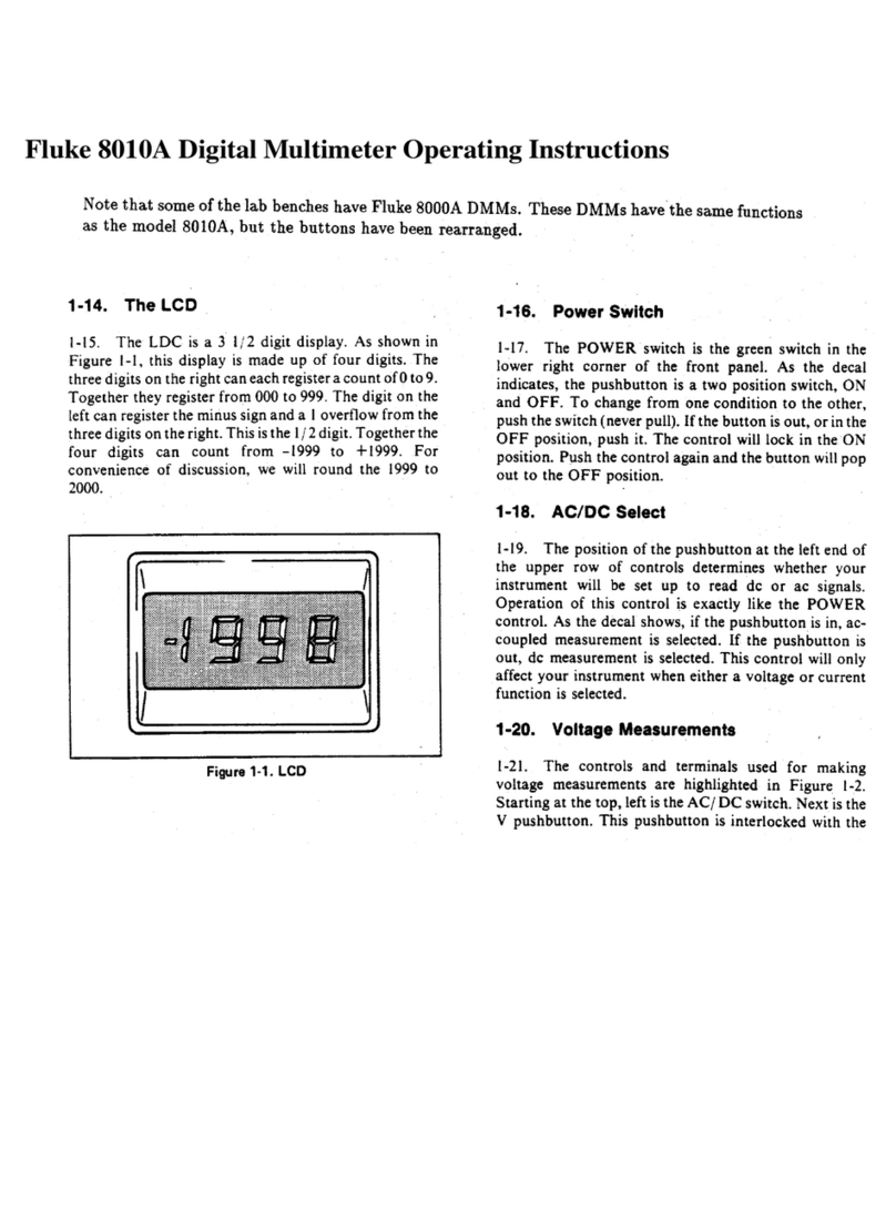
LCD
DISPLAY
2-16.
The
features
of
the
Liquid
Crystal
Display
(LCD)
are
shown
in
detail
in
Figure
2-2.
The
position
of
the
floating
decimal
point
is
determined
by
the
range
selected.
The
maximum
measurement
value
that
can
be
displayed
is
one
count
less
than
the
range
selected
(e.g.,
maximum
—
measured
voltage
that
can
be
displayed
in
the
200
mV
range
would
be
199.9
mV).
2-17.
To
extend
the
life
of
the
LCD
and
to
ensure
that
the
display
will
be
ready
to
operate,
observe
the
following
precautions:
e
Do
not
store
or
use
the
instrument
in
temperatures
above
or
below
those
specified
in
Section
1.
e
Do
not
store
or
use
the
instrument
in
humidity
above
that
specified
in
Section
1.
NOTE
Low
temperatures
(within
the
specified
operating
limits)
will
cause
the
LCD
response
to
be
sluggish.
e
Avoid
prolonged
exposure
of
the
LCD
to
direct
sunlight
(ultraviolet).
750y
AC
}
200
mv¥
2
COC
}QM
vA
2)
O78)
(BaP
ee
"20
2
=
POM}
EI
Ee)
Ee)
sea)
Gee
Ems ae)
(ae
20
Soe)
Ca
2000S
mm)
Figure
2-1.
Controls,
Indicators,
and
Connectors
OPERATION
FRONT
PANEL
FEATURES
Table
2-1.
8010A/8012A
Controls,
Indicators,
and
Connectors
ITEM
NO.
NAME
FUNCTION
1
Display
2
AC/DC
Function
Switch
3
V/mA/kQ/S
Function
Switches
4
Range
Switches
5
mA
Input
Connector
6
COMMON
Input
Connector
7
V/KQ/S
Input
Connector
8
10A
Input
Connector
9
Low
Ohms
Input
Connector
/ZERO
Controi
10
POWER
Switch
3%-digit
LCD
display.
Indicates
measured
input
values
and
an
overrange
condition.
(Also
contains
an
annunciator
for
low
battery
charge,
if
the
Rechargeable
Battery
Option
is
installed.)
A
two-position
switch
(push
IN
and
push
OUT)
used
to
select
ac
(IN)
or
dc
(OUT)
for
current
or
voltage
measurement.
Interlocked
switches,
used
with
the
AC/DC
Function
switch
to
select
the
measurement
functions.
Pushing
one
switch
will
release
the
others.
The
conductance
function
is
selected
by
pushing
the
kQ
switch
and
one
of
three
pairs
of
Range
Function
switches.
The
Low
Ohms
feature
of
the
8012A
is
selected
by
pressing
the
V
and
mA
switches
simultaneously.
Interlocked
switches
that
select
the
measurement
ranges.
Pushing
a
switch
selects
the
corresponding
range
and
releases
a
depressed
switch(es).
A
fuse
protected,
test
lead
connector
for
current
measurements,
less
than
2A.
Fuse
is
accessible
from
the
front
panei.
Test
lead
connector
used
as
the
low
or
common
input
for
all
measurement
functions.
Test
lead
connector
used
as
the
high
input
for
ail
voltage,
resist-
ance,
continuity
and
conductance
measurement
functions.
Test
lead
connector
used
for
the
10A
Range
current
function
of
the
8010A.
Test
lead
connector
used
for
the
Low
Ohms
resistance
function
of
the
8012A.
ZERO
Control
used
to
compensate
for
test
lead
resistance.
Push-on/push-off
switch.
Used
for
energizing
and
de-energiz-
ing
the
instrument.
LOW
BATTERY
INDICATOR
(RECHARGEABLE
BATTERY
OPTION
ONLY)
POLARITY
SIGN
DISABLED
ae
agi
|
|
DURING
Vac,
mA/Aac,
and
KQ
FUNCTIONS
DISPLAY
ANNUNCIATORS
OVERRANGE
INDICATION
Position
of
decimal
point
dependent
on
range
selected.
NOTE:
Figure
2-2.
Liquid
Crystal
Display
2-3