manuals.online logo
Brands
  1. Home
  2. •
  3. Brands
  4. •
  5. Fluke
  6. •
  7. Multimeter
  8. •
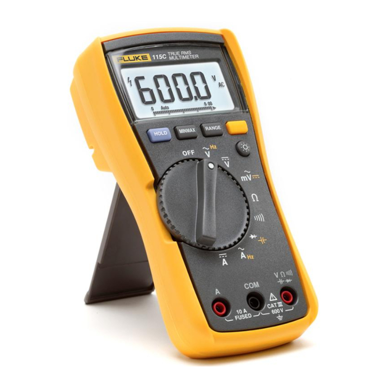
  9. Fluke 8024B User manual

Fluke 8024B User manual

Other manuals for 8024B

2

Other Fluke Multimeter manuals

Fluke 8845A User manual

Fluke

Fluke 8845A User manual

Fluke 279 FC User manual

Fluke

Fluke 279 FC User manual

Fluke 27 User manual

Fluke

Fluke 27 User manual

Fluke 287 Installation and operating instructions

Fluke

Fluke 287 Installation and operating instructions

Fluke 8600A User manual

Fluke

Fluke 8600A User manual

Fluke Ti30 User manual

Fluke

Fluke Ti30 User manual

Fluke 8845A Use and care manual

Fluke

Fluke 8845A Use and care manual

Fluke 27-II User manual

Fluke

Fluke 27-II User manual

Fluke 233 Use and care manual

Fluke

Fluke 233 Use and care manual

Fluke 80 Series III Operating and installation instructions

Fluke

Fluke 80 Series III Operating and installation instructions

Fluke 179 User manual

Fluke

Fluke 179 User manual

Fluke 8808A User manual

Fluke

Fluke 8808A User manual

Fluke FL8808A User manual

Fluke

Fluke FL8808A User manual

Fluke 83V User manual

Fluke

Fluke 83V User manual

Fluke 1587 Use and care manual

Fluke

Fluke 1587 Use and care manual

Fluke 8845A User manual

Fluke

Fluke 8845A User manual

Fluke 116 User manual

Fluke

Fluke 116 User manual

Fluke CNX i3000 Use and care manual

Fluke

Fluke CNX i3000 Use and care manual

Fluke 789 User manual

Fluke

Fluke 789 User manual

Fluke 15B MAX Use and care manual

Fluke

Fluke 15B MAX Use and care manual

Fluke 805 User manual

Fluke

Fluke 805 User manual

Fluke 88 V User manual

Fluke

Fluke 88 V User manual

Fluke 80 Series V User manual

Fluke

Fluke 80 Series V User manual

Fluke III Series User manual

Fluke

Fluke III Series User manual

Popular Multimeter manuals by other brands

VAR DV-71600 manual

VAR

VAR DV-71600 manual

Agilent Technologies 34420A user guide

Agilent Technologies

Agilent Technologies 34420A user guide

Hameg HM 8012 manual

Hameg

Hameg HM 8012 manual

Mastech MY70 Operation manual

Mastech

Mastech MY70 Operation manual

Steren MUL-300 user manual

Steren

Steren MUL-300 user manual

Somogyi Elektronic home SMA 92 instruction manual

Somogyi Elektronic

Somogyi Elektronic home SMA 92 instruction manual

Gossen MetraWatt METRAmax 6 operating instructions

Gossen MetraWatt

Gossen MetraWatt METRAmax 6 operating instructions

PeakTech 4000 Procedure of calibration

PeakTech

PeakTech 4000 Procedure of calibration

YOKOGAWA 90050B user manual

YOKOGAWA

YOKOGAWA 90050B user manual

Tempo Communications MM200 instruction manual

Tempo Communications

Tempo Communications MM200 instruction manual

APPA 607 user manual

APPA

APPA 607 user manual

Elenco Electronics CM-1555 operating instructions

Elenco Electronics

Elenco Electronics CM-1555 operating instructions

Mastech MS8238C user manual

Mastech

Mastech MS8238C user manual

SDAR 830A, 830B, 830D, 830C user manual

SDAR

SDAR 830A, 830B, 830D, 830C user manual

RS PRO RS-9519BT instruction manual

RS PRO

RS PRO RS-9519BT instruction manual

BGS technic 8890 instruction manual

BGS technic

BGS technic 8890 instruction manual

Amprobe Hexagon 60 user manual

Amprobe

Amprobe Hexagon 60 user manual

Morris 57074 user manual

Morris

Morris 57074 user manual

manuals.online logo
manuals.online logoBrands
  • About & Mission
  • Contact us
  • Privacy Policy
  • Terms and Conditions

Copyright 2025 Manuals.Online. All Rights Reserved.

NOTE
This
manual
documents
the
Model
8024B
and
its
assemblies
at
the
revision
levels
-
ghown
in
Appendix
A.
If
your
instrument
contains
assemblies
with
different
revision
letters,
it
will
be
necessary
for
you
to
either
update
or
backdate
this
manual.
Refer
to
the
supplemental
change/errata
sheet
for
newer
assemblies,
or
the
backdating
sheet
in
Appendix
A
for
older
assemblies.
8024B
Digital
Multimeter
Instruction
Manual
P/N
616052
July
1981
FLUKE
©1981,
John
Fluke
Mfg.
Co.,
Inc.,
all
rights
reserved
Litho
in
U.S.A.
Dear
Customer:
Congratulations!
We
at
Fluke
are
proud
to
present
you
with
the
Model
8024B
Multimeter.
This
instrument
represents
the
very
latest
in
integrated
circuit
and
display
technology.
As
a
result,
the
end
product
is
a
rugged
and
reliable
instrument
whose
performance
and
design
exhibit
the
qualities
of
a
finely
engineered
lab
instrument.
To
fully
appreciate
and
protect
your
investment,
we
suggest
you
take
a
few
moments
to
read
the
manual.
As
always,
Fluke
stands
behind
your
8024B
witha
full
2-year
warranty
and
a
worldwide
service
organization.
If
the
need
arises,
please
don’t
hesitate
to
call
on
us.
Thank
you
for
your
trust
and
confidence.
Fohn
Fluke
Mfg.
Co.,
Inc.
SECTION
1
8024B
Table
of
Contents
TITLE
PAGE
INTRODUCTION
AND
SPECIFICATIONS
.......--------
1-1
I-].
INTRODUCTION
....----eeeeeee
ere
er
rtersrese
1-1
1-3.
SPECIFICATIONS
....-cceeeeereeer
seer
errrtces
1-1
OPERATING
INSTRUCTIONS
.......-----sser
rrr
2-1
9-1.
INTRODUCTION
.....--eeeeeere
reer
ester
terete
2-4
2-3.
PREPARING
FOR
OPERATION
....--ee
eee
ee
teee
2-1
2-4.
Linpacking
ustiics
stor
ta
ee
etenen
eter
en
st
2-1
2-7.
Battery
or
Fuse
Installation/
Replacement
....----+-->
2-1
9-9,
PHYSICAL
FEATURES.....-.:+seserererrrrrcees
2-3
9-11,
OPERATING
NOTES
....-.--eeerererrs
er
serccses
2-6
2-13.
Input
Overload
Protection
....-++++e+rerrrrrrttte
2-6
2-15.
Input
Connection
to
COMMON
.....--e
ee
errr
2-6
2-17.
Fuse
Cheek.
ov
ccuce
wackans
seen cass
Spies
nice
as
cies
2-7
2-19,
Fuse
Replacement
....-.+-+eesereersrrtressests
2-7
2-21.
The
Displayenciqcra
ve
vane
sits
hatee
det
ete
tee
2-8
596
OPERATION
cas
u
cists
se
ee
cesarean
enti
e
ee
sere
se
2-9
2-28.
AC/DC
Volts
(V)
Operation
...-+e
eee
ee
reece
eres
2-9
2-30.
AC/DC
Current
(mA)
Operation
.....--ee
eer
eeeeee
2-9
2-32.
Resistance
({(2)
Operation.
....--.eeeeeeeereertes
2-9
2-34.
Continuity
Testing
........-+eee
reece
er
eres
rst
2-13
2-36.
Diode:
Testing
cvs
Sacneven
tans
oo
tose
erent
ee
2-13
2-38.
Conductance
(S)
Operation
....-+-seeee
reer
reste
2-13
2-40.
Temperature
(°C)
Operation
«0...
essere
ee
eee
eee
2-13
2-43.
Level
Detector
Operation
....-----
errs
eee
crerees
2-16
2-45.
Peak
Hold
Operation
....---.e+eeeereeeerterteess
2-17
9-47.
INITIAL
CHECK-OUT
PROCEDURE
......---++-++:
2-19
2-49.
MEASUREMENT
TECHNIQUES
.....--.-
eee
reer
2-21
2-54.
Temperature
Conversion.
...+-+++eerrrrrrerrrtertt
2-21
2-53.
Conductance-to-Resistance
Conversion
...-+++++++++
2-24
2-55.
AC
Measurements
.....---0e
eee
c
eer
esrt
es
trrsst
2-24
2-57.
AC/DC/
Voltage
Measurements
..-.--+-+++seerrees
2-24
2-60.
AC/DC
Current
Measurements.
...-+-++-+seser00ts
2-24
i
(continued
on
page
it)
8024B
TABLE
OF
CONTENTS,
continued
SECTION
TITLE
PAGE
2-64.
Resistance
Measurements
............00
cece
eeeeees
2-27
2-67.
APPLICATIONS
.........
0.0.22
c
cece
nee
ee
eees
2-29
2-69.
THERMOCOUPLES
............
0.00
cee
eee
eens
2-29
2-70.
Introduction
.......
0.06
cece
eee
eee
eee
eee
eens
2-29
2-73.
Monitoring
More
Than
One
Thermocouple
..........
2-31
2-75.
Leakage
Tester
........
cece
ccc
eee
eee
eens
2-31
THEORY
OF
OPERATION
..............
0.00 cece
eee
eens
4-1
3-1.
INTRODUCTION
...........
2.
cee eee
eee
ee
eens
3-1
3-3.
OVERALL
FUNCTIONAL
DESCRIPTION
.........
3-1
3-5.
Ad
DD
CONVErte
res
athena
wb
deck
vee
ede
Sedat
3-1
3-14.
Voltage
Measurement
Function..............00000-
3-6
3-16.
Current
Measurement
Function.................04.
3-6
3-18.
Temperature
(°C)
Measurement
Function...........
3-6
3-20.
Resistance
Measurement
Function
...............4.
3-6
3-23.
Conductance
Measurement
Function
...............
3-11
3-25.
Peak
Hold
Circuit
Level
..........
0.0.0
cece
eee
eee
3-11
3-27.
Level
Detector
Circuit
..........
0.2
eee eee
eee
eee
3-11
MAINTENANCE
................
02.
eee
e
ee
eee eee
eee
tees
3-1
4-1.
INTRODUCTION
........
0.0.0...
cece
tees
4-|
4-3.
SERVICE
INFORMATION
...........--0.2.20
2
eee
4-1
4-7.
GENERAL
INFORMATION
...............
eee
eee
4-3
4-8.
Access
Information.............c
ee
eee eee
ee
eee
eeee
4-3
4-17.
(20195
0)
area
ee
a
a
eee
4-5
4-19.
Battery/
Backup
Fuse
Replacement
.................
4-6
4-21.
PERFORMANCE
TEST
..............
eee
ee
eee
eens
4-6
4-23.
Initial
Procedure
......
0.0...
ccc
eee
e
eee
eee
nee
4-6
4-25.
DIS
Bla
V7
LOSE
sccteecbor
cele
Wo
tbeck
alerted
ua
ad
at
acm
Bi
Be
4-7
4-27.
Voltage:
PeSt
ois
iiie
oti
ei
Sealer
eee
SLSR
wiles
4-8
4-29.
Currént:-
Test..5
cceede
cee
eed
cod
Gea
Sa
eek
4-8
4-31.
Resistance/Conductance
Test
...............
00s
e
eee
4-8
4-33.
Peak“
HOldiT
C8)
iscsi
ese
seed
o
Miasietaw
wie
edie
es
4-1]
4-35.
Continuity
Test.
4.0.02
68
ee
he
Soke
ene
eee
4-1]
4-37.
Level
Detector
Test............
0. cc
eee
e
ce
eee eee
4-12
4-39.
Bi
eStic
stereos
ue
ne
oo
bate
a
elk
ee
agatareca
oveoelaat
alate
4-12
4-41.
Température
Test
co.
seas
cde
bee
selis
cere
ike
eee
4-14
4-43.
CALIBRATION
ADJUSTMENTS
..............000-
4-14
4-46.
TROUBLESHOOTING
.............0-
200.2
e
eee
eee
4-15
LIST
OF
REPLACEABLE
PARTS........................
5-1
5-1.
INTRODUCTION
...........
0...
eee
eee
ee
eee
ees
5-1
5-4.
HOW
TO
OBTAIN
PARTS
...........
220-0
e
eee
ees
5-2
i
(continued
on
page
iii)
TABLE
OF
CONTENTS,
continued
SECTION
TITLE
ACCESSORIES
INFORMATION
6-1.
INTRODUCTION
....----eeeee
seers
eer
terres
6-3.
DELUXE
CARRYING
CASE
(C90)...
+++
esse
errr
6-5.
RUGGED
CARRYING
CASE
(YS
10S):
tees
ee
eeaees
6-7.
TYPE
K
SHEATHED
THERMOCOUPLE(Y8102)
..-
6-8.
Introduction
6-10.
Specifications
.....-6.
ee
eee
ere
eeer eter
este
t
tee
6-11.
TYPE
K
BEAD
THERMOCOUPLE
(Y8103)
6-12.
Introduction
........eccee
ence
e
ee
eette
ree
eaeree
6-14.
SpecilicdlOns-iaenhecisss
ct
ve
lesson
seta
teens?
6-15.
THERMOCOUPLE
TERMINATION
(Y8104)
....----
6-17.
TEMPERATURE
PROBES
(80T-150C
and
80T-I50F)
.
6-18.
THiTOAUCH
ON
ga
psdan
rane
ree
A
Hae
eT
Se
EE
6-20.
Specifications
...-eseerecererer
resets
6-21.
HIGH
VOLTAGE
PROBE
(80K-6)
.---
+e
esee
errr
6-22.
LAthOduCHON.<j.cceenn
eee
seeker
eNO
A
yess
*
6-24.
Specifications
...----eereerereree
rss
6-25.
HIGH
VOLTAGE
PROBE
(80K-40)
.----
sees
eerceee
6-26.
(AtHIICHON.
<aewte
nhs
eeRNea
er
eee
ees
6-28.
Specifications
..-----eeereecssereesee
6-29.
HIGH
FREQUENCY
PROBE
(83RF)
.---+
seer
eeerte
6-30.
IntrOduclOl
<i
aetdesta
tree
cea
eep
eer
Ts
ates:
6-32.
Specifications
..----+eereerssreesss
6-33.
HIGH
FREQUENCY
PROBE
(85RF)
.---
seer
errett
6-34.
PntrodUelOh
sy
.hhawa
aes
wen
Keene
ere
eer
eee!
6-36.
Specifications
Cugehe
Sian
DALE
RT
RRS
ORS
Se
Ee
RIES
6-37.
CURRENT
TRANSFORMER
(801-600)
.-
+--+
+++000>
6-38.
[GirOdUCON.
china
essere
ane
Pattee
Mer
eN
rE
6-40.
Specifications
..---+-eeeceeecr
eres
6-41.
CURRENT
SHUNT
(803-10)
cateker
er
etenmie
eee
ae*
6-42.
IntrOdUCtiON
Hac
den
wR
Dad
cmeeee
nea
east
tees.
6-44.
Specifications
...--+++rreeerereressereee
se
6-45.
BATTERY
ELIMINATOR
(A81)
.----e
errr
tre
6-47.
AC/DC
CURRENT
PROBE
(Y8100)
«0...
esse
errr
6-48.
Tntroduction
sacs
saci
ets
pee
eee
TET
6-50.
Specifications...
nie.seenn
Pe
iriasten
enter
eS
6-51.
AC
CURRENT
TRANSFORMER
(Y8101)..---++-++>
6-52.
WntroduchiOtna2
sacar
meee
sees
eee
Meme”
6-54.
Gpecifications:<icve4c4
siewron
teen
tts
Bee
6-55.
SAFETY
DESIGNED
TEST
LEAD
SET
(Y8132)
..---
6-57.
DELUXETEST
LEAD
SET
(Y8134)
.----
essere
terres
6-59,
SLIM
FLEX
TEST
LEAD
SET
(Y8140)..----+--ree0+
SCHEMATIC
DIAGRAMS......-------s
sot
MANUAL
CHANGE
AND
BACKDATING
INFORMATION
:
ili
8024B
8024B
List
of
Tables
TABLE
1-1.
1-2.
2-1.
2-2.
2-3.
2-4.
4-1.
4-2.
4-3.
4-4.
4-5.
4-6.
5-1.
5-2.
5-3.
5-4.
TITLE
PAGE
SOZ4B
A
CCESSOTIES:
«02.
4
Sani
Sts
Mucha
eNO
oka
ee
RE
1-2
SO24B
Specifications:
«ces
dita
kics
Cee
ning
cece
eG
See
eos
1-3
Controls,
Indicators,
and
Connectors
........-..2ceeceeceees
2-4
Input-Overlodd
Lanits
v:2c
236-054
Hada6G.44
tee
aetiar
dows
os
2-7
Centigrade-to-Farenheit
Conversion
Scale.............0.005.
2-22
Voltage/
Current
Capability
of
Resistance
Ranges
............
2-29
‘Test
Bqipment
.Reguited
2i0.20.25
5
Casas
n
toe
navaaneea’
4-2
Byisplay
DES
ce
iran
cp
oxen gree alas
o
detcsaoese
a
ea
the
nae
nia
need
Sans
4-7
Volta
pe
chest
nqnertalvawatuse
sos
costae
ee
aaa
taaees
4-9
Current
Fests
.wah
Casein
heiwa
eae
an
kee
ee
ahaa
oees
4-10
Resistance/Conductance
Test
.........
0c
cece
e
eee
eevee
4-1]
Troubleshooting
Guide
oc.c..venses
whee
ak
tl
sceveeaewae
es
4-17
S024
B
Pinal
Assembly
eeu
ad
gx
Yn
woe
ha
eaeee
a
soda
vps
VOR
5-3
Al
Case
ASsemOly
venient
eet
esas
of
ateg
us
aaa
ence
5-6
A?
Maint
PCB-ASSEMDIY
5.0
ouac
cle
dasetaseesaa
wake
ora
ss
5-8
AS
Switch
PCB
Assembly
cys
accion
eaaie
ee
eae
eve
eae
ees
5-12
Federal
Supply
Codes
for
Manufacturers...............0000.
5-15
8024B
List
of
Illustrations
FIGURE
TITLE
PAGE
2-1.
Removing
the
Battery
Cover
...-.--eeeereerrserrrssrrssets
2-2
2-2.
Battery
Removal
.......-eeeceeee
cece
eerste
rte
er
seers
ss
2-3
2-3.
Controls,
Indicators,
and
Connectors
.....
cece
eee
eee
renee
2-4
2-4.
Display
cake
via
goa
werie
Waser
atic
Salen
eesti
2-8
2-5.
Abnormal
Status
Indicators
......-++seeereeretetrrsrttte
2-9
2-6.
Volts
Operation
......-.
sere
eee
e
seers
rete
sree
sce
2-10
2-7.
Current
Operation
......-.
sees
reece
ener
renter
rere
r
reese
2-11
2-8.
Resistance
Operation.
.....
+s.
ee
cere rece
sersr erste
esses
ess
2-12
2-9.
Conductance
Operation
......--+eeeereeeerrer
ress
sestes
2-14
2-10.
Temperature
Operation.....+--ss+eerererterrtee
srs
sss
2-15
2-11.
Level
Detector
Operation
......-.eceereereresrtsresescrees
2-17
2-12.
Peak
Hold
Operation
....--.+-seceerecerectsere
terest
2-18
2-13.
Temperature
Correction
Factor
For
K-Type
Thermocouples.....--e+eeeeseecererserser
essen
esses
2-21
2-14.
Conductance-to-Resistance
Conversion
..-+++++erreerrrrerrs
2-25
2-15.
Waveform
Conversion........eceeeeerecsreertreseserrr
ees
2-26
2-16.
Voltage
Measurement
Error
Calculations
......eeee
ee
eee
ees
2-27
2-17.
Current
Measurement
Calculations......++++++sssrererrrees
2-28
2-18.
Thermocouples.......ssseeecererereceeser
tenes
sree
eee
2-30
2-19.
Thermocouple
Termination
Unit
....-.-++++srerrrrrserscees
2-32
2-20.
Multipoint
Selection
.....----s+esereerererese
rer
s
setts
2-32
3-1.
8024B
Block
Diagram......-+seeeeereer
err
trrsrssrersses
3-2
3-2.
A/D
Converter
Functional
Diagram
.....-.esee
eee
e
ee
eeeee
3-4
3-3.
Integrate
Capacitor
Waveform....-.+-++s+rrrrrerr
rr
tsts
ets
3-5
3-4.
Voltage
Measurement
.....--.eeseeseeererr
essere
senses
3-7
3-5.
Current
Measurement
.......--eeeeerer
re
ersrer
rst
errrts
3-8
3-6.
Temperature
Measurement.....-++--eeerrerresreresrestes
3-9
3-7.
Resistance/Conductance
Measurement
..---+-+++e+srrrrrees
3-10
3-8.
Simplified
Peak
Hold
Circuit
.......+++eeseerrerrerrssssces
3-12
320:
Simplified
Level
Detector
Circuit
2.0.0...
e
eee
ee
eee
eters
3-13
4-1.
Calibration
Adjustments
Location
...-.-++++++rerererttctes
4-3
4-2.
LCD
Display
Assembly......----seceeeererrtcrrss
rts
4-5
v
(continued
on
page
Vili)
8024B
LIST
OF
ILLUSTRATIONS,
continued
FIGURE
TITLE
PAGE
4-3.
General
Equipment
Connection................00cceeeeeeee
4-7
4-4.
General
Equipment
Connection
—
Current...............00.
4-10
4-5.
BD
St
a
cage
ntaedaesstei
arp
I
el
ae
ek
Mes
ee
ee
Oe
DOSS
4-13
4-6.
Lae:
Bathe.
e4
ore
skeen
a
84
oe
he
ee
ee
eae
eats
Dae
wdeh
4-16
5-1.
S024B
Pinal
Assembly.
otis
ap
audud
pac
Anaw
See
eteiercaees
Mose
5-4
5-2.
Al
Case
Assembly)
«0
ncux.3.
c4-0:h
line
ww
eeee
eee
BA
dene
etd
Shoe
oe
Son
5-7
5-3.
Az
Main.
PCBR-Assembly).\.scc
veo
pwede
«ee.
uaae
nee
een
sages:
5-11
5-4.
AS
Switch
PCB.
Assembly
sé
ocni
esas
god
des
yea
enna
os
aeons
5-12
6-1.
BO24B
ACCESSOTIES
»
066
ccc
cece
ee
eee
ee
aac
asccceacevees
6-2
Vi
8024B
Section
1
Introduction
&
Specifications
1-1.
INTRODUCTION
1-2.
Your
John
Fluke
Model
8024B
is
a
pocket-size
digital
multimeter
that
is
ideally
suited
for
application
in
the
field,
laboratory,
shop,
or
home.
Some
of
the
features
of
your
instrument
are:
FUNCTIONS:
All
standard
VOM
measurement
functions
--
ac/dc
voltage,
ac/dc
current,
resistance
--
plus:
Conductance:
A
new
multimeter
function
that
allows
fast,
accurate,
noise-free
resistance
measurements
up
to
10,000
MQ.
Temperature:
Used
with
a
K-type
thermocouple,
this
function
provides
direct
display
in
degrees
Celsius
for
K-type
thermocouples.
Peak-Hold:
Provides
short-term
memory
for
capturing
the
peak
value
of
transient
ac or
dc
signals
such
as
motor
starting
current.
Continuity:
Provides
an
immediate
visual
and
audible
indication
when
continuity
is
detected
(use
for
passive
circuit
testing).
Level
Detector:
Senses
logic
levels
and
other
active
signals
less
than
250V
dc
or
ac
rms.
Visual
and
audible
indications
of
the
results
are
provided.
RANGE
for
each
function
has:
Full
autopolarity
Overrange
indication
Effective
protection
from
overloads
Dual
slope
integration
measurement
technique
to
ensure
noise-free
measurements
1-1