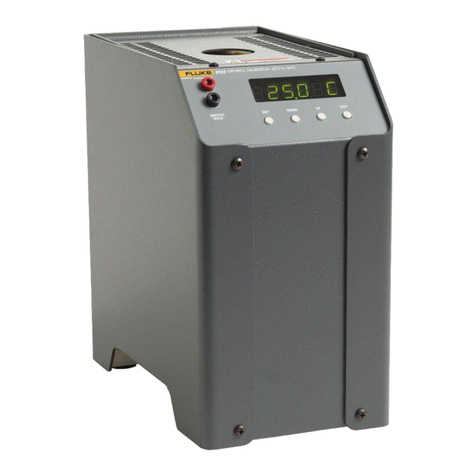
Fluke 9132 User manual

Rev. 672501 ENG
9132
Portable IR Calibrator
User’s Guide
1.888.610.7664info@Fluke-Direct.com Fluke-Direct.com

Limited Warranty & Limitation of Liability
Each product from Fluke Corporation, Hart Scientific Division (“Hart”) is warranted to be free from de-
fects in material and workmanship under normal use and service. The warranty period is one year for the
Portable IR Calibrator. The warranty period begins on the date of the shipment. Parts, product repairs, and
services are warranted for 90 days. The warranty extends only to the original buyer or end-user customer
of a Hart authorized reseller, and does not apply to fuses, disposable batteries or to any other product,
which in Hart’s opinion, has been misused, altered, neglected, or damaged by accident or abnormal condi-
tions of operation or handling. Hart warrants that software will operate substantially in accordance with its
functional specifications for 90 days and that it has been properly recorded on non-defective media. Hart
does not warrant that software will be error free or operate without interruption. Hart does not warrant
calibrations on the Portable IR Calibrator.
Hart authorized resellers shall extend this warranty on new and unused products to end-user customers
only but have no authority to extend a greater or different warranty on behalf of Hart. Warranty support is
available if product is purchased through a Hart authorized sales outlet or Buyer has paid the applicable
international price. Hart reserves the right to invoice Buyer for importation costs of repairs/replacement
parts when product purchased in one country is submitted for repair in another country.
Hart’s warranty obligation is limited, at Hart’s option, to refund of the purchase price, free of charge
repair, or replacement of a defective product which is returned to a Hart authorized service center within
the warranty period.
To obtain warranty service, contact your nearest Hart authorized service center or send the product, with
a description of the difficulty, postage, and insurance prepaid (FOB Destination), to the nearest Hart au-
thorized service center. Hart assumes no risk for damage in transit. Following warranty repair, the product
will be returned to Buyer, transportation prepaid (FOB Destination). If Hart determines that the failure
was caused by misuse, alteration, accident or abnormal condition or operation or handling, Hart will pro-
vide an estimate or repair costs and obtain authorization before commencing the work. Following repair,
the product will be returned to the Buyer transportation prepaid and the Buyer will be billed for the repair
and return transportation charges (FOB Shipping Point).
THIS WARRANTY IS BUYER’S SOLE AND EXCLUSIVE REMEDY AND IS IN LIEU OF ALL OTH-
ER WARRANTIES, EXPRESS OR IMPLIED, INCLUDING BUT NOT LIMITED TO ANY IMPLIED
WARRANTY OF MERCHANTABILITY OR FITNESS FOR A PARTICULAR PURPOSE. HART
SHALL NOT BE LIABLE FOR ANY SPECIAL, INDIRECT, INCIDENTAL. OR CONSEQUENTIAL
DAMAGES OR LOSSES, INCLUDING LOSS OF DATA, WHETHER ARISING FROM BREACH OF
WARRANTY OR BASED ON CONTRACT, TORT, RELIANCE OR ANY OTHER THEORY.
Since some countries or states do not allow limitation of the term of an implied warranty, or exclusion
or limitation of incidental or consequential damages, the limitations and exclusions of this warranty may
not apply to every buyer. If any provision of this Warranty is held invalid or unenforceable by a court of
competent jurisdiction, such holding will not affect the validity or enforceability of any other provision.
1.888.610.7664info@Fluke-Direct.com Fluke-Direct.com

Contents
1 Before You Start ....................................................................... 1
1.1 Introduction............................................................................................1
1.2 Symbols Used........................................................................................1
1.3 Safety Information ..................................................................................3
1.3.1 WARNINGS ................................................................................................... 3
1.3.2 CAUTIONS .................................................................................................... 4
1.4 Authorized Service Centers ...................................................................5
2 Specifications and Environmental Conditions...................... 7
2.1 Specifications ........................................................................................7
2.2 Environmental Conditions ......................................................................8
3 Quick Start................................................................................ 9
3.1 Unpacking ............................................................................................9
3.2 Set Up ....................................................................................................9
3.3 Power .....................................................................................................9
3.4 Setting the Temperature.........................................................................9
4 Parts and Controls................................................................. 11
4.1 Back Panel...........................................................................................11
4.2 Front Panel...........................................................................................12
5 General Operation.................................................................. 15
5.1 Changing Display Units .......................................................................15
5.2 Switching to 230 V Operation ..............................................................15
6 Controller Operation.............................................................. 17
6.1 Well Temperature .................................................................................17
6.2 Temperature Set-point .........................................................................17
6.2.1 Programmable Set-points ........................................................................... 17
6.2.2 Set-point Value ............................................................................................ 19
6.3 Temperature Scale Units......................................................................19
6.4 Scan.....................................................................................................19
6.4.1 Scan Control................................................................................................ 19
1.888.610.7664info@Fluke-Direct.com Fluke-Direct.com

6.4.2 Scan Rate.................................................................................................... 20
6.5 Set-point Resistance............................................................................20
6.6 Temperature Scale Units......................................................................20
6.7 Secondary Menu..................................................................................20
6.8 Heater Power .......................................................................................20
6.9 Proportional Band ................................................................................21
6.10 Controller Configuration.......................................................................22
6.11 Operating Parameters .........................................................................22
6.12 Serial Interface Parameters .................................................................22
6.12.1 Baud Rate ................................................................................................... 23
6.12.2 Sample Period............................................................................................. 23
6.12.3 Duplex Mode............................................................................................... 23
6.12.4 Linefeed ...................................................................................................... 23
6.13 Calibration Parameters ........................................................................24
6.13.1 R0 ................................................................................................................ 24
6.13.2 ALPHA......................................................................................................... 24
6.13.3 DELTA.......................................................................................................... 24
7 Digital Communications........................................................ 25
7.1 Serial Communications ........................................................................25
7.2 Wiring...................................................................................................25
7.2.1 Setup ........................................................................................................... 25
7.2.2 Serial Operation .......................................................................................... 26
7.3 Interface Commands ...........................................................................26
8 Calibration Procedure ........................................................... 29
8.1 Calibration Points.................................................................................29
8.2 Calibration Procedure ..........................................................................29
8.2.1 Compute DELTA .......................................................................................... 29
8.2.2 Compute R0 and ALPHA ............................................................................ 30
8.2.3 Accuracy and Repeatability........................................................................ 31
9 Maintenance ........................................................................... 33
10 Troubleshooting ..................................................................... 35
10.1 Troubleshooting Problems, Possible Causes, and Solutions...............35
10.2 Comments............................................................................................36
10.2.1 EMC Directive ............................................................................................. 36
1.888.610.7664info@Fluke-Direct.com Fluke-Direct.com

10.2.2 Low Voltage Directive (Safety) .................................................................... 36
1.888.610.7664info@Fluke-Direct.com Fluke-Direct.com

1
1 Before You Start
1 Before You Start
1.1 Introduction
The Hart Scientific 9132 Portable IR Calibrator may be used as a portable instrument or bench
top temperature calibrator for calibrating point IR thermometers. The 9132 is small enough to
use in the field, and accurate enough to use in the lab. Calibrations may be done over a range of
50°C to 500°C (122°F to 932°F). Temperature display and setability resolution of the 9132 is
0.1 degrees.
The instrument features:
Rapid heating and cooling
Hand strap
RS-232 interface capability
Built in programmable features include:
Temperature scan rate control
Eight set-point memory
Adjustable readout in °C or °F
The temperature is accurately controlled by Hart’s digital controller. The controller uses a preci-
sion platinum RTD as a sensor and controls the well temperature with a solid state relay (triac)
driven heater.
For improved uncertainties, a 0.125” external reference thermometer may be used in the cali-
bration probe hole at the top of the instrument. When using an external reference thermometer,
the unit accuracy, stability, and ambient temperature effects on the surface can be minimized.
The LED front panel continuously shows the current temperature. The temperature may be
easily set with the control buttons to any desired temperature within the specified range. The
instrument’s multiple fault protection devices insure user and instrument safety and protection.
The 9132 calibrator was designed for portability, low cost, and ease of operation. Through
proper use the instrument will provide continued accurate calibration of temperature sensors
and devices. The user should be familiar with the safety guidelines and operating procedures of
the calibrator as described in this user guide.
1.2 Symbols Used
Table 1 lists the International Electrical Symbols. Some or all of these symbols may be used on
the instrument or in this manual.
●
●
●
●
●
●
1.888.610.7664info@Fluke-Direct.com Fluke-Direct.com

9132 Portable IR Calibrator
User’s Guide
2
Table 1 Symbols
Symbol Description
AC (Alternating Current)
AC-DC
Battery
Complies with European Union directives
DC
Double Insulated
Electric Shock
Fuse
PE Ground
Hot Surface (Burn Hazard)
Read the User’s Guide (Important Information)
Off
On
1.888.610.7664info@Fluke-Direct.com Fluke-Direct.com

3
1 Before You Start
Symbol Description
Canadian Standards Association
OVERVOLTAGE (Installation) CATEGORY II, Pollution Degree 2 per IEC1010-1 refers to
the level of Impulse Withstand Voltage protection provided. Equipment of OVERVOLTAGE
CATEGORY II is energy-consuming equipment to be supplied from the fixed installation.
Examples include household, office, and laboratory appliances.
C-TIC Australian EMC mark
The European Waste Electrical and Electronic Equipment (WEEE) Directive (2002/96/
EC) mark.
1.3 Safety Information
Use this instrument only as specified in this manual. Otherwise, the protection provided by the
instrument may be impaired.
The following definitions apply to the terms “Warning” and “Caution”.
“WARNING” identifies conditions and actions that may pose hazards to the user.
“CAUTION” identifies conditions and actions that may damage the instrument being
used.
1.3.1 WARNINGS
To avoid personal injury, follow these guidelines.
BURN HAZARD – DO NOT touch the IR target surface of the unit.The temperature
of the IR target surface is the same as the actual temperature shown on the display. If
the unit is set at 500°C and the display reads 500°C, the target surface is 500°C.The top
sheet metal of the instrument may exhibit extreme temperatures for areas close to the IR
target surface. DO NOT turn off the unit at temperatures higher than 100°C. This could
create a hazardous situation. Select a set-point less than 100°C and allow the unit to cool
before turning it off.
DO NOT operate this unit without a properly grounded, properly polarized power cord.
DO NOT connect this unit to a non-grounded, non-polarized outlet.
HIGH VOLTAGE is used in the operation of this equipment. SEVERE INJURY OR
DEATH may result if personnel fail to observe safety precautions. Before working inside
the equipment, turn the power off and disconnect the power cord.
Always replace the fuse with one of the same rating, voltage, and type.
This instrument is intended for indoor use only.
Overhead clearance is required. DO NOT place this instrument under a cabinet or other
structure.
●
●
●
●
●
●
●
●
●
1.888.610.7664info@Fluke-Direct.com Fluke-Direct.com

9132 Portable IR Calibrator
User’s Guide
4
DO NOT use this unit for any application other than calibration work.
DO NOT use this unit in environments other than those listed in the user’s guide.
DO NOT operate near flammable materials.
Use of this instrument at HIGH TEMPERATURES for extended periods of time
requires caution.
Completely unattended high temperature operation is not recommended for safety
reasons.
Before initial use, after transport, and anytime the dry-well has not been energized for
more than 10 days, the calibrator must be energized for a dry-out period of 1 to 2 hours
before it can be assumed to meet all of the safety requirements of the IEC1010-1.
The instrument can generate extreme temperatures. Precautions must be taken to prevent
personal injury or damage to objects.
Use only a grounded AC mains supply of the appropriate voltage to power the
instrument. Refer to Section 3.1, Specifications for power details.
The instrument is equipped with operator accessible system fuses. If a fuse blows, it may
be due to a power surge or failure of a component. Replace the fuse once. If the fuse
blows a second time, it is likely caused by failure of a component part. If this occurs,
contact an Authorized Hart Scientific Service Center (see Section ). Always replace the
fuse with one of the same rating, voltage, and type. Never replace the fuse with one of a
higher current rating.
Follow all safety guidelines listed in the user’s manual.
Calibration Equipment should only be used by Trained Personnel.
1.3.2 CAUTIONS
DO NOT plug the unit into 230V if the heater switches and fuse holder read 115V. This
action will cause the fuses to blow and may damage the instrument.
Components and heater lifetime can be shortened by continuous high temperature
operation.
DO NOT use fluids to clean the target surface.
DO NOT change the values of the calibration constants from the factory set values. The
correct setting of these parameters is important to the safety and proper operation of the
calibrator.
DO use a ground fault interrupt device.
Operate the instrument in room temperatures between 5 and 50°C. (41–122° F). Allow
sufficient air circulation by leaving at least 6 inches of space between the instrument and
nearby objects.
The instrument is a precision instrument. Although is has been designed for optimum
durability and trouble free operation, it must be handled with care. Always carry the unit
in an upright position. The convenient fold-up handle allows one hand carrying. The
instrument should not be operated in excessively wet, oily, dusty, or dirty environments.
Do not operate near flammable materials.
Before initial use, after transport, and anytime the dry-well has not been energized
for a “dry-out” period of 1-2 hours before it can be assumed to meet all of the safety
requirements of the IEC 1010-1.
●
●
●
●
●
●
●
●
●
●
●
●
●
●
●
●
●
●
●
1.888.610.7664info@Fluke-Direct.com Fluke-Direct.com

7
2 Specifications and Environmental Conditions
2.1 Specifications
Table 2 Specifications
Range 50°C to 500°C (122°F to 932°F)
Accuracy ±0.5°C at 100°C (±0.9°F at 212°F)
±0.65°C at 300°C (±1.2°F at 572°F)
±0.8°C at 500°C (±1.4°F at 932°F)
Stability ±0.1°C at 100°C (±0.18 at 212°F)
±0.15°C at 300°C (±0.27 at 572°F)
±0.3°C at 500°C (±0.54 at 932°F)
Target Size 2.25” (57 mm)
Resolution 0.1°C or °F
Display LED, °C or °F, switchable
Heating Times 30 minutes to max (50 0176C to 500°C)
Cooling Times 30 minutes (500°C to 100°C)
Stabilization Time 10 minutes
Target Emissivity 0.95 (±0.02 from 8 to 14µM)
Aperture Diameter 2.25” (57mm)
Computer Interface RS-232 interface included with Model 9930 Interface-it control software
Power 115 VAC (±10%), 3 A or 230 VAC (±10%), 1.5 A, 50/60 Hz, switchable,
340 W
Size 4” H x 6” W x 7” D (102 x 152 x 178 mm)
Weight 4 lb. (1.8 kg)
Temperature differences between the IR surface and the reference probe are calculated as
shown in the graph in Figure 1.
9132
Gradient between probe and IR surface
-0.6
-0.5
-0.4
-0.3
-0.2
-0.1
0
50 100 150 200 250 300 350 400 450 500
Reference Probe C
delta T C
Figure 1 Temperature Gradient Between Probe and IR Target Surface
1.888.610.7664info@Fluke-Direct.com Fluke-Direct.com

9132 Portable IR Calibrator
User’s Guide
8
NOTE: As the calibrator temperature increases, the difference between the temperature
sensed by the reference thermometer and the temperature of the face of the target
increases.
2.2 Environmental Conditions
Although the instrument has been designed for optimum durability and trouble-free operation,
it must be handled with care. The instrument should not be operated in an excessively dusty or
dirty environment. Maintenance and cleaning recommendations can be found in the Mainte-
nance section of this manual.
The instrument operates safely under the following conditions:
temperature range: 5-35°C (41-95°F)
ambient relative humidity: 15-50%
pressure: 75kPa – 106kPa
mains voltage within ±10% of nominal
vibrations in the calibration environment should be minimized
altitudes less than 2,000 meters
●
●
●
●
●
●
1.888.610.7664info@Fluke-Direct.com Fluke-Direct.com

9
3 Quick Start
3 Quick Start
3.1 Unpacking
Unpack the calibrator carefully and inspect it for any damage that may have occurred during
shipment. If there is shipping damage, notify the carrier immediately.
Verify that the following components are present:
9132 Calibrator
Power Cord
User’s Guide
Serial Cable
9930 Software
3.2 Set Up
Place the calibrator on a flat surface with at least 6 inches of free space around the instrument.
The prop may be swung down to raise the front of the instrument from a horizontal position.
Plug the power cord into a grounded mains outlet. Observe that the nominal voltage corre-
sponds to that indicated on the back of the calibrator.
Turn on the power to the calibrator by toggling the power switch on. The fan should begin
quietly blowing air through the instrument and the controller display should illuminate after 3
seconds. After a brief self-test the controller should begin normal operation. If the unit fails to
operate please check the power connection.
The heater will start operating to bring the temperature of the calibrator to the set-point tem-
perature and the display will begin to show the actual target temperature.
3.3 Power
Plug the dry-well power cord into a mains outlet of the proper voltage, frequency, and current
capability. Refer to Specifications for power details. Turn the dry-well on using the rear panel
“POWER” switch. The dry-well will turn on and begin to heat to the previously programmed
temperature set-point. The front panel LED display will indicate the actual dry-well tempera-
ture.
3.4 Setting the Temperature
Section 8.2 explains in detail how to set the temperature set-point on the calibrator using the
front panel keys. The procedure is summarized here.
Press “SET” twice to access the set-point value.
Press “UP” or “DOWN” to change the set-point value.
Press “SET” to program in the new set-point.
Press “EXIT” to return to the temperature display.
●
●
●
●
●
1.
2.
3.
4.
1.888.610.7664info@Fluke-Direct.com Fluke-Direct.com

9132 Portable IR Calibrator
User’s Guide
10
When the set-point temperature is changed the controller switches the well heater on or off
to raise or lower the temperature. The displayed well temperature gradually changes until it
reaches the set-point temperature. The well may require 5 to 10 minutes to reach the set-point
depending on the span. Another 5 to 10 minutes is required to stabilize within ±0.1°C of the
set-point. Ultimate stability may take 15 to 20 minutes more of stabilization time.
1.888.610.7664info@Fluke-Direct.com Fluke-Direct.com

11
4 Parts and Controls
The user should become familiar with the calibrator and its parts.
4.1 Back Panel
The back panel (Figure 2) consists of the power cord inlet, power switch, heater voltage switch,
serial port, and fan.
115V
115V
115 VAC 50/60 Hz 340 W
230 VAC 50/60 Hz 340 W
HEATER
VOLTAGE
SWITCH RS-232
115 V - 4 A F 250 V
230 V - 2 A F 250 V
Figure 2 Back Panel
Power Inlet – At the rear of the calibrator is the removable power cord inlet that plugs into an
IEC grounded socket.
Power Switch – The power switch is located on the power entry module (PEM). The PEM also
houses the fuses and the dual voltage selector. The PEM and Heater Voltage Switch (see below)
allow the unit to be field switchable for 115 VAC (±10%) or 230 VAC (±10%) operation.
Heater Voltage Switch – To be used only when changing the input voltage. (See Section 7.2
for instructions on changing the input voltage.)
CAUTION: Do not plug the unit into 230 V if the heater switches and fuse holder read
115 V. This action will cause the fuses to blow and may damage the instrument.
Serial Port – A DB-9 male connector is present for interfacing the calibrator to a computer or
terminal with serial RS-232 communications.
1.888.610.7664info@Fluke-Direct.com Fluke-Direct.com

9132 Portable IR Calibrator
User’s Guide
12
Fan – The fan inside the calibrator has two speeds and runs continuously when the unit is being
operated to provide cooling for the instrument. The fan runs slow for heating and maintaining
operation and runs fast for rapid cooling. Slots are provided for airflow. The area around the
calibrator must be kept clear to allow adequate ventilation. The airflow is directed out the front
and can be extremely hot.
4.2 Front Panel
The front panel (Figure 3) consists of the controller display, controller keypad, and target as-
sembly.
SET UP
DOWN EXIT
9132
INFRARED
CALIBRATOR
Figure 3 Front Panel
Controller Display – The digital display displays set and actual temperatures and various
calibrator functions, settings, and constants. The display shows temperatures in units according
to the selected scale °C or °F.
Controller Keypad – The four button keypad allows easy setting of the set-point temperature.
The control buttons (SET, DOWN, UP, and EXIT) are used to set the calibrator temperature set-
point, access and set other operating parameters, and access and set calibration parameters.
Setting the control temperature is done directly in degrees of the current scale. The control
temperature can be set to one-tenth of a degree Celsius or Fahrenheit.
The functions of the buttons are as follows:
SET – Used to display the next parameter in the menu and to store parameters to the displayed
value.
DOWN – Used to decrement the displayed value of parameters.
1.888.610.7664info@Fluke-Direct.com Fluke-Direct.com

13
4 Parts and Controls
UP – Used to increment the displayed value.
EXIT – Used to exit a function and to skip to the next function. Any changes made to the dis-
played value are ignored.
Target Assembly – The target assembly is 57 mm (2.25 in) in diameter and has an emisivity of
0.95.
1.888.610.7664info@Fluke-Direct.com Fluke-Direct.com

15
5 General Operation
5 General Operation
5.1 Changing Display Units
The Model 9132 can display temperature in Celsius or Fahrenheit. The temperature units are
shipped from the factory set to Celsius. There are two ways to change to Fahrenheit or back to
Celsius as described below.
Press the “SET” and “UP” simultaneously. The units are changed.
Or
Press the “SET” key three times from the temperature display to show Un = C
Press the “UP” or “DOWN” key to change units.
5.2 Switching to 230 V Operation
The 9132 is switchable from 115 V ac to 230 V ac 50/60 Hz. Switching the voltage can change
the calibration. Therefore, we recommend that the instrument be calibrated after the voltage is
switched. To change from 115 V ac to 230 V ac follow the steps below.
Unplug the instrument.
With a small straight slot screwdriver remove the fuse holder located on the rear panel.
Replace the two 4 amps fuses with 2 amp 250 V fuses.
Replace the fuse holder with the “230V” in the display window.
Using the same straight slot screwdriver, move the heater switch to display “230V”. See
the back panel drawing in Figure 2 on page 11.
NOTE: If the heater switch and the fuse holder do not both read 230 V when complete,
the unit will either not heat or only heat at a fraction of its capacity. If not done properly,
the unit could become damaged and void the calibration and warranty. Use 4 amp fuses
for 115 V and 2 amp fuses for 230 V only.
CAUTION: Do not plug the unit into 230 V if the heater switches and fuse holder read
115 V. This action will cause the fuses to blow and may damage the instrument.
1.
1.
2.
1.
2.
3.
4.
5.
1.888.610.7664info@Fluke-Direct.com Fluke-Direct.com

17
6 Controller Operation
This chapter discusses in detail how to operate the instrument temperature controller using the
front control panel. Using the front panel key-switches and LED display the user may monitor
the well temperature, set the temperature set-point in degrees C or F, monitor the heater output
power, adjust the controller proportional band, and program the calibration parameters, operat-
ing parameters, and serial interface configuration. Operation of the functions and parameters
are shown in the flowchart in Figure on page . This chart may be copied for reference.
In the following discussion a button with the word SET, UP, EXIT or DOWN inside indicates
the panel button while the LED type text indicates the display reading. Explanation of the but-
ton or display reading are to the right of each button or display value.
6.1 Well Temperature
The digital LED display on the front panel allows direct viewing of the actual well tempera-
ture. This temperature value is what is normally shown on the display. The units, C or F, of the
temperature value are displayed at the right. For example,
100.0 C Well temperature in degrees Celsius
The temperature display function may be accessed from any other function by pressing the
“EXIT” button.
6.2 Temperature Set-point
The temperature set-point can be set to any value within the range and with resolution as given
in the specifications. Be careful not to exceed the safe upper temperature limit of any device
inserted into the well.
Setting the temperature involves selecting one of the eight set-points in memory and then ad-
justing the set-point value.
6.2.1 Programmable Set-points
The controller stores 8 set-point temperatures in memory. The set-points can be quickly recalled
to conveniently set the calibrator to a previously programmed temperature set-point.
To set the temperature one must first select the set-point memory. This function is accessed
from the temperature display function by pressing “SET”. The number of the set-point memory
currently being used is shown at the left on the display followed by the current set-point value.
100.0 C Well temperature in degrees Celsius
SAccess set-point memory
1. 100. Set-point memory 1, 100°C currently used.
To change to another set-point memory press “UP” or “DOWN”.
4. 300. New set-point memory 4, 300°C
1.888.610.7664info@Fluke-Direct.com Fluke-Direct.com

9132 Portable IR Calibrator
User’s Guide
18
Figure 4 Controller Operation Flowchart
1.888.610.7664info@Fluke-Direct.com Fluke-Direct.com

19
6 Controller Operation
Press “SET” to accept the new selection and access the set-point value.
SAccept selected set-point memory.
6.2.2 Set-point Value
The set-point value may be adjusted after selecting the set-point memory and pressing “SET”.
4. 200. Set-point 4 value in °C
If the set-point value need not be changed then press “EXIT” to resume displaying the well
temperature. To change the set-point value, press “SET” and then press “UP” or “DOWN”.
220.0 New set-point value
When the desired set-point value is reached press “SET” to accept the new value and access the
temperature scale units selection. If “EXIT” is pressed instead then any changes made to the
set-point will be ignored.
SAccept new set-point value
6.3 Temperature Scale Units
The temperature scale units of the controller maybe set by the user to degrees Celsius (°C) or
Fahrenheit (°F). The units are used in displaying the well temperature, set-point, and propor-
tional band.
Press “SET” after adjusting the set-point value to change display units.
Un=C Scale units currently selected
Press “UP” or “DOWN” to change the units.
Un=F New units selected
6.4 Scan
The scan rate can be set and enabled so that when the set-point is changed the dry-well heats or
cools at a specified rate (degrees per minute) until it reaches the new set-point. With the scan
disabled the dry-well heats or cools at the maximum possible rate.
6.4.1 Scan Control
The scan is controlled with the scan on/off function that appears in the main menu after the
temperature scale units.
Sc=OFF Scan function off
Press “UP” or “DOWN” to toggle the scan on or off.
Sc=On Scan function on
1.888.610.7664info@Fluke-Direct.com Fluke-Direct.com
Other manuals for 9132
1
Table of contents
Other Fluke Test Equipment manuals

Fluke
Fluke 190-062/AM Operation manual

Fluke
Fluke 744 User manual

Fluke
Fluke 6270A User manual

Fluke
Fluke T3 Use and care manual

Fluke
Fluke NetTool II Series User manual

Fluke
Fluke 1507 User manual

Fluke
Fluke NX1 Pocket Toner User manual

Fluke
Fluke ULT800 User manual

Fluke
Fluke 55XXA User manual

Fluke
Fluke Fiber Viewer FT120 User manual

Fluke
Fluke 5080A User manual

Fluke
Fluke FTK200 User manual

Fluke
Fluke CableIQ User manual

Fluke
Fluke 820-2 User manual

Fluke
Fluke T5-600 User manual

Fluke
Fluke 5080A/SC User manual

Fluke
Fluke 719PRO User manual

Fluke
Fluke 1623 User manual

Fluke
Fluke 718 Series Operating and installation instructions

Fluke
Fluke ScopeMeter 196 User manual