Safetytest 3N User manual

SAFETYTEST 3N Manual
SAFETYTEST
SAFETYTEST GmbH
16 April 2006
Page 1 of 18
SAFETYTEST 3N Manual
Picture 1
Texts and drawings were prepared with great care. However, errors can still be present. The
manufacturer assumes no direct or indirect liability for any damages which may occur.
Please read this manual carefully before using the leakage current clamp.
Warning markings in the manual and on the clamp are meant to warn of risks or dangers.
General warning see manual
This warning marking in the manual is intended to warn of risks or
dangers of intended or not intended use
Disregarding these warnings may result in serious injuries or death.
Warning when exchanging fuses
Warning of the risk of fire, e. g. when using improper fuses.

SAFETYTEST 3N Manual
SAFETYTEST
SAFETYTEST GmbH
16 April 2006
Page 2 of 18
Contents
1General Warnings................................................................................................. 4
2Application ............................................................................................................ 5
3Scope of Delivery.................................................................................................. 5
3.1 Standard:................................................................................................................... 5
3.2 Accessories (Optional):............................................................................................. 5
3.3 Spare parts:............................................................................................................... 5
3.4 Software (Optional):................................................................................................... 5
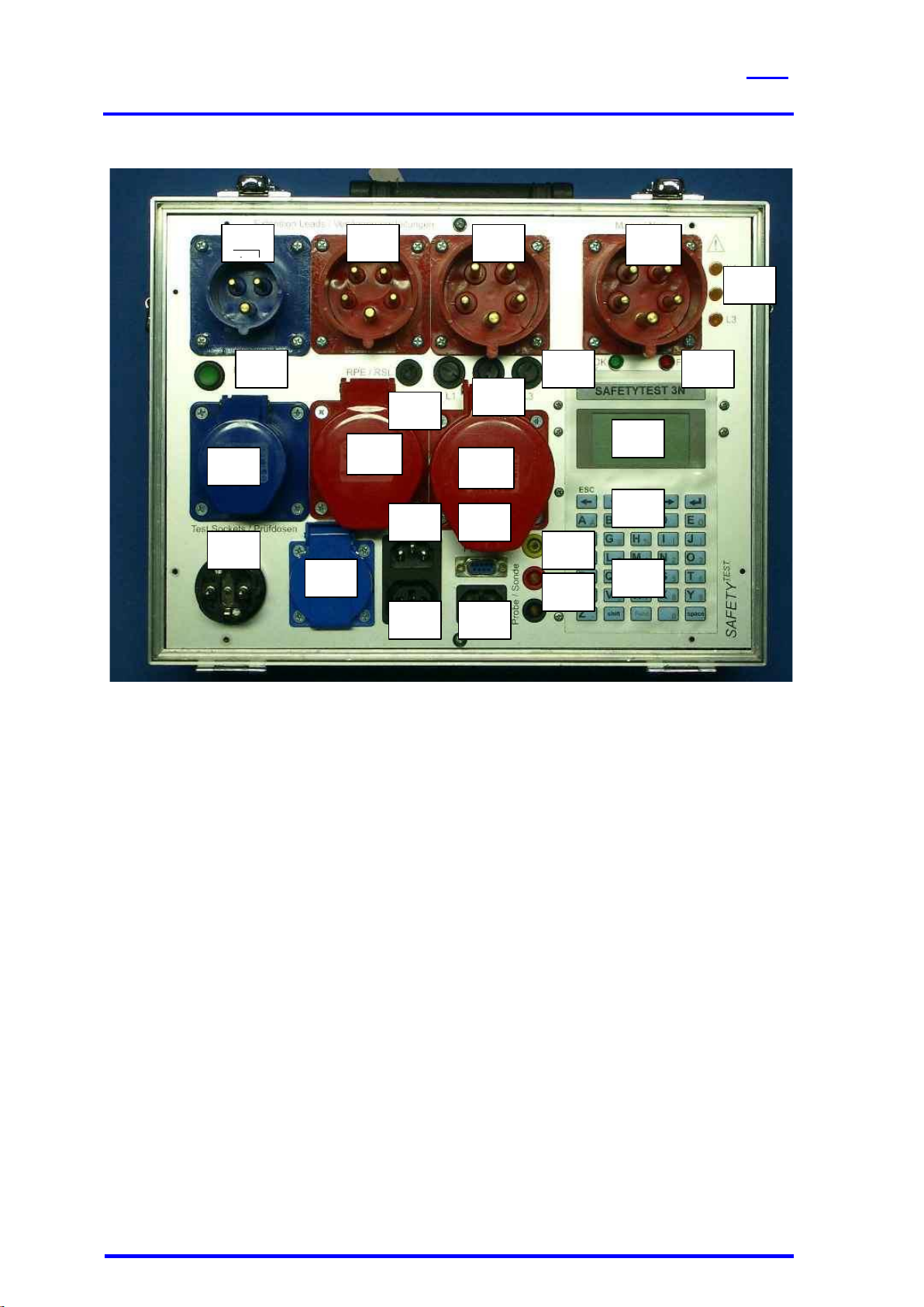
4Connections and user interface........................................................................... 6
4.1 Connections (Picture 2) ............................................................................................. 7
4.2 Mains connection “Input“, Type CEE-32A 230/400V AC (Picture 2/1)........................ 7
4.3 Measuring socket “GND“ (Picture 2/16) .................................................................... 7
4.4 Measuring sockets “Probe“ (Picture 2/17) .................................................................. 7
4.5 Interface PC-COM (Picture 2/18)............................................................................... 7
4.6 Test sockets (Picture 2/2,3,4) ................................................................................... 7
4.7 Testing plugs (picture 2/5,6,7).................................................................................... 7
4.8 Fuses F1, F2 and F3 for all 16A testing sockets (picture 2/23)................................... 8
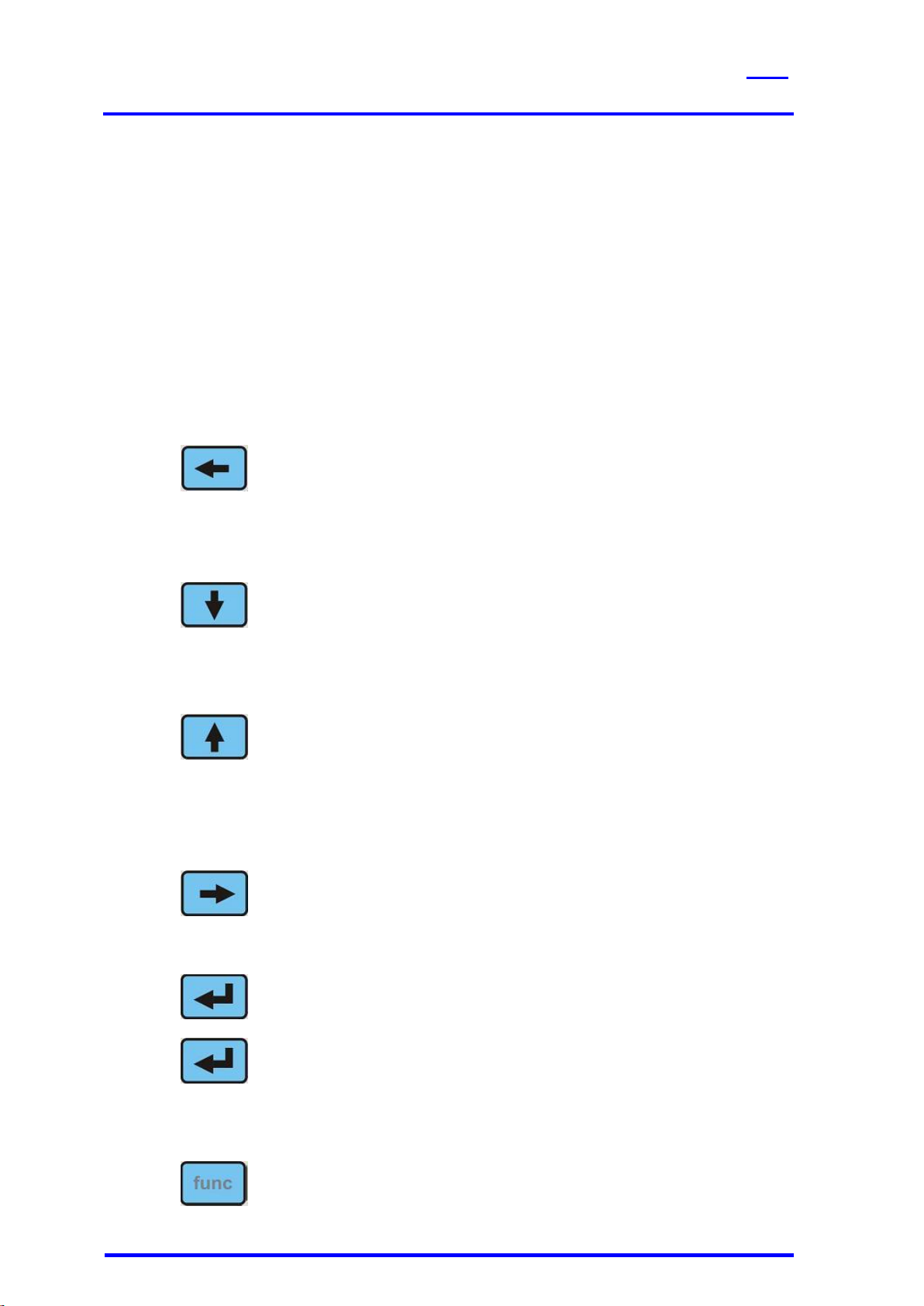
4.9 Keyboard................................................................................................................... 8
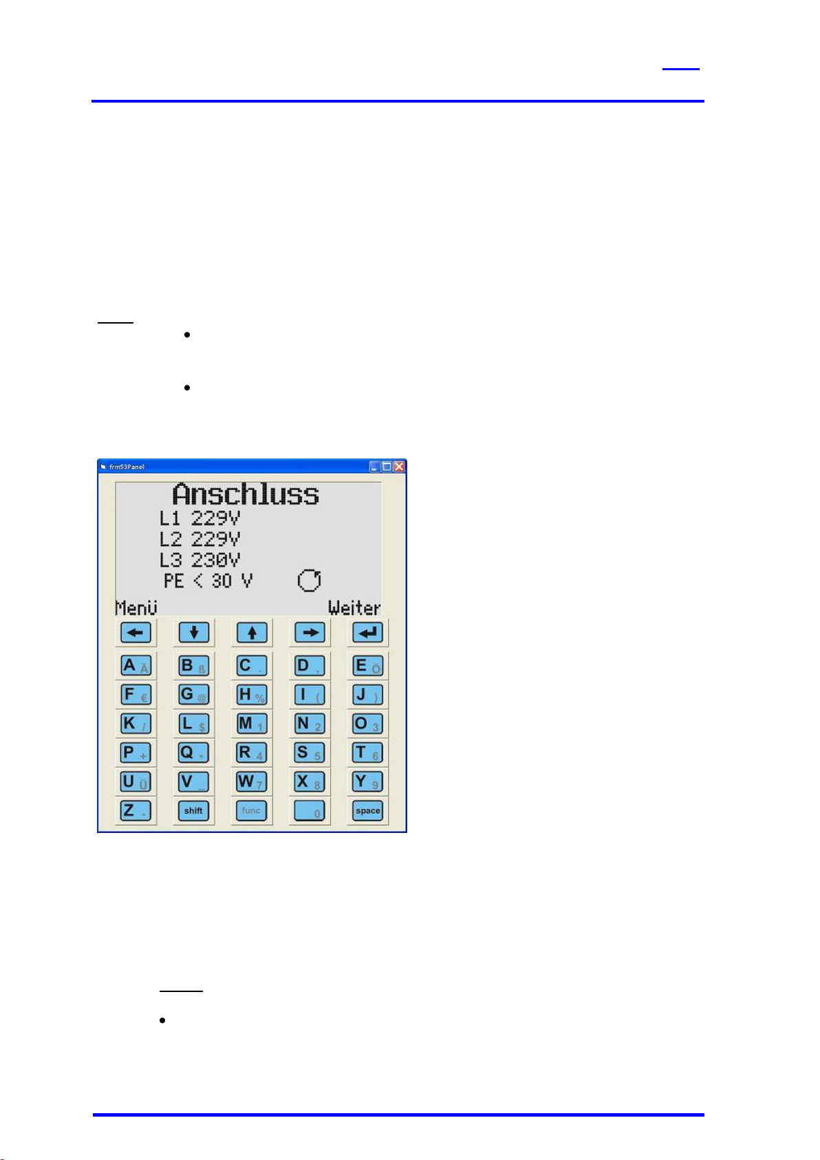
4.10 Display (Picture 2/14)................................................................................................. 8
4.11 Keyboard (Picture 2/15)............................................................................................. 8
5Functional Description......................................................................................... 9
5.1 Power supply............................................................................................................. 9
5.2 Internal memory......................................................................................................... 9
5.3 Interface RS232......................................................................................................... 9
5.4 Display and Keyboard................................................................................................ 9
5.5 Fuses......................................................................................................................... 9
6Testing the Mains Connection ............................................................................10
7Connection test....................................................................................................10
7.1 AC Supply.................................................................................................................10
7.2 Three phase connection ...........................................................................................11
8Display and Menu Structure................................................................................11
9Taking the Tester into Operation........................................................................11
9.1 Visual check .............................................................................................................11
9.2 Connecting the tester to the mains system ...............................................................11
9.3 Starting the test.........................................................................................................11

SAFETYTEST 3N Manual
SAFETYTEST
SAFETYTEST GmbH
16 April 2006
Page 3 of 18
10 Testing Electrical Appliances .............................................................................11
10.1 Qualification..............................................................................................................12
10.2 Mains connection......................................................................................................12
10.3 Visual inspection.......................................................................................................12
10.4 Measurements..........................................................................................................13
10.5 Functional test ..........................................................................................................13
10.6 Checking the markings .............................................................................................13
10.7 Documentation of the test.........................................................................................13
11 Connections, Examples.......................................................................................14
12 Updating the Firmware........................................................................................15
13 Error messages, removing faults........................................................................16
13.1 The display remains dark..........................................................................................16
13.2 Touch current display is 0,000 mA...........................................................................16
13.3 Touch current larger than 0,5 mA..............................................................................16
13.4 Leakage current measurement shows “F“ as a result................................................17
13.5 The mains voltages are displayed incorrectly............................................................17
14 Spare Parts...........................................................................................................17
15 Technical Data......................................................................................................17
16 Disposal................................................................................................................18
17 Guarantee.............................................................................................................18

SAFETYTEST 3N Manual
SAFETYTEST
SAFETYTEST GmbH
16 April 2006
Page 4 of 18
1 General Warnings
The tester “Safetytest 3N“complies to the following safety standards:
EN 61010-1
SAFETY REQUIREMENTS FOR ELECTRICAL EQUIPMENT FOR
MEASUREMENT, CONTROL, AND LABORATORY USE
DIN VDE 0404 parts 1 and 2,
In order to warrant the safe application of the tester the following warnings have to be
adhered to:
All tests may only be carried out by a skilled electrician or under the
supervision of a skilled electrician. The qualified person must be trained
for the specific task.
The tester may be subject only to its intended use. The warning
markings have to be observed.
The tester may be used only on 230/400 V AC main systems which are
protected with max 32A circuit breakers or fuses.
Repairs and alterations to the tester may be carried out only by the
manufacturer or by a service organisation qualified by the manufacturer.
Repairs on the supply leads may be carried out only by skilled
electricians.
Only original spare parts supplied by the manufacturer may be used.
The fuses F1, F2 und F3 (T16 A 250 V) may be exchanged only by
fuses of the manufacturer.
Other fuses may cause fire!
Only the adapter cables delivered by the manufacturer may be used!
If a safe application is not possible, e. g. due to:
- Visual defects,
- Improper storage,
- Improper transport,
- Failure o a phase control lamp,
- Failure of measurement functions
The tester must be decommissioned!

SAFETYTEST 3N Manual
SAFETYTEST
SAFETYTEST GmbH
16 April 2006
Page 5 of 18
Earth bond tests and touch current tests in power systems are only
allowed when regarding ht appropriate safety precautions.
Note that large voltages may appear on appliances under test, e. g. by
charged capacitors.
Connect the appliance under test only to the tester if the power system
is safe and OK.
NOTE! When connecting the appliance to mains hazardous voltages
may occur on conductive parts which are not connected to PE.
2 Application
The tester “SAFETYTEST 3N“ is used for testing the electrical safety of appliances.
3 Scope of Delivery
3.1 Standard:
Tester
Test lead
Test certificate
3.2 Accessories (Optional):
Mains chord 32 A
Adapter 32A CEE-16A CEE for connection to 16A CEEE plugs
Adapter 32 A CEE Schuko
Adapter 32A CEE-fixed connection
Crocodile clip
Brass brush probe for effective earth bond testing
Barcode scanner
Barcode printer
Transponder scanner
Small line printer
5 m probe
3.3 Spare parts:
Fuse 16AT
3.4 Software (Optional):
Remote control and database software Safety-Remote-SAFETYTEST 3N
Protocol and Excel software Safetydoc SAFETYTEST 3N

SAFETYTEST 3N Manual
SAFETYTEST
SAFETYTEST GmbH
16 April 2006
Page 6 of 18
4 Connections and user interface
1
2
3
4
5
6
7
4
8
9
10
11
12
13
14
15
16
17
18
19
20
21
22
23
24
Picture 2
1. 32 A CEE three phase plug for connection power
2. 32 A CEE three phase test socket
3. 16 A CEE three phase test socket
4. 16 A CEE AC test socket
5. 32 A CEE three phase plug for testing extension leads
6. 16 A CEE three phase plug for testing extension leads
7. 16 A CEE AC plug for testing extension leads
8. IEC power connector for the optional auxiliary power supply (normal not connected)
9. IEC power connector test socket for IEC connector couplings
10. IEC power plug for testing extension leads
11. Schuko test socket
12. Schuko plug for testing extension leads
13. LCD Display 128x64 dots back lit
14. Menu keys
15. Alphanumeric keypad for entering the appliance master data
16. Yellow GND 4mm socket for measuring temperature and voltage
17. Probe sockets force (red) and black (sense)
18. Serial COM interface for the PC or for the connection of an optional barcode reader,
transponder reader or compact printer.
19. Green OK LED indicates an PASSED test result
20. Red fault LED indicates a FAIL test result
21. Test-button for testing the integrated RCD functionality.
When the button is pressed a leakage current is simulated. If the current exceeds a
limit value the mains circuit breaker is disconnected. For reasons of safety the tester
has to be disconnected to take it into operation again.
22. Phase indicators, showing mains voltage when the circuit breaker is switched on.

SAFETYTEST 3N Manual
SAFETYTEST
SAFETYTEST GmbH
16 April 2006
Page 7 of 18
23. Phase fuses L1, L2, L3 for the 16A test sockets (use only replacement fuses supplied
by the manufacturer, since there exists danger of fire.)
24. Fuse FF 250mA for the earth bond test.
4.1 Connections (Picture 2)
Before connection the tester to mains the appropriate warnings in chapter 2 have to be
observed, as well as the warnings for the connecting leads and accessories attached. It is
safe to use the instrument only for its intended use.
4.2 Mains connection “Input“, Type CEE-32A 230/400V AC (Picture 2/1)
Mains connection of the tester to AC and three phase systems, including the N conductor.
The tester may be connected only to a 230/400V, 50/60Hz mains protected by max 32A
circuit breaker. The internal supply for the tester is taken from L1-N.
Depending on the mains socket in the wall the connection is done using the appropriate
adapter.
4.3 Measuring socket “GND“ (Picture 2/16)
Connection for the negative pole for temperature and voltage measurements.
4.4 Measuring sockets “Probe“ (Picture 2/17)
Connection for the probe for earth bond and touch current measurements
4.5 Interface PC-COM (Picture 2/18)
Connection for a 9 pin D-sub connector for the serial interface
RS 232 (19200, N, 8, 1) for :
Transferring data to and from the PC
Calibration
Firmware updates
Note: The interface may be connected to a USB port by using an optional USB-RS232
converter.
4.6 Test sockets (Picture 2/2,3,4)
The 16A mains sockets are fused via F1, F2 and F3!
NOTE!!!
When connection a faulty appliance to the test socket a hazardous voltage may occur when
mains is applied on accessible conductive parts not connected to the protective earth and on
the housing if the protective earth is out of order.
The leakage current, mains currents and power is measured via the test sockets.
Test socket “CEE 32 A (5pol)“ for appliances with CEE-plug 32 A (5pol), (picture 2/14)
Test socket “CEE 16 A (5pol)“ for appliances with CEE-plug 16 A (5pol), (picture 2/13)
Test socket “CEE 16 A (3pol)“ for appliances with CEE-plug 16 A (3pol), (picture 2/12)
Test socket “IEC plug“ for appliances with IEC plug (3pol), (picture 2/3)
Test socket “Schuko“ for appliances with Schuko plug 16A (picture 2.2)
4.7 Testing plugs (picture 2/5,6,7)
The testing plugs are used for testing extension leads. During the test the earth bonding,
insulation against PA and phase rotation is tested.

SAFETYTEST 3N Manual
SAFETYTEST
SAFETYTEST GmbH
16 April 2006
Page 8 of 18
4.8 Fuses F1, F2 and F3 for all 16A testing sockets (picture 2/23)
The 16 A testing sockets are fused by three fuses(6x32 16 AT) F1, F2 and F3 for phases L1,
L2 and L3.
4.9 Keyboard
The alphanumeric keyboard with the menu keys is used to operate the easy to use user
menu system.
4.10 Display (Picture 2/14)
The display has a resolution of 128 x 64 pixels and is backlit. The menus are displayed as
text messages.
4.11 Keyboard (Picture 2/15)
Key “Esc“
Functions:
Note:
- Key left within a menu
- Press for a long duration and the main
menu appears, press again and the
first “Connection” menu appears
Key “Down“
Functions:
Special function
- Scroll down within a menu
- Change digits within a numerical entry
Key “„Up“
Functions:
Special Function:
- Scroll up within a menu
- Change digits within a numerical entry
- If the key is pressed during a
measurement the measurement is
reset and it can be repeated.
Key “Right“
Function:
- Scroll right within a menu
Key “Enter“
Function:
- Next step
Function:
- Enter characters
Key “Func“
Function:
- Switch between numeric and
alphabetic (light and dark keys)

SAFETYTEST 3N Manual
SAFETYTEST
SAFETYTEST GmbH
16 April 2006
Page 9 of 18
Key ”Shift“
Function:
- Switch between capital and small
letters
Key ”Space“
Function:
- Space character
Alphanumeric keys.
When entering ID numbers the numerical function is pre selected.
For all other entries the alphabetical entry is pre selected.
Enter small letters by pressing the shift key.
5 Functional Description
5.1 Power supply
The transformers for the supplying the tester are protected by two internal fuses located next
to the transformers.
5.2 Internal memory
The measurements performed are stored in the internal memory. Appliance master data and
test data may be transferred to the PC. Appliance master data as well as the test profile may
also be uploaded from the PC to the tester.
5.3 Interface RS232
The PC is connected via a SUB-D 9 extension cable. An adapter USB/RS232 may also be
used.
Note: All pins must be wired through (1:1). Do not use a Null modem cable.
The baud rate is 19200 baud
The interface is galvanically isolated from the electronics and from the test sockets.
The firmware of the tester may be updated via the interface using a special update program.
A barcode reader may be connected to the interface to scan in ID numbers of the appliances
under test. The reader must be pre configured to 19200 Baud, 8 bits, no parity, 1 stop bit,
code 39. It may be connected toe the interface and the control codes may be scanned in.
A transponder reader may also be connected for scanning in the ID codes.
Note: The appropriate configuration must be made within the menu.
For printing out results a small printer may be connected to the interface.
5.4 Display and Keyboard
The display and keyboard are supplied by their own circuitry.
5.5 Fuses
F1, F2, F3 = mains fuses, T 16 A , 6,3x32, 250 V, for all 16 A testing sockets,
F4 = fuse F 250 mA, 250V, 5x20, for resistance measurement,
NOTE!!!
Please take note of the warnings of chapter 2.

SAFETYTEST 3N Manual
SAFETYTEST
SAFETYTEST GmbH
16 April 2006
Page 10 of 18
6 Testing the Mains Connection
The person responsible for the electrical installation is responsible for the safety of the power
system to which the tester is connected.
The test of the installation is not part of the appliance test. Nevertheless the tester allows a
Note: This is not a complete test as required by IEC 16557.
The test checks if there is a voltage on the N conductor against the PE conductor. Also the
mains voltages are displayed. In addition the display indicates a clockwise or anti clockwise
phase rotation of a three phase system.
Note: If the mains connection is faulty a message “Test PE connection” is
displayed on the display. Further tests may only performed after the power
system has been repaired.
If the tester is supplied from an AC system an indication may appear that the
plug connection has to be reversed. Follow this before testing.
7 Connection test
The first menu displays the phase voltages, the phase rotation and an indication of the
potential difference between the PE and N conductors of the power system.
7.1 AC Supply
If the message “Reverse connection” appears then reverse the polarity of the Schuko plug
connected to the power system.
Notes:
In the configuration “Standard” measurements may only be performed if the
mains connection is reversed.

SAFETYTEST 3N Manual
SAFETYTEST
SAFETYTEST GmbH
16 April 2006
Page 11 of 18
In the configuration “Advanced” it is possible to perform measurements in spite
of the incorrect polarity.
NOTE!!!
If the polarity is incorrect, the mains voltages are displayed incorrectly. If the
polarity is correct, the display indicates “AC” and “PE<30V”.
If the voltage L1 < 207 V or L1 > 253 V no proper measurements can be
made.
If the message “Test PE connection” appears it is most probable that the PE conductor is not
connected to the mains power socket. It may also happen that the PE conductor is
connected but that it is hazardous live.
7.2 Three phase connection
If the mains system is correct, the voltages are indicated correctly and the display displays
“PE < 30V” and the phase rotation clockwise.
If one of the conditions occurs:
L1, L2, L3 < 207 V or,
L1, L2, L3 > 253 V
No proper measurements may be made! Check the mains connection with a multimeter.
If the phase rotation is anti clockwise, most probably two phases of the power system are
exchanged.
8 Display and Menu Structure
The menu structure is documented in a separate document. It is kept up to date together with
the software.
9 Taking the Tester into Operation
9.1 Visual check
Observe the safety precautions of chapter 2.
Check the mains connection, tester and accessories
Observe all warning markings!
9.2 Connecting the tester to the mains system
For testers without auxiliary mains input the power is supplied via the 32A mains
plug.
For a tester with AUX connection connect the tester to 230 V mains via the AUX
IEC mains input.
Note: The power supply connection test is not possible anymore since the device
PE is also taken via the AUX input.
9.3 Starting the test
Follow the menu of the tester.
10 Testing Electrical Appliances
The safety of electrical appliances may be verified by testing them according to the
applicable standards. The prescribed sequence of tests must be followed. If a fault occurs
the test must be stopped.
The following sequence is performed in the automatic testing sequence
Visual inspection
Earth bond test
For class I appliances test of the earth leakage current

SAFETYTEST 3N Manual
SAFETYTEST
SAFETYTEST GmbH
16 April 2006
Page 12 of 18
For class II appliances and for isolated all conductive parts on class I appliances
test of the touch leakage current.
Functional test
Notes:
Before performing a leakage test on class I appliances the earth bond test has to be passed.
Before performing a leakage current test on class II or III appliances an insulation resistance
test has to be passed. Accessible connections and generated SELV voltages have to be
checked according to the SELV specifications.
10.1 Qualification
High requirements are set to the qualification of the skilled electrician. <all tests have to be
performed by a skilled electrician or under his supervision. The skilled electrician must follow
the rules and standards required for his work. Also it is not allowed to omit any steps which
would ensure a correct and safe use of the appliance. The liability of the skilled person
responsible for testing is especially important if no complete test is possible (e. g. due to
permanently installed equipment). If a complete test is impossible the responsible electrician
assumes the liability and has to document this on the test report.
10.2 Mains connection
The person responsible for the installation is responsible for the safety of the power system.
Tests of fixed equipment are often incomplete. It is therefore recommended to install
optionally available mains couplings in order to perform a complete test.
NOTE!!!
Electrical appliances with a nominal current above 16A must be connected to all pole circuit
breakers according to IEC 60947. These should be mounted at a height of approx 1,7 m.
Plugs and sockets of equipment rated above 16A may not be connected or disconnected
under load. Always open the circuit breaker first.
Equipment rated below 16A does not require a separate circuit breaker.
10.3 Visual inspection
The appliances are checked for externally visible damages, e. g. :
- Damages to the housing
- Suitable place of installation
- Damages to the power cord
- Deficiencies on the strain relief
- Indications of overload or improper use
- Inappropriate alterations
- Missing protective covers
- Dirt and corrosion affecting safety
- Presence of required ventilators
- Open air vents
- Tightness
- Legibility of markings
Note:
Visible damages which might impel the mechanical or electrical safe use or which might lead
to fire must be repaired immediately.

SAFETYTEST 3N Manual
SAFETYTEST
SAFETYTEST GmbH
16 April 2006
Page 13 of 18
10.4 Measurements
See Menu system
10.5 Functional test
After performing the electrical test a functional test is required.
10.6 Checking the markings
The presence of required markings must be checked and if necessary renewed.
10.7 Documentation of the test
The passed test has to be documented. If an appliance is unsafe, this must be marked
clearly on the appliance and the responsible body to be notified in writing. The measurement
values and alterations performed are to be documented. The appliance should be marked by
a sticker.

SAFETYTEST 3N Manual
SAFETYTEST
SAFETYTEST GmbH
16 April 2006
Page 14 of 18
11 Connections, Examples
Earth bond test: Use the probe to test all conductive parts connected to PE

SAFETYTEST 3N Manual
SAFETYTEST
SAFETYTEST GmbH
16 April 2006
Page 15 of 18
Testing conductive parts not connected to PE: Use the probe to test these parts. If there
are rotating or moving parts test these in motion. The best way is to use the optional brass
brush probe. Use protective glasses.
Insulation resistance test LN-PE, Substitute leakage test: Connect appliance to test
socket. Switch on the appliance. The test is done without applying mains.
Earth leakage test, functional test: Connect the appliance to the test socket. The appliance
is tested with mains applied to it.
12 Updating the Firmware
Connect the tester to the COM interface of the PC.
Press the “ESC“ button while applying power to the tester.

SAFETYTEST 3N Manual
SAFETYTEST
SAFETYTEST GmbH
16 April 2006
Page 16 of 18
Start the PC-program Bootloader.exe
Setup the baud rate to19200Bd
Set the Com port.
Set the com port and the baud rate.
If in doubt of the com port go to WINDOWS device manager/system/hardware and check
the hardware configuration
Open File, „Open Hex File“
Select the correct hex file.
Click on „Write Flash“
Note:
After flashing the tester is restarted.
13 Error messages, removing faults
13.1 The display remains dark
Note: Possibly there is no N connection on the mains socket. Possibly one of the fuses of the
tester has blown.
13.2 Touch current display is 0,000 mA
This is no error but the safe condition.
13.3 Touch current larger than 0,5 mA
Note! Do not touch the appliance under test; there is a hazardous voltage on the accessible
parts!!!
Disconnect the appliance from mains!!!

SAFETYTEST 3N Manual
SAFETYTEST
SAFETYTEST GmbH
16 April 2006
Page 17 of 18
Perform an insulation resistance measurement between the appliance mains plug and the
accessible conductive parts not connected to PE. All switches of the appliance must be
closed. If there is a circuit breaker inside it must be bridged.
The measurement value must exceed 2 MOhm.
13.4 Leakage current measurement shows “F“ as a result
The tester regards the heating power when performing the test. Check the measurement
value to the allowed limits. If it exceeds the value, disconnect the unit under test from mains.
Do an insulation resistance measurement LN-PE. All switches have to be closed, internal
contactors bridged. Also measure the capacitance between LN and PE.
13.5 The mains voltages are displayed incorrectly
Check the mains voltages with a Multimeter. If the tester display is incorrect send it in for
servicing.
14 Spare Parts
NOTE!!!
Observe the warnings of chapter 2!
Use only spare parts supplied by the manufacturer.
The tester may be serviced only by the manufacturer or by a service shop authorised by the
manufacturer.
15 Technical Data
Mains connection: 4 wire + PE three phase or AC 400/230V +/- 10%.
Switching current: Integrated industrial contactor: 40A.
Temperature: 0°C –40°C.
Measurements (Error max. 1% of range + 5% of displayed value):
PE conductivity: 0,000 Ohm ...4,000 Ohm. OC voltage 6V, Current 200mA DC.
Insulation resistance measurement: 0,00MOhm...20,00MOhm
Oper. circuit voltages 500V, 1000V,
Short circuit current 1 mA.
Equivalent leakage current: 0,00mA ...40,00 mA,
Open circuit voltage approx. ca. 150V.
Differential current: 0,00mA...40,00mA. Filter characteristic according to DIN VDE 0404 for
correct evaluation of the harmonic currents.
Touch current: 0,000mA ... 4,000mA
Phase voltage: 0,0V...260,0V
Phase current: 0,00A ... 40,00 A
Power: 0W ... 40000W. Evaluation up to the 15th harmonic.
Phase rotation: AC, clockwise, Error
PE monitor: Voltage N-PE> 30V.
Integrated leakage current power off: Differential current > approx. 20 mA.
Temperature measurement: 1°C/mV
Voltage: 0...400V.
Test sequences:
Standard DIN VDE 0701/DIN VDE 0702
Class I active / passive (Powered / without mains)
Class II
Fixed connection
Extension lead
Single measurements

SAFETYTEST 3N Manual
SAFETYTEST
SAFETYTEST GmbH
16 April 2006
Page 18 of 18
Interface:
RS232. USB via adapter. Can be remotely controlled.
Memory, Real time clock:
approx. 1000 measurement sequences with time and date.
16 Disposal
The disposal of a decommissioned tester must be carried out by the customer according to
the national regulations.
17 Guarantee
The tester is subject to a strict quality assurance system
A calibration certificate with the documentation of the test results is delivered together with
the tester.
This certificate should always be available.
The guarantee period is for 12 months after delivery. Manufacturing defects are free of
charge. Parts underlying wear and tear like sockets, plugs, fuses, batteries, mechanical parts
are not covered by the guarantee.
Transport costs have to and from the customer for transports outside Germany have to be
covered by the customer. For transports within Germany the manufacturer pays for the
transport costs to the customer if no special service is required.
Transport and costs for use of substitute equipment must be carried by the customer.
Table of contents
Other Safetytest Test Equipment manuals