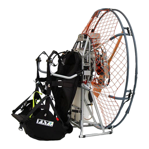
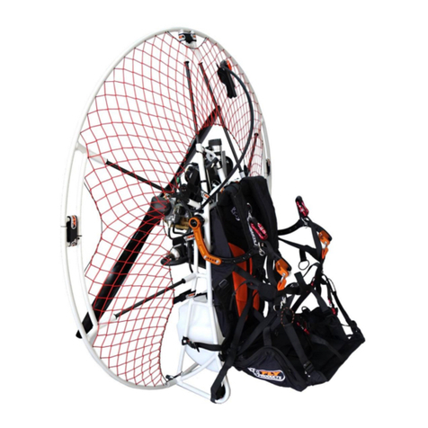
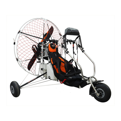
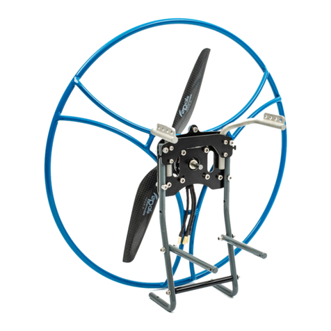
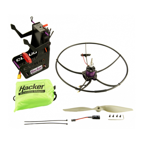
Fly Products ECLIPSE-RIDER User manual

VER. 1.1 –ENG
© Copyright by
FLY
Products s.r.l.
Via Perù n. 30 - 63066 GROTTAMMARE (AP) - ITALY
Tel. +39.735.632486 - www.flyproducts.com - fly@flyproducts.com

ECLIPSE–RIDER USER MANUAL__ _____________ ___ VER. 1.1
Pag. 2

ECLIPSE–RIDER USER MANUAL_____________ ___ VER. 1.1
© Copyright
FLY
Products s.r.l. Pag. 3
USER
MANUAL
FRAME
PAG. 6
HARNESS
PAG. 22
SETTINGS
PAG. 28
PROPELLER
PAG. 39
HANDGRIP
PAG. 40
WARRANTY
PAG. 41

ECLIPSE–RIDER USER MANUAL__ _____________ ___ VER. 1.1
Pag. 4
FIRST SAFETY! - WHO, WHERE AND WHEN CAN FLY IT.
Powered Para Gliding (PPG) is the most exciting, least expensive, safest and most accessible
form of aviation available! However, it is still aviation, and carries with it all the potential
inherent dangers of aviation, which is why it is imperative that prior to flying with this PPG it
is necessary to receive adequate training from qualified instructors and obtain a valid PPG
license. Give the Paramotor the attention that all the aviation deserves, to respect the norms,
the weather conditions and to realize that the pilot who is fully responsible for his own safety
and for the safety of fellow pilots and bystanders. Depending on each national regulation, the
Paramotor can only be used in authorized areas and flights within controlled airspace usually
require an authorization issued via radio, furthermore additional requirements such as a valid
insurance must be met.
Because of the inherent risks in flying any Paramotor, no warranty of any kind can be made
against equipment failures, accidents and even fatal injuries.
This Paramotor is not covered by product liability insurance.
Used Notations
In this manual, we will use some special terms for notations:
(NOTE, ATTENTION, WARNING) Their use is defined below.
A NOTE provides additional information to help clarify a point that is made in the text.
Generally, a NOTE is provided to facilitate product assembly, use or maintenance.
Ignoring a NOTE could cause inconvenience but not cause damage or personal injury.
The CAUTION notation provides additional information to help clarify an area where
equipment damage could occur. Failure to observe a CAUTION can result in permanent and
significant mechanical damage; however, it is unlikely to cause personal injury.
A WARNING provides additional information to help clarify an area where failure to follow a
WARNING can result in serious injury or even death.
ECLIPSE and RIDER features
FLY PRODUCTS presents these very light, but robust, Paramotors whose features are great
versatility and ease in disassembly and assembly.

ECLIPSE–RIDER USER MANUAL_____________ ___ VER. 1.1
© Copyright
FLY
Products s.r.l. Pag. 5
Overall dimensions
MODEL
H(cm/in.)
L(cm/in.)
S(cm/in.)
ECLIPSE (MAX PROPELLER 130)
142/55.9
142/55.9
Engine ATOM = 45/17.7
RIDER PROPELLER 130 MONO RIM
146/57.5
144/56.7
Engine MOSTER = 42/16.5
RIDER PROPELLER 130 DOUBLE RIM
150/59.0
143/56.3
Engine THOR 202 = 50/19.6
RIDER PROPELLER 140 MONO RIM
153/60.2
153/60.2
RIDER PROPELLER 140 DOUBLE RIM
155/61.0
155/61.0
* Note: central frame RIDER can fit all RIDER configurations:
mono/double rim for 130 cm/51.1 in. propeller
mono/double rim for 140 cm/55.1 in. propeller
The Paramotor can be disassembled,
folded and inserted into the special
trolley (optional) to be easily stored,
transported or even shipped.
The trolley sizes are:
cm 100 x 57 x 40 (in. 39.3 x 22.4 x 15.7)
* for max 130 propeller models
cm 115 x 57 x 40 (in. 45.3 x 22.4 x 15.7)
* for max 140 propeller models

ECLIPSE–RIDER USER MANUAL__ _____________ ___ VER. 1.1
Pag. 6
FRAME ASSEMBLY
The engagement system used "clip
button" or snap button, greatly simplifies
the assembly procedure.
For a correct use, keeping the button
pressed, engage the two parts and rotate
them slightly until the clicking button
comes out of the hole.
For disassembly, just keep the button
pressed down until doing a slight pull
and rotation until the hole is released
from the button thus allowing the
separation of the two parts.
The supports of the cage to be mounted on the central
frame are of THREE different lengths as shown in the
figure:
A: LONG –up
B: AVERAGE –center
C: SHORT –low
The other removable part: DIt is the starter support
for housing the engine starting pulley.
N O T I C E
JUST THE FIRST ASSEMBLY, AS THE NET IS NEW,
IT IS NORMAL TO EXERCISE A GREATER FORCE
THAN USUAL IN ASSEMBLING THE PARTS.
YOU CAN PROCEED WITHOUT FEAR OF DAMAGE.

ECLIPSE–RIDER USER MANUAL_____________ ___ VER. 1.1
© Copyright
FLY
Products s.r.l. Pag. 7
NOTE : Pay attention to the correct pulley positioning inside the support.
To start:Insert the starter
support “D” on the central
engine frame first.
1) Hook the starting pulley on
the starter support as shown
in the figure.
2) Insert the LONG (A) rods in
the central frame.
Complete the insertion of the rods
according to the length, as
previously indicated, in the
appropriate housings:
(A) LONG rods
(B) MEDIUM rods
(C) SHORT rods

ECLIPSE–RIDER USER MANUAL__ _____________ ___ VER. 1.1
Pag. 8
Begin assembling the outer frame circle by following the procedure:
Insert the two lower parts of the circle, right and left, into the
SHORT rods (C) by slightly forcing the rods upwards.
1
2
3
4
5
4-5
1
Thread the two upper parts of the cage
without joining them together,
the connection will be made after inserting
the remaining parts of the cage.
2-3
Insert the two parts of the cage, right and
left, into the MEDIUM rods (B) by slightly
forcing the rods upwards to facilitate the
operation.

ECLIPSE–RIDER USER MANUAL_____________ ___ VER. 1.1
© Copyright
FLY
Products s.r.l. Pag. 9
Once all the insertions of the external frame into the slats have been
completed, proceed to the lower RIGHT and LEFT coupling, checking
that the sealing button has come out correctly from its hole and the
part is actually locked.
Then proceed to the RIGHT and LEFT lateral connection of the two lower
and upper semicircles, checking that the sealing button has come out
correctly from its hole and that the part is actually locked.
6
7
8
9
6-7
8-9

ECLIPSE–RIDER USER MANUAL__ _____________ ___ VER. 1.1
Pag. 10
Open the velcro and pass it through the prepared eyelet following the direction
indicated.
Pull the velcro until you have the
maximum tension of the net.
Lock the velcro in correct position by
pressing it on the underlying loop.
10
Connect the two upper
semicircles together, always
checking that the sealing button
has come out correctly from its
hole and that the coupling is
actually firm.
10
To complete the assembly of the cage,
hook the RIGHT and LEFT side velcro straps as follows:

ECLIPSE–RIDER USER MANUAL_____________ ___ VER. 1.1
© Copyright
FLY
Products s.r.l. Pag. 11
Turn the velcro around the loop and
lock it properly in place.
Firmly tighten parts to ensure
complete matching.
Finally, join the lower plastic buckles to fix and perfectly stretch the net:
Hook the parts making sure the buckle is
perfectly sealed.
Lock the coupling by moving the button as
shown in the figure.
This operation ends the assembly of the protection cage.
REPEAT THE SAME OPERATION ON THE OTHER SIDE

ECLIPSE–RIDER USER MANUAL__ _____________ ___ VER. 1.1
Pag. 12
To disassemble the cage avoiding to force some parts too much and avoid possible
damage, we recommend proceeding with the following sequence of operations:
CAGE DISASSEMBLY
1-2 3-4
Start by unlocking the safety of the
lower plastic buckle and unlock it,
repeat the same operation on the
other side before continuing.
1-3
2
4

ECLIPSE–RIDER USER MANUAL_____________ ___ VER. 1.1
© Copyright
FLY
Products s.r.l. Pag. 13
5-6
Unlock and release
the net from the
RIGHT and LEFT
side velcro straps,
taking care to close
the velcros on
itself.
5
5
6
7-8
Uncouple the upper cage
from the lower one by
pressing the push-pin
button and pulling the
upper part upwards.
Repeat the operation
on the other side
7
5
8
5
9
Uncouple the upper cage by
pressing the push-pin button
and pulling the parts in the
opposite direction.
DO NOT REMOVE NOW
from the support rods !
9
5

ECLIPSE–RIDER USER MANUAL__ _____________ ___ VER. 1.1
Pag. 14
10-11
Unhook the lower cage by pressing the push-pin button
and pulling the part outwards.
Repeat the operation on the other side
10
5
11
5
12-13
Slide the lower cage out of the rods while holding them firmly in place.
Repeat the operation on the other side
12
5
13
5

ECLIPSE–RIDER USER MANUAL_____________ ___ VER. 1.1
© Copyright
FLY
Products s.r.l. Pag. 15
14-15
Remove the upper SIDE cage from the rods, holding them firmly in place.
Repeat the operation on the other side
16
Join together the two plastic
buckles of the disassembled
net below.
14
5
15
5
16
5
17
5
17
Lift the two lower semicircles
to the top with the nets
joined by the plastic buckles
and hold the four parts at the
same time before removing.

ECLIPSE–RIDER USER MANUAL__ _____________ ___ VER. 1.1
Pag. 16
This operation ends the disassembly of the cage.
18-19
Remove the last two semicircles from the rods and fold everything in a booklet so that
the cage is ready and folded in the correct way to put it back in its bag.
18
5
19
5
STORAGE OF THE CAGE
Place the rods in the special pocket inside
the bag prepared for this purpose,
then put the cage already folded up
carefully and close the bag with the string.

ECLIPSE–RIDER USER MANUAL_____________ ___ VER. 1.1
© Copyright
FLY
Products s.r.l. Pag. 17
The assembly and disassembly operations of the single rim frame of
the RIDER series are identical to the ECLIPSE frame, therefore it is
advisable to follow the procedure explained above.
RIDER SINGLE RIM FRAME
The only differences are the
double upper attachment and
the two double lateral
attachments.

ECLIPSE–RIDER USER MANUAL__ _____________ ___ VER. 1.1
Pag. 18
1
5
2
5
3
5
In order not to force the net excessively, it is recommended follow the
illustrated sequence with the parts DETACHED from each other taking
care to insert points "4" AT THE SAME TIME and finally again at the
same time points "5" making sure the snap pins are perfectly inserted.
When all the parts are in place, you can proceed to the complete
junction of the rim and the subsequent locking it with the prepared
velcro straps.
RIDER DOUBLE RIM FRAME ASSEMBLY
4
5
5
5
4
5
AT THE SAME TIME
AT THE SAME TIME
5
5

ECLIPSE–RIDER USER MANUAL_____________ ___ VER. 1.1
© Copyright
FLY
Products s.r.l. Pag. 19
DOUBLE RIM RIDER FRAME DISASSEMBLY
For disassembly, after opening all the closing velcro straps,
(it is good norm to close them on itself to prevent
they stick to the net in the subsequent operations)
detach all the joints of the outer rim starting from points A–B
and continue with points C-D-E.
Then, following the order illustrated above, PULL OUT the parts from
the support ribs 1-2-3-4-5taking care to remove AT THE SAME TIME
first points "1" and then again AT THE SAME TIME points "2".
1
5
4
5
3
5
5
5
2
5
A
5
E
5
B
5
C
5
D
5
AT THE SAME TIME
AT THE SAME TIME

ECLIPSE–RIDER USER MANUAL__ _____________ ___ VER. 1.1
Pag. 20
Turn the strap around the tube between the two velcroes, and close them to stop it.
Place the tank in the correct position onto its supports and lock it as shown below.
MOUNT THE TANK
Table of contents
Other Fly Products Paramotor manuals

Fly Products
Fly Products FLASH CRUISER User manual

Fly Products
Fly Products FLASH 100 User manual

Fly Products
Fly Products Eco 2 Light User manual

Fly Products
Fly Products GOLD 95 User manual

Fly Products
Fly Products XENIT II User manual

Fly Products
Fly Products POWER JET User manual

Fly Products
Fly Products MAX 100 User manual

Fly Products
Fly Products FOXY mini TRIKE User manual

Fly Products
Fly Products VERTIGO User manual

Fly Products
Fly Products Rider Series User manual