Fly Products Kompress User manual


“KOMPRESS”OWNER’SMANUAL REL .2.0
_________________________________________________________________________
© Copyright by FLY Products s.r.l. Page
2
INDEX
Page Chapter Description
20Index
41.0 INTRODUCTION AND GENERAL INFORMATION
41.1 Safety first! -Who, Where and When can fly it.
41.2 Notation used
41.3 Congratulations on your new "KOMPRESS"
51.4 Kompress features
51.5 Diagram of components
62.0 UNPACKING AND ASSEMBLING YOUR "KOMPRESS"
62.1 Frame assembly
92.2 Harness mounting
11 2.3 Prop mounting
12 2.4 Spark plug
12 2.5 Assembly inspection
12 3.0 PREPARING YOUR FIRST FLIGHT
12 3.1 Fuel and oil
13 3.2 Before starting the engine
13 3.3 Starting and stopping the engine
13 3.3.1 Stopping the engine
14 3.3.2 Starting the engine
15 3.4 Carburettor adjusting
16 3.5 Engine break-in
16 3.6 Harness adjusting
17 3.6.1 Ground handling straps
18 3.6.2 Flight straps
18 3.6.3 Hang test in a simulator
19 4.0 FLYING YOUR "KOMPRESS"
19 4.1 Pre-flight inspection
19 4.2 Pre-flight checklist examples
21 4.3Flight under special conditions
22 4.4Dangerous situation
23 5.0 OPTIONAL ACCESSORIES
23 5.1 Tool kit
23 5.2 Reserve Parachute
23 5.3 Speed Bar
24 6.0 PACKING YOUR "KOMPRESS" FOR TRAVEL
24 6.1 Disassembling for local travel
24 6.2 Disassembling and packing for long-distance travel
24 6.2.1 Fuel tank drain
24 6.2.2 Draining all fuel
24 6.2.3 Removing the harness
24 6.2.4 Cage disassembly
INDEX

“KOMPRESS”OWNER’SMANUAL REL .2.0
_________________________________________________________________________
© Copyright by FLY Products s.r.l. Page
3
Page Chapter Description
25 7.0 MAINTENANCE
26 7.1 Regular checks obligation
26 7.2 Maintenance overview
28 7.3 Cleaning
28 7.4 Prop care
28 7.5 Spark plug
28 7.6 Repairs
29 7.7 Reduction belt
29 7.8 Long term storage
30 7.9 Paraglider
30 7.10 Paraglider inspections
31 8.0 TROUBLESHOOTING
31 8.1 Diagnosing and starting a flooded engine
31 8.2 Troubleshooting chart
32 9.0 SPECIFICATION AND PERFORMANCE
32 9.1 Specification and performance summary chart
33 9.2 Torque specification chart
34 9.3 Electric system
36 10.0 MISCELLANEOUS
36 10.1 Obtain repair parts
38 10.2 Warranty
38 10.3 Internet info and upgrades
1.0 INTRODUCTION AND GENERAL INFORMATION

“KOMPRESS”OWNER’SMANUAL REL .2.0
_________________________________________________________________________
© Copyright by FLY Products s.r.l. Page
4
1.1 Safety first, WWW!(Who, Where and When can fly it)
Powered Para Gliding (PPG) is the most exciting, least expensive, safest, and most accessible form of
aviation available! However, it is still aviation, and it brings with it all the inherent potential dangers
of aviation. People can, and do, get hurt, and even killed, in any form of aviation, including PPG.
For that reason it is imperative that before fly with this PPG you must receive proper training from
qualified instructors and obtain a valid PPG license, an then offer PPG the respect all aviation
deserves, respect weather and conditions, and realize that in the end, it is the pilot himself that is fully
responsible for his own safety and the safety of fellow pilots and bystanders.
Depending on every national regulations, the PPG may only be operated in authorized areas and
flights within controlled airspace usually needs a permission given by radio.
Additional requirements like a valid insurance must be fulfilled.
Powered Paragliding is an extremely demanding sport that requires exceptional levels of attention,
judgment, maturity, self-discipline, and attention to detail. It is unlikely that you will be able to
participate in it safely unless you make a conscious and continual commitment to your own safety.
Due to the inherent risks in flying this or any PPG, no warranty of any kind can be made against
accidents, bodily injury, equipment failure, and/or death.
This PPG is not covered by product liability insurance. Do not start it or fly it unless you are
willing to assume all risks inherent in the sport of Powered Paragliding and all responsibility for
any property damage, injury, or death which may result from the use of this product.
Please read and be sure you thoroughly understand this Operator’s Manual before starting or flying
your KOMPRESS. It contains information critical to the safe operation of the Powered Para Glider.
1.2 Notation used
Certain special terms (NOTE, CAUTION, WARNING) will be used throughout this manual. Their
usage is defined below.
A NOTE provides supplemental information to help clarify a point being made in the text. Generally,
a “note” is provided to help assembly, use, or maintenance of the product. Disregarding a “note”
could cause inconvenience, but would not cause damage or personal injury.
A CAUTION provides supplemental information to help clarify an area where equipment damage
could occur. Disregarding a “caution” could result in permanent and significant mechanical damage,
however personal injury is unlikely.
A WARNING provides supplemental information to help clarify an area where personal injury or
death could occur from negligence. Disregarding a warning” could result in serious injury or death.
1.3 Congratulations on your new KOMPRESS
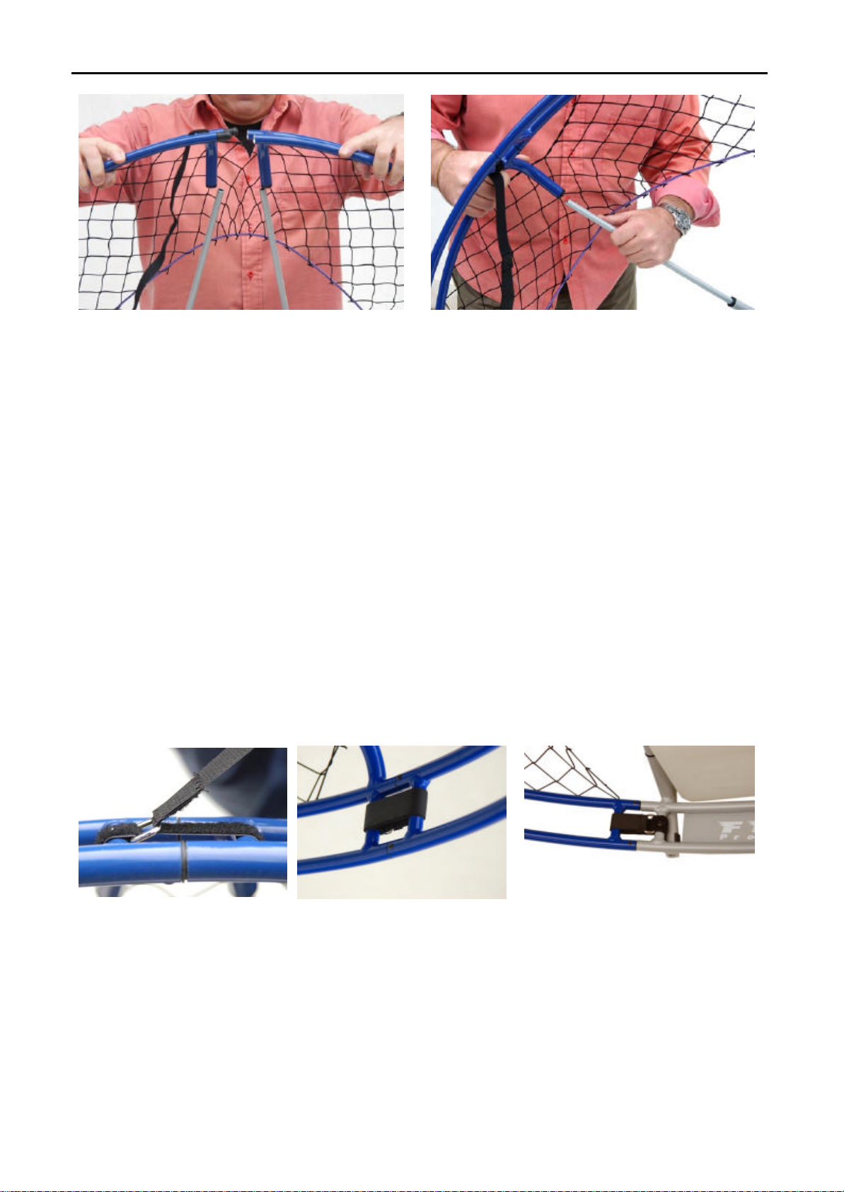
Kompress is Fly Products latest design built for easy and compact transportation using a new fully
detachable frame. With a new cage construction, incorporating a simple to use attachment method,
the Kompress is truly compact. The Black Devil M25 engine has proven to have an excellent weight-
to-thrust ratio matched with low noise level and efficient fuel consumption.
1.4 KOMPRESS features
?Easy assembly and disassembly
?Electric Starter
?Power Ignition
?Reduction drive
?Air cooling

“KOMPRESS”OWNER’SMANUAL REL .2.0
_________________________________________________________________________
© Copyright by FLY Products s.r.l. Page
5
?Tuned Pipe
?Extremely quiet
?In-flight Restarting
?Very good fuel economy and duration.
1.5 Diagram of Components
Fig. 1 -Rear View of unit
1 – External cage
2 – Multifunction throttle handgrip
3 – Silenced air filter
4 – Muffler/tuned pipe
5 – Fuel Tank
6 – External base frame
Fig. 2 – Side view:
1 – Manual pull starter
2 – Distance bar
3 – Main on/off security switch
4 – Harness
5 – Fuel pump
2.0 UNPACKING AND ASSEMBLING
“KOMPRESS”
2.1 Frame assembly
Frame assembly and disassembly is very fast and easy.
The outer frame consists of four parts, and they are held together by the velcro straps.

“KOMPRESS”OWNER’SMANUAL REL .2.0
_________________________________________________________________________
© Copyright by FLY Products s.r.l. Page
6
Fig. 3
Fig. 4 Unpacked unit view
For an easy and correct assembly proceed in the following order:
Step 1: Place the KOMPRESS’s lower base frame part on a flat surface and insert the 4 little tubes on
it fig. 5–Base connection points
Step 3:Connect the two base frames with the two lateral velcro straps as in Fig. 7
Step 4:Connect the two fuel lines of the fuel tank as in Fig. 8
Step 5:Connect the little fuel pump line as in Fig. 9
This complete the base mounting.
Step 2: Hold down the lower base frame with a foot
and let the engine’s frame descend into the four
inserts as shown in fig. 6
fig.6–base connection

“KOMPRESS”OWNER’SMANUAL REL .2.0
_________________________________________________________________________
© Copyright by FLY Products s.r.l. Page
7
Fig. 7-side lock
Fig. 8 – fuel lines connect
Fig. 9 – mini pump connect
Step6 : Assembling outer frames
Fig. 10-supports Fig.11 – starter pulley section Fig. 12 – Tube supports mounting
Tube supports (fig. 10) are in three pairs in two different lengths.
Prepare the “A” tube supports into the upper part
Mount the other external cage supports as shown in fig. 12.
NOTE:You might want to add that assembling the cage in this order is the easiest way.
Step7 : Assembling upper frames
Insert the two upper supports “C” into their seating as in fig. 13.

“KOMPRESS”OWNER’SMANUAL REL .2.0
_________________________________________________________________________
© Copyright by FLY Products s.r.l. Page
8
Fig. 13 – Mount the cage into the upper
supports Fig. 14 – upper side connection
Step5 : Assembling right hand side outer frame
Insert the two upper-side pins into their seating as in fig. 14.
Mount the left hand side outer frame repeating the previous step 5
Insert the two lower–side pins of the frame into their seating as in fig. 16
Mount the other lower-side outer frame repeating the same operation.
Step6 : Assembling lower outer frame
Insert the two lower pins of the frame into their seating as in fig. 17
Mount the other lower outer frame repeating the same operation.
Step7 : Attachthe velcro straps.
Once the frame is properly connected, it is best to immediately attachthe velcro straps as shown in
fig. 15A-B-C
Fig. 15 A– Attachthe upper Fig. 15 B– Attachthe sides Fig. 15C– Attachthe lowers
NOTE!When finished, check all velcro straps Attachments.
Step8 : Net stretching.

“KOMPRESS”OWNER’SMANUAL REL .2.0
_________________________________________________________________________
© Copyright by FLY Products s.r.l. Page
9
Final operation is the net stretching
and locking. Thread the stretching
string ends as shown in fig.16, thread
the hook-end into the noose-end,
stretch the string and hook back to
the "flying" loop.
Fig. 16 – Lower noose loop
This completes the assembly of the external cage.
2.2 Harness mounting
The harness mounts to the central frame with six attachment points.
They are: the top harness triangular carabiners, the ground handling straps, and the distance bars.
Fig. 17 – upper hooks harness attachment
Step1:
First engage the harness to the central unit
by hooking the two triangular carabiners to
the eyelets bolts as shown in fig. 17.
CAUTION – Close the carabiners immediately
in order to avoid forgetting them later.
Fig. 18 – distance bar attachment to the central frame
Step 2:
insert the two distance bars into their frame seats as
shown in Fig. 18

“KOMPRESS”OWNER’SMANUAL REL .2.0
_________________________________________________________________________
© Copyright by FLY Products s.r.l. Page
10
Fig. 19 – front harness webbing attachment
Step 3:
Ensure that the harness is attached correctly to the
distance bars and the web straps can freely slide into
their seats as shown in fig 19.
Fig. 20 –21 Lower harness
attachment
Step 3:Next, attach the two
bottom harness straps as shown in
Fig. 20-21. Fasten these belts
securely as shown in close up
detail. Do this for the left and right
sides. Leave these straps at their
loosest setting for now, we’ll
adjust them later.

“KOMPRESS”OWNER’SMANUAL REL .2.0
_________________________________________________________________________
© Copyright by FLY Products s.r.l. Page
11
Fig. 22 – Upper harness attachment
Fig. 23 – Seat set-up
The harness has 2 attach position, use the “A” position for paramotor use and “B” for trike operation.
As shown in fig. 22, the “C” distance can be regulated from 28 to 32 cm.
You can also regulate the harness-seat keeping closed or opened the seat zipper as shown in fig. 23.
This completes the harness mounting. Double check your work to ensure that everything is OK.
MENTION ON DISTANCE BARS:
These distance bars are extremely easy to mount and dismount since they slide easily into the central
frame. The end of the distance bars are made of a square aluminum profile that does not allow them to
rotate. Due to the compression of the harness, the distance bars can not slide out of their fittings during
flight.
Fig. 24 Distance bar system.
ANTI-TORQUE SISTEM
The distance bars are designed to allow the
sliding of the front harness webbing so that the
pilot finds the proper angle with the paraglider.
With this system the force of the propeller torque
onto the risers is avoided.
Depending on the engine, the torque can be to the
left or the right, in the case of VITTORAZI
engine the torque is to the right.
LATERAL MOVEMENT OF DISTANCE BARS.
The distance bars allow a lateral movement which is useful for the pilot to enter easily into the
harness.

“KOMPRESS”OWNER’SMANUAL REL .2.0
_________________________________________________________________________
© Copyright by FLY Products s.r.l. Page
12
Low connections

“KOMPRESS”OWNER’SMANUAL REL .2.0
_________________________________________________________________________
© Copyright by FLY Products s.r.l. Page
13
2.3Prop mounting
Mounting the prop is quick and easy.
Place the rear prop flange on the rear side of the prop.
Insert the six (6) prop bolts through the rear prop flange and
prop.
The correct torque to use is 12 Nm
A more practical “field method” of torquing is to tighten the
bolts snuggly and evenly, but not enough to begin to crush
the wood of the prop.
Fig. 25 – mounting the prop,
the red arrow indicate the direction of propeller rotation.
2.4 Spark plug
Set the spark plug gap to 0.025” (0.635mm). Install the spark plug and torque to specifications
(120-inch lbs. or 10 ft-lbs.).
2.5 Assembly inspection

“KOMPRESS”OWNER’SMANUAL REL .2.0
_________________________________________________________________________
© Copyright by FLY Products s.r.l. Page
14
It is critical to fully inspect the assembly of the KOMPRESS to find and remedy any potential problem
areas before proceeding.
The inspection should contain, at a minimum, the following items:
?Review each assembly step above
?Examine all nuts, bolts, and fasteners for security
?Check the harness for correct mounting, that all straps are secure, that there are no
twists on any straps
?Examine prop cage for correct assembly, that it is strong, the netting is tight and on the
correct side
?Check that nothing can get in the prop. The prop should clear the cage by same distance at
all points.
?Check the fuel tank and fuel delivery system.
?Check for correct mounting of prop, and correct torque of prop bolts.
3.0 PREPARING FOR YOUR FIRST FLIGHT
3.1 Fuel and Oil
FLY PRODUCTS recommends the use of a premium unleaded automotive gasoline of 92 octane or
higher, and the use of premium synthetic 2-cycle oil. Mix fresh gas and oil before each flying session.
Store your fuel/oil mixture in an approved, sealed container. Dispose of fuel/oil mixture that is older
than 72 hours.
The recommended fuel/oil ratio is 2%. Be sure to thoroughly agitate the mixture to completely
dissolve the oil.
Use only fresh fuel and oil, and use clean containers, funnels, hoses, etc.
To fill the fuel tank, remove the fuel tank by unscrewing the fuel tank cap . Take care not to get dirt,
dust, etc. onto the fuel pickup.
It is recommended that the fuel be poured into the tank using a straining-type of funnel.
Fill the tank with the desired amount of fuel.. Tighten the fuel cap securely.
CAUTION: Wipe up any spilled fuel immediately, as the fuel/oil mixture is highly flammable, and an
in-flight fire would be catastrophic.
Also, the oil will leave a residue, which will attract and retain dust and dirt.
WARNING! Use common sense when refueling. Do not refuel a hot or running engine,
do not smoke or allow on-lookers to smoke while refueling. Do not refuel near heat or open flame
3.2 Before Starting the Engine

“KOMPRESS”OWNER’SMANUAL REL .2.0
_________________________________________________________________________
© Copyright by FLY Products s.r.l. Page
15
Before starting the engine on the ground, ensure that the unit is in an area free from dirt, rocks, dust,
etc.
that could be sucked up and thrown around by the propeller.
Check assembly of the unit, and especially check any and all nuts, bolts, and screws, that could be
loose.
Also check all parts of the prop cage for looseness. The prop produces a significant amount of thrust,
and can suck things into it from a surprising distance.
WARNING! Ensure that no bystanders or onlookers are close by when starting the motor.
The most dangerous place to stand is in the plane of the propeller. This is where dust, dirt, rocks, nuts,
bolts, etc. will be thrown if they are picked up by the prop.
At full RPM, the prop tips are moving in excess of 370mph, and pushing the air rearward at over
70mph.
This amount of force can pick up anything loose in the area and throw it around like a bullet.
Not only can it severely injure you or bystanders, even small items like dirt can inflict significant
damage to the prop
3.3 Starting and stopping engine
3.3.1 Stopping the engine
Before of proceed it's better to learn the function of the handgrip:
A– STOP” button
B– “START” button
C– Throttle lever
D– Cruise control setup
E– Velcro strap
Fig. 26 – Multifunction handgrip F– LED light for low fuel indication
Since it’s important to know how to stop the engine once it’s started, let’s cover “Stopping the Engine”
first. To stop the engine, simply depress the “STOP” button (A -fig. 26) and hold it until the engine
comes to a complete stop.
CAUTION: It is important to be aware of some other engine stopping techniques, should the stop
switch not function correctly.
The stop switch may not function correctly due to
1) faulty switch,
2) broken wires,
3) bad connections to any part of the stop switch circuitry
For this reason, the following emergency stop procedures are available:

“KOMPRESS”OWNER’SMANUAL REL .2.0
_________________________________________________________________________
© Copyright by FLY Products s.r.l. Page
16
To stop the engine if the stop switch doesn’t function correctly, you can
?Unplug the electric cap of the spark plug
(there is a big risk to take an electric-shock, not dangerous but unpleasant...)
?Squeeze the fuel line
(requires an aggressive squeeze, and takes about two minutes to stop the motor).
3.3.2 Starting the engine
Now that we’ve covered stopping the motor, let’s start the engine!
Check that the fuel tube is full. If it isn't, use the designated fuel pump to fill it up.
Be careful to not pump more than necessary to avoid engine flooding.
To start the cold engine it's necessary to inject fuel into the cylinder, to do this, squeeze the pump
only once while holding the accelerator completely open until you hear the fuel squirt from the
carburetor into the cylinder.
Allow a certain quantity of fuel to enter the carburetor but not enough to allow it to go out of the
air filter, if this happens, this means that the engine could be flooded and will hesitate to start .
If everything is ready and well done, flip the main
ignition switch (security switch) to the “ON
" position
(Fig. 27)
Fig. 27 – Main security switch
OPEN the fuel tank vent cock
in this position:
There are three different positions that can be used to start the engine. These positions are:
?Standing in front of the unit, holding the unit on the ground.
?Strapped into the unit, standing on the ground
?In flight.
We’ll cover each of these starting options in turn.
-Standing in front of the unit, holding the unit on the ground
WARNING! The method of holding the throttle handle is important in this position.
Hold the throttle handle such that you can easily reach the stop button, but not so that you can
inadvertently squeeze the throttle (do not strap your hand to throttle at this point).
A common accident can happen where you hold the throttle in the same hand that you hold the
motor unit, and if you squeeze the throttle a little, the thrust of the machine will push the throttle
onto your hand, causing you to squeeze the throttle even more.
Make sure that you CANNOT inadvertently squeeze the throttle handle when starting in this position.
-Stand in front of the unit, and place your left hand on the top of the central frame tube. Hold the
throttle in your right hand , noting the warning above.

“KOMPRESS”OWNER’SMANUAL REL .2.0
_________________________________________________________________________
© Copyright by FLY Products s.r.l. Page
17
-Depress the START button until the engine starts. The engine should start after a few propeller
turns.
-Strapped into the unit, standing on the ground
Just depress the START button once you are ready, strapped and standing on the ground.
-In flight:
One very valuable feature of the KOMPRESS series is its ability to be started while in flight.
This feature allows the pilot the freedom to turn-off the engine and glide silently, to enjoy the
exhilaration of thermal soaring, and then when he gets low, re-start the engine depressing the START
button and climb back up to do it again.
WARNING! It's very important that immediately after landing, or when the equipment is not in use
on the ground, to turn the main security switch (Fig. 27) to the OFF position to avoid an accidental
starting of the engine!
3.4 Carburetor Adjusting
The carburator has two screws for adjustment, one screw marked L
adjusting idle speed and low rpm and one screw marked Hfor high
rpm.
In order to make the adjustment, tighten clockwise then unscrew:
screw Lfrom 3/4 (three quarter) turn to one full turn, screw Hfrom 1
1/4 (one and a quarter) to 1 1/2 (one and a half) turn This adjustment
is done for the air filter Air Box (Kart model), we advise this kind of
air filter.
Furthermore, we recommend attaching a small security-cable to the
air filter, to avoid it slipping off and hitting against the propeller.
These adjustments can change based on weather conditions and flight
altitudes.
The ideal mixture is reached when the insulator of the spark plug
is light brown (the color of coffee with milk); if the colour is black,
the mixture is too rich, therefore turn screw Hclockwise 1/8 round
per time.
If the spark plug is grey/white, the mixture is lean, therefore turn
screw Hand Lcounterclockwise always 1/8 round per time. Remember that if the mixture is too lean,
THE PISTON CAN SEIZE.
You can see better the color of the spark plug by running the engine for 20 seconds at full throttle
and switching it off suddenly without letting it slow down.
Once you have found the perfect mixture do not change it unless you change where you fly or the
conditions you fly in, since the register screws can be damaged by continuous adjustments.
CAUTION: It is important NOT to adjust your carburetor to a point where it is running on a
excessively lean mixture, especially at the high setting.
A lean mixture will result in a overheating of the engine due to lack of proper cylinder lubrication.
If the is too rich there is not damage to the cylinder , except for an increased , gradual build up of
carbon residue which can easily be cleaned off.
Fig. 28 – H/Lscrews
settings

“KOMPRESS”OWNER’SMANUAL REL .2.0
_________________________________________________________________________
© Copyright by FLY Products s.r.l. Page
18
If you have any doubt any modifications you’ve made to your carburetor setting then adjust towards
a richer mixture.
A simple way to check if your carburetor setting is correct is to examine the electrode of the spark
plug after having run the engine for 20-30 minutes, if the electrode is:
-light brown = the setting is correct
-grey = the setting is too lean
-black = the setting is too rich.
3.5 Engine Break-In.
Break-in of the KOMPRESS’ s BLACK DEVIL engine is required before the first flight. Proper
break-in will provide you with a better running engine, it will also provide for considerably longer
engine life.
During the break-in, gently change RPM from idle to 3/4-throttle and back.
All BLACK DEVIL engines, before being delivered, are subject to a severe quality-check, in order
to verify that all the components are within the proper parameters, but a further breaking-in is
anyway necessary.
Just for this period of break-in use fuel mixture at 3% ( then return to normal use at 2% of oil).
Go to a quiet place, put a thick rubber carpet under your unit to avoid stones or other things that
could damage the propeller by putting it on the ground and continue as follows: let the engine run at
a speed of 2500 rpm for 5 minutes, then regulate speed at 3000/3500 rpm for 15 minutes, then at
4000 rpm for other 15 minutes. Switch off the engine and check that there are no loose nuts or bolts
and that every component is OK. BE CAREFUL NOT TO TOUCH HOT PARTS (POWER UNIT AND
EXHAUST PIPE).
Start the engine again and take it step by step to 4000 rpm for 5 minutes, then accelerate to 4500 rpm
for 15 minutes. During the first 10 hours, do not subject the engine to extend periods of high rpm
especially for excessive loads (ex. tandems with passenger) that could over stress the engine and
possibly damage it.
ALWAYS VISUALLY CHECK your unit before and after the flight, so that you can see if some
part has been loosened, damaged or presents any abnormalities. After each flight, in the version
with decompressor, clean the head of any oil residue.
At this point, you can fly the KOMPRESS, however avoid long periods of full power, and vary the
throttle setting often.
3.6 Harness Adjustment.
The harness consists of two separate strapping systems, one used to comfortably support the
paramotor assembly unit on the pilot’s back while on the ground, and the other is used to support the
paramotor and pilot while flying. This system also correctly aligns the thrust angle of the prop.

“KOMPRESS”OWNER’SMANUAL REL .2.0
_________________________________________________________________________
© Copyright by FLY Products s.r.l. Page
19
Fig. 29 Front and Side views of ground handling straps (GREEN)and the flight straps(RED)
The two systems have separate purposes, and are adjusted separately
3.6.1 Ground Handling Straps
The ground handling straps as shown above are best adjusted standing on the ground, with the
KOMPRESS on the pilot’s back.
The purpose of the shoulder straps and shoulder pads is to carry the weight of the KOMPRESS
while on the ground.
The purpose of the ground handling chest strap is to keep the shoulder pads from sliding off the
pilot’s shoulders when ground handling.
The adjustment procedure for the ground handling straps is as follows:
?Strap into the paramotor and stand up.
?Adjust the Shoulder Straps until the shoulder pads are carrying the weight of the paramotor.
?Attach snug the ground handling chest strap .
?Adjust the thigh straps, the tightness of the thigh straps will determine how easily you can slide
into the seat after takeoff , allowing the width of your hand between the strap and your leg is
generally a good setting.
The ground handling straps are adjusted correctly if:
?The weight of the paramotor is on the shoulder pads
?The shoulder pads/straps won’t fall off the shoulders
?The seat can be moved out from under the buttocks easily
?You can slide easily in and out the seat
?You can run easily and the seat and thigh straps don’t interfere with your ability to run.
3.6.2 Flight Straps

“KOMPRESS”OWNER’SMANUAL REL .2.0
_________________________________________________________________________
© Copyright by FLY Products s.r.l. Page
20
The purpose of each flight strap ( in fig. 23. are shown in red )
is as follows:
?Length “B” determines the carabiner height.
Higher accommodates larger pilots.
Lower accommodates smaller pilots and provides more weight
shift capability. This length has a variable adjustment locations.
?Length “C” is adjusted by buckle, and it sets the thrust angle.
Adjust it so the thrust angle is five to tendegrees below horizontal.
This must be done in a simulator.
See “Hang Test in a Simulator” below.
?Length "D", is used to adjust the back of pilot's distance from
the PPG.
?Proceed to final adjusting of the harness in the simulator..
Fig. 30 Set-up of flight straps
3.6.2 Hang-test in a Simulator
It is imperative that you perform a hang-test in a simulator before the initial flight of the
KOMPRESS, and every time you make a harness adjustment thereafter. A simulator can consist of
two ropes tied to a horizontal (and strong) tree limb, two ropes tied to rafters in your garage or
basement, etc.
Once you have made your initial adjustments, strap into the KOMPRESS and clip the carabiners
into the simulator. Gently lift your feet and slide into the harness.
Continue to adjust the harness until the following criteria are met:
?The ground-handling straps should be loose and comfortable
?The ground handling chest strap should be loose (still buckled, but loose)
?No part of the harness should hamper free movement of your arms and the throttle cable.
Make sure you can reach your arms up very high with no strain or interference from the harness
4.0 FLYING YOUR KOMPRESS
4.1 Pre-flight Inspection
Before your first flight, and before every flight, it is absolutely essential to perform a pre-flight
inspection on your aircraft.
WARNING! Failure to perform a sufficient preflight has been a contributing factor to accidents in
all kinds of aircraft. Equipment damage, bodily injury, even death can occur due to equipment
problems not caught in a preflight inspection.
As the saying goes, “Preflight as if your life depends on it, because it does!”
Other manuals for Kompress
1
Table of contents
Other Fly Products Paramotor manuals

Fly Products
Fly Products Eco 2 Light User manual

Fly Products
Fly Products XENIT II User manual

Fly Products
Fly Products FLASH 100 User manual

Fly Products
Fly Products FLASH CRUISER User manual

Fly Products
Fly Products VERTIGO User manual

Fly Products
Fly Products GOLD 95 User manual

Fly Products
Fly Products ECLIPSE-RIDER User manual

Fly Products
Fly Products Thrust User manual

Fly Products
Fly Products FOXY mini TRIKE User manual

Fly Products
Fly Products MAX 100 User manual