Fly Products POWER JET User manual

POWER JET
OWNER'S MANUAL
Released on March 2002 (rev. 1.0)
©Copyright by FLY Products s.r.l.
Via C. Battisti, 13
63013 GROTTAMMARE (AP) - ITALY
tel./fax +39.735.632486

OWNER'S MANUAL POWER JET Rev. 1.0
©Copyright by FLY Products s.r.l. Page 2
INDEX
1.0 - FLY PRODUCTS WORLD..................................................................................................................................................3
1.1 Safety First!....................................................................................................................................................................3
1.2 Notation Used.................................................................................................................................................................3
1.3 Congratulations on Your New POWER JET!..................................................................................................................4
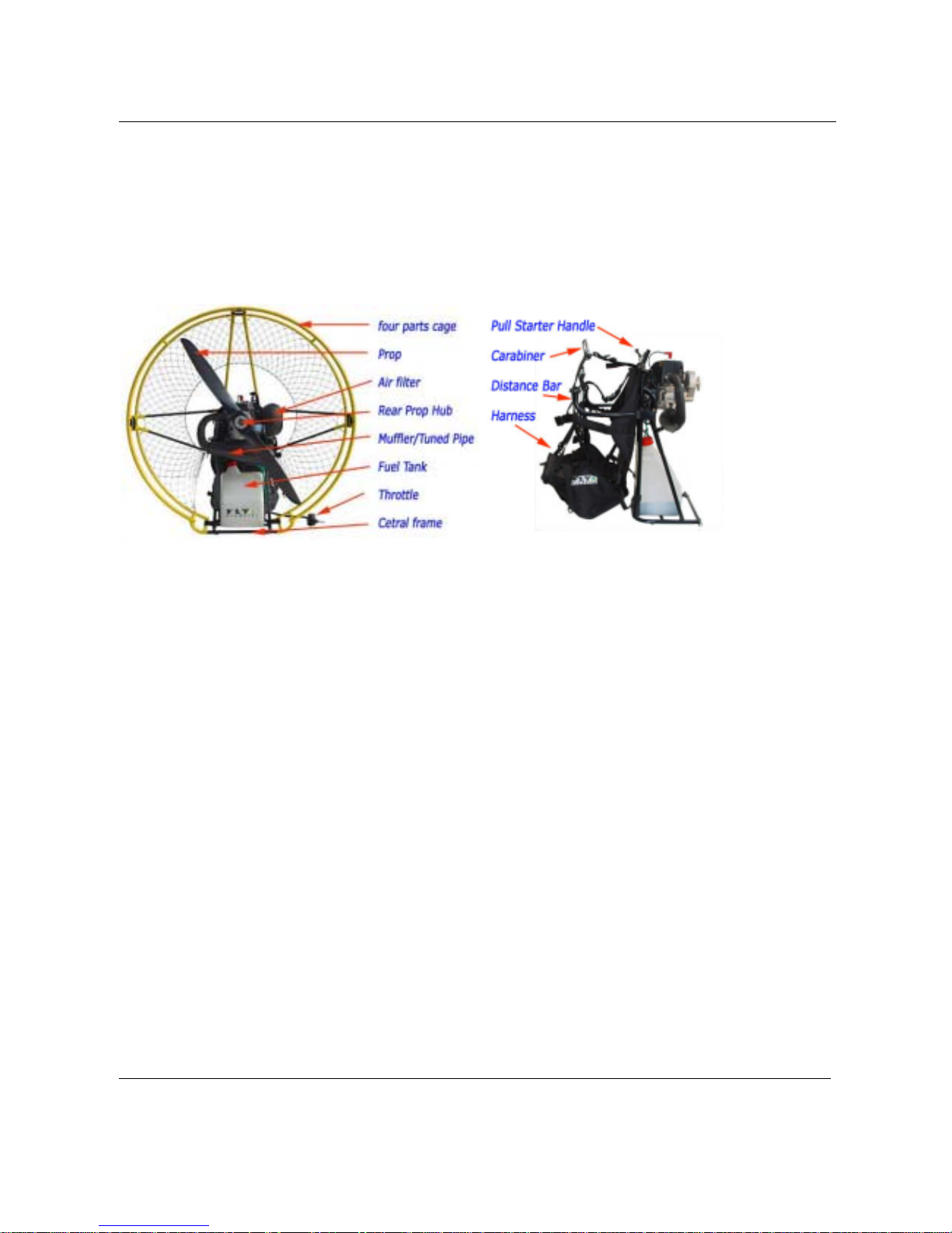
1.4 POWER JET Features ...................................................................................................................................................4
2.0 - UNPACKING AND ASSEMBLING YOUR POWER JET.....................................................................................................6
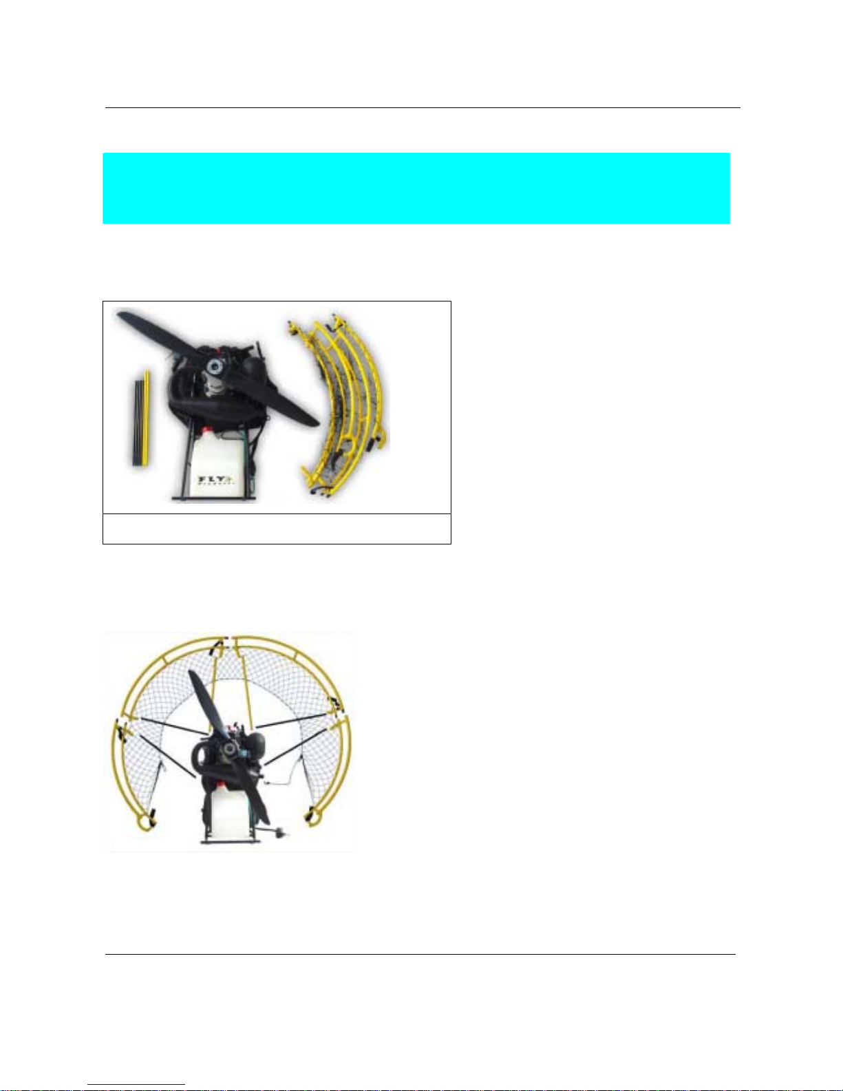
2.1 Package Contents..........................................................................................................................................................6
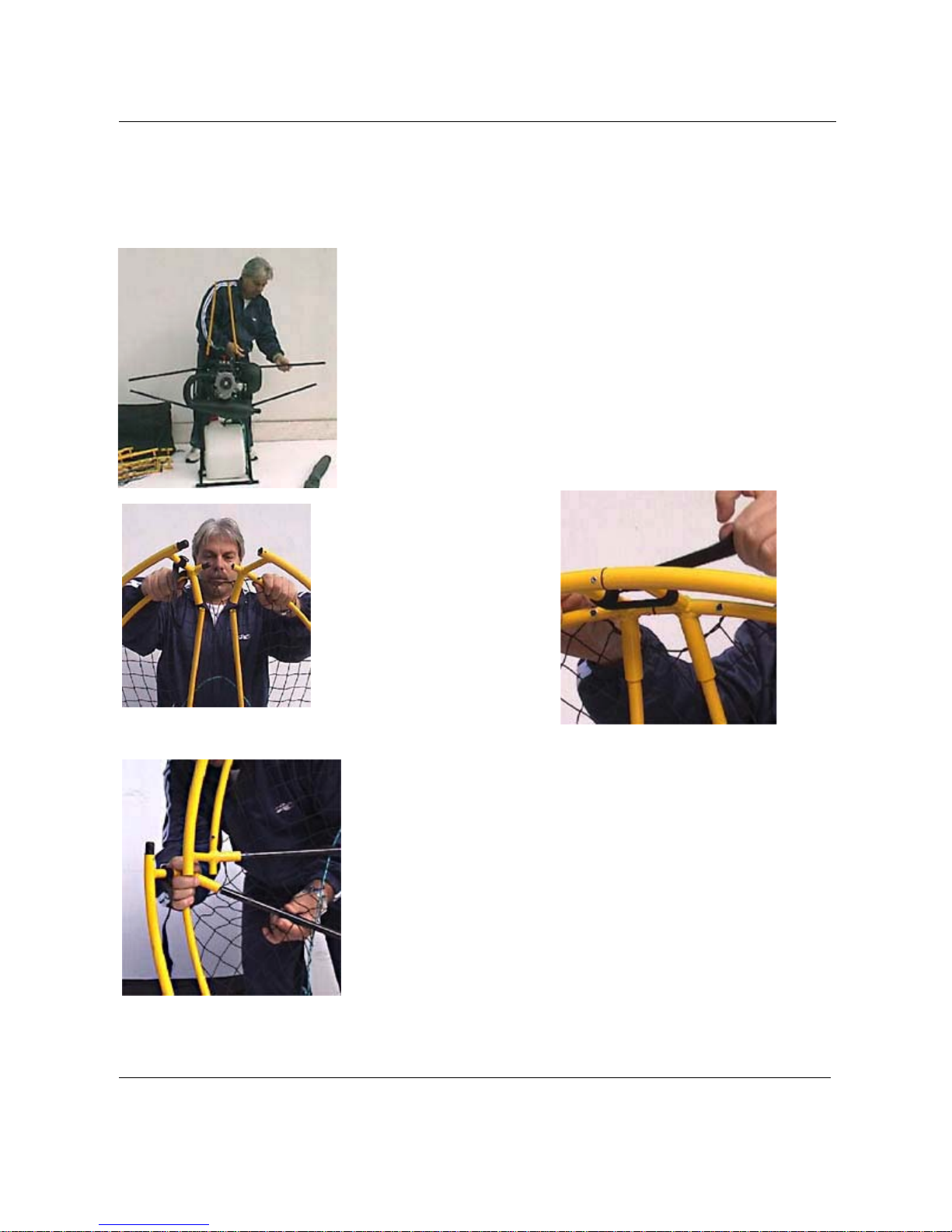
2.2 Frame Assembly.............................................................................................................................................................6
For correct assembly proceed in the following order: ........................................................................................................7
2.3 Harness Mounting ..........................................................................................................................................................9
2.4 Prop Mounting..............................................................................................................................................................11
2.5 Spark Plug...................................................................................................................................................................12
2.6 Assembly Inspection.....................................................................................................................................................12
3.0 - PREPARING FOR YOUR FIRST FLIGHT........................................................................................................................12
3.1 Fuel and Oil..................................................................................................................................................................12
3.2 Before Starting the Engine ...........................................................................................................................................13
3.3 Starting and Stopping Engine.......................................................................................................................................13
3.3.1 Stopping the Engine .............................................................................................................................................13
3.3.2 Starting the Engine...............................................................................................................................................14
3.3.3 Choking the engine...............................................................................................................................................15
3.4 Carburetor Adjusting.....................................................................................................................................................16
3.5 Engine Break-In............................................................................................................................................................17
3.6 Harness Adjustment.....................................................................................................................................................17
3.6.1 Ground Handling Straps.......................................................................................................................................18
3.6.2 Flight Straps..........................................................................................................................................................19
3.6.3 Hang-test in a Simulator.......................................................................................................................................20
4.0 - FLYING YOUR POWER JET............................................................................................................................................21
4.1 Preflight Inspection..................................................................................................................................................21
4.2 In-flight Starting ............................................................................................................................................................21
5.0 - OPTIONAL ACCESSORIES.............................................................................................................................................22
5.1 Tool Kit.........................................................................................................................................................................22
5.2 Reserve Parachute.......................................................................................................................................................22
5.3 Speed Bar ....................................................................................................................................................................22
5.4 Fuel Viewing Mirror........................................................................................................................................................23
6.0 - PACKING YOUR POWER JET FOR TRAVEL.................................................................................................................23
6.1 Disassembling for local travel.......................................................................................................................................23
6.1.1 Disassembling the Prop Cage ..............................................................................................................................23
6.2 Disassembling and packing for long-distance travel.....................................................................................................23
6.2.1 Fuel Tank drain.....................................................................................................................................................24
6.2.2 Draining All Fuel ...................................................................................................................................................24
6.2.3 Removing The Harness........................................................................................................................................24
6.2.4 Cage Disassembly................................................................................................................................................24
7.0 - MAINTENANCE................................................................................................................................................................25
7.1 Cleaning.......................................................................................................................................................................25
7.2 Prop Care.....................................................................................................................................................................26
7.4 Repairs.........................................................................................................................................................................26
7.5 Carburetor Maintenance...............................................................................................................................................27
7.6 Long Term Storage.......................................................................................................................................................27
8.0 - TROUBLESHOOTING......................................................................................................................................................28
8.1 Diagnosing and starting a flooded engine ....................................................................................................................28
8.2 Troubleshooting Chart..................................................................................................................................................29
9.0 - SPECIFICATIONS AND PERFORMANCE.......................................................................................................................30
9.1 Specification and Performance Summary Chart...........................................................................................................30
10.0 - MISCELLANEOUS..........................................................................................................................................................32
10.1 Obtaining Repair Parts...............................................................................................................................................32
10.4 Pre-Flight Checklist Examples....................................................................................................................................32
10.5 Pre-Flight Checklist Example 1 ..................................................................................................................................33
10.6 Pre-Flight Checklist Example 2 ..................................................................................................................................34

OWNER'S MANUAL POWER JET Rev. 1.0
©Copyright by FLY Products s.r.l. Page 3
1.0 - FLY PRODUCTS WORLD
Welcome to the FLY PRODUCTS world! We are one of the oldest builders of Powered Paragliders
(PPG’s) in the world. We at FLY PRODUCTS put all of our experience to give you the state-of-the-art
quality in all of our products.
1.1 Safety First!
Powered ParaGliding (PPG) is the most exciting, least expensive, safest, most accessible form of
aviation available! However, it is still aviation, and it brings with it all the inherent potential dangers of
aviation. People can, and do, get hurt, and even killed, in any form of aviation, including PPG. For that
reason it is imperative that all PPG pilots receive proper training from qualified instructors, offer PPG
the respect all aviation deserves, respect weather and conditions, and realize that in the end, it is the
pilot himself that is responsible for his own safety and the safety of fellow pilots and bystanders.
Powered Paragliding is an extremely demanding sport that requires exceptional levels of attention,
judgement, maturity, self-discipline, and attention to detail. It is unlikely that you will be able to
participate in it safely unless you make a conscious and continual commitment to your own safety.
Due to the inherent risks in flying this or any PPG, no warranty of any kind can be made against
accidents, bodily injury, equipment failure, and/or death.
This PPG is not covered by product liability insurance. Do not start it or fly it unless you are
willing to assume all risks inherent in the sport of Powered Paragliding and all responsibility for
any property damage, injury, or death which may result from the use of this product.
Enjoy PPGing to the fullest, and welcome to the sport!
Please read and be sure you thoroughly understand this Operator’s Manual before starting or flying your
POWER JET. It contains information critical to the safe operation of the Powered Paraglider.
1.2 Notation Used
Certain special terms (NOTE,CAUTION,WARNING) will be used throughout this manual. Their
usage is defined below.
ANOTE provides supplemental information to help clarify a point being made in the text. Generally, a
NOTE is provided to help assembly, use, or maintenance of the product. Disregarding a NOTE could
cause inconvenience, but would not cause damage or personal injury.

OWNER'S MANUAL POWER JET Rev. 1.0
©Copyright by FLY Products s.r.l. Page 4
ACAUTION provides supplemental information to help clarify an area where equipment damage could
occur. Disregarding a CAUTION could result in permanent and significant mechanical damage,
however personal injury is unlikely.
AWARNING provides supplemental information to help clarify an area where personal injury or even
death could occur from negligence. Disregarding a WARNING could result in serious injury or even
death.
1.3 Congratulations on Your New POWER JET!
FLY PRODUCTS’s POWER JET Model PJ125 is truly a remarkable, state-of-the-art Powered
Paraglider that represents a huge leap forward in PPG technology. . The PJ125 will provide you with
outstanding performance and superb, quiet comfortable flying for hundreds of hours of safe and
enjoyable flight.
1.4 POWER JET Features
The following is a brief list of some of the many features that are found on the POWER JET PJ125:
xVery High Thrust/Weight Ratio – PJ125 weighs only 46 lbs., and produces 110 lbs static thrust
xEasy disassembly and assembly in minutes
xClutch-driven prop doesn’t spin during critical inflation, launch, and landing
xGear-driven reduction drive
xForce-air cooling
xTuned Pipe
xExtremely quiet
xIn-flight Restarting
xVery good fuel economy and duration – PJ125 flies 6 hours on only 15 liters (4 US gal) of fuel (with
150 lb pilot and modern wing).

OWNER'S MANUAL POWER JET Rev. 1.0
©Copyright by FLY Products s.r.l. Page 5
1.5 Diagram of Components
The following figures illustrate the basic components of the POWER JET PJ125.
Fig. 1 Rear View of Power Jet Fig. 2 Side View, with Prop and
Prop Cage Removed for Clarity

OWNER'S MANUAL POWER JET Rev. 1.0
©Copyright by FLY Products s.r.l. Page 6
2.0 - UNPACKING AND ASSEMBLING YOUR POWER
JET
2.1 Package Contents
Fig. 3 The packing contents of the PJ125.
The figure below illustrates the components that will be packed with your POWER JET.
2.2 Frame Assembly
Fig. 4 The frame assembly of
the PJ125.
Frame assembly and disassembly
on the PJ125 is very fast and
easy.
The frame consists of four parts,
and they are held together by the
six support rods.

OWNER'S MANUAL POWER JET Rev. 1.0
©Copyright by FLY Products s.r.l. Page 7
For correct assembly proceed in the following order:
Step 1
Place the PJ125’s central frame (the engine unit) on a flat surface.
Step 2 - Support rods.
Plug all six cage support
rods into their bushings
on the central frame
(engine),
take attention to put longest
on the top.
Fig. 5 - Support rods
Step 3 - Assembling upper
frames
Make sure that the cage netting
is in front of the cage support
rods as shows in the pics.
Place the upper frame quarters
onto the upper support rods and
rotate the frames until plug in
the inserts in the related holes.
Lock the velcro strap as shown.
Fig. 6 - Upper mount Fig. 7 - Velcro strap lock
Step 4 & 5 - Assembling sides
frames
Place the side frames onto the
side support rods and plug in
the inserts in the related holes.
Lock the side velcro straps.
Fig. 8 - Mount side frames.

OWNER'S MANUAL POWER JET Rev. 1.0
©Copyright by FLY Products s.r.l. Page 8
Step 6 & 7 - Assembling lower
frames
Place the lower frames onto the
central engine unit frame
plugging the inserts in the
related holes.
Lock the lower velcro straps.
Fig. 9 - Mate lower frames.
NOTE! The cage support rods must be completely seated into their bushings in the frame, and into
their bushings in the cage.
If they are not seated completely into their bushings, you will be unable to fasten the netting into place
in the next step.
Step 8 - Fasten the net.
Attach the netting tension strings as
shown in the figures, simply passing
the string-hook into the string loop,
pull it tight, and then hook it back
onto the string loop.
Fig. 10 - The string loop Fig. 11 - String lock
This completes the assembly of the prop cage.

OWNER'S MANUAL POWER JET Rev. 1.0
©Copyright by FLY Products s.r.l. Page 9
2.3 Harness Mounting
The PJ125’s harness mounts to the central frame with six attachment points.
They are: the top harness mounting straps (or triangular carabiners), the ground handling straps, and the
distance bars.
DISTANCE BARS:
The distance bars are extremely easy to mount and dismount since they slide easily into the central
frame. The end of the distance bars are made of a square aluminum profile that does not allow them to
rotate. Due to the compression of the harness, the distance bars can not slide out of their fittings during
flight.
Fig. 12 Distance bar sistem.
ANTITORQUE SYSTEM
The distance bars are designed to favor the
sliding of front harness webbing in a way that
the pilot finds the proper angle with the
paraglider. With this system the discharge of the
propeller torque onto the risers is avoided, which
usually gives the the tendency to turn one
direction that in the case of the rotation of the
Top 80 engine the tendency is to turn left.
LATERAL WIDENING OF DISTANCE BARS.
The distance bars allow a lateral movement which is useful for the pilot to enter easily into the harness.
Next, attach the bottom of the harness, then work toward the top.
Attach the bottom ground handling straps as shown in Fig. 13
Do this for the left and right sides. Leave these straps at their loosest setting for now, we’ll adjust them
later.

OWNER'S MANUAL POWER JET Rev. 1.0
©Copyright by FLY Products s.r.l. Page 10
Fig. 13 Mounting the bottom
straps
Fig. 14 Close-up of mounting
straps
Finally, fasten two top mounting straps around the top tube of the frame (Fig. 15).Fasten these belts
securely as in Fig. 14, or, in case of the model with the eyelet bolts, hook the two triangular carabiners
to the eyelets.
Fig.15 Mounting the top harness straps
This completes the harness mounting. Inspect your work to ensure that all is OK.

OWNER'S MANUAL POWER JET Rev. 1.0
©Copyright by FLY Products s.r.l. Page 11
2.4 Prop Mounting
NOTE: Here is some terminology we’ll use in this section.
The “front” is the direction the pilot faces while flying, the “rear” is the opposite direction.
The “front” of the prop can be identified by the thick side of the prop blades.
The “rear” side of the prop can be identified by the thin side of the prop blades as the upper blade
section shown in fig. 9.
The “rear prop flange” is the one that is most rearward when the prop is mounted.
The “front prop flange” is the one that is mounted on the reduction drive.
The red arrow in image, indicates the direction of propeller rotation.
Fig. 16 Upper view of a propeller section.
Mounting the prop is quick and easy.
Place the rear prop flange on the rear side of the prop.
Insert the four (4) prop bolts through the rear prop flange and prop.
Place the black rubber friction washer over the prop bolts on the front side of the prop as shown in Fig. 16.
Now mate the prop/rear flange/bolt assembly to the front prop flange that is on the reduction drive.
Place nylon-insert lock nuts on the bolts, and tighten them evenly.
The correct torque to use is 50-inch lbs. MAX. A more practical “field method” of torquing is to tighten the
bolts snuggly and evenly, but not enough to begin to crush the wood of the prop.

OWNER'S MANUAL POWER JET Rev. 1.0
©Copyright by FLY Products s.r.l. Page 12
2.5 Spark Plug
Set the spark plug gap to 0.025” (0.635mm). Install the spark plug and torque to specifications (120-
inch lbs. or 10 ft-lbs.).
2.6 Assembly Inspection
It is critical to fully inspect the assembly of the POWER JET and find and remedy any problem areas
before proceeding. The inspection should contain, at a minimum, the following items:
xReview each assembly step above
xExamine all nuts, bolts, and fasteners are tightened correctly
xCheck the harness for correct mounting, that all straps are secure, that there are no twists
on any straps
xExamine prop cage for correct assembly, that it is strong, the netting is tight and on the
correct side
xCheck that nothing can get in the prop. The prop should clear the cage by at least 2.5
inches (4 fingers) at all points
xCheck the fuel tank and fuel delivery system
xCheck for correct mounting of prop, and correct torque of prop bolts
3.0 - PREPARING FOR YOUR FIRST FLIGHT
3.1 Fuel and Oil
FLY PRODUCTS recommends the use of a premium unleaded automotive gasoline of 92 octane or
higher, and the use of premium synthetic 2-cycle oil. Mix fresh gas and oil before each flying session.
Store your fuel/oil mixture in an approved, sealed container. Dispose of fuel/oil mixture that is older
than 72 hours.
The recommended fuel/oil ratio is 50:1. Be sure to thoroughly agitate the mixture to completely
dissolve the oil. Use only fresh fuel and oil, and use clean containers, funnels, hoses, etc.
To fill the fuel tank, remove the fuel tank cap by unscrewing it . Take care not to get dirt, dust, etc. onto
the fuel pickup or the fuel tank cap.

OWNER'S MANUAL POWER JET Rev. 1.0
©Copyright by FLY Products s.r.l. Page 13
It is recommended that the fuel be poured into the tank using a straining-type of funnel. Fill the tank
with the desired amount of fuel. Tighten the fuel cap securely.
NOTE: Wipe up any spilled fuel immediately, as the fuel/oil mixture is highly flammable, and an in-
flight fire would be catastrophic. Also, the oil will leave a residue, which will attract and retain dust
and dirt.
WARNING! Use common sense when refueling. Do not refuel a hot or running engine, do not smoke
or allow on-lookers to smoke while refueling. Do not refuel near heat or open flame.
3.2 Before Starting the Engine
Before starting the engine on the ground, ensure that the unit is in an area free from dirt, rocks, dust, etc.
that could be sucked up and thrown around by the propeller.
Check assembly of the unit, and especially check any and all nuts, bolts, and screws, that could be
loose. Also check all parts of the prop cage for looseness. The prop produces a significant amount of
thrust, and can suck things into it from a surprising distance.
WARNING! Ensure that no bystanders or onlookers are close by when starting the motor. The most
dangerous place to stand is in the plane of the propeller. This is where dust, dirt, rocks, nuts, bolts, etc.
will be thrown if they are picked up by the prop.
At full RPM, the prop tips are moving in excess of 370mph, and pushing the air rearward at over
62mph. This amount of force can pick up anything loose in the area and throw it around like a bullet.
Not only can it severely injure you or bystanders, even small items like dirt or a loose screw can inflict
significant damage to the prop.
3.3 Starting and Stopping Engine
3.3.1 Stopping the Engine
Since it’s important to know how to stop the engine once it’s started, let’s cover “Stopping the Engine”
first. To stop the engine, simply depress the “STOP” button (fig. 17 - "A" ) and hold it until the engine
comes to a complete stop.

OWNER'S MANUAL POWER JET Rev. 1.0
©Copyright by FLY Products s.r.l. Page 14
A - STOP button
B - START button (only
on models with electric
starter)
C - Throttle lever
D - Throttle lever hold
to half power
E - Velcro strap
Fig. 17 - The handgrip
It is important to be aware of some other engine stopping techniques, should the stop switch not
function correctly.
The stop switch may not function correctly due to
1) faulty switch,
2) broken wires,
3) bad connections to any part of the stop switch circuit.
For this reason, the following emergency stop procedures are available:
To stop the engine if the stop switch doesn’t function correctly, you can :
xPlace your hand over the airbox intake hole
xPlace the carburetor choke in the “ON” position
xSqueeze the fuel line (requires an aggressive squeeze, and takes about two minutes to stop
the motor)
3.3.2 Starting the Engine
Now that we’ve covered stopping the motor, let’s get to the fun part!
There are three different positions that can be used to start the engine. These positions are:
xStanding in front of the unit, holding the unit on the ground
xStrapped into the unit, standing on the ground
xIn Flight

OWNER'S MANUAL POWER JET Rev. 1.0
©Copyright by FLY Products s.r.l. Page 15
We’ll cover each of these starting options in turn.
If the engine is cold it's very important to fill the fuel pipes squeezing the primer bulb placed near the
fuel tank.
- Standing in front of the unit, holding the unit on the ground
WARNING! The method of holding the throttle handle is important in this position. Hold the throttle
handle such that you can easily reach the stop button, but not so that you can inadvertently squeeze the
throttle. A common accident can happen where you hold the throttle in the same hand that you hold the
motor unit, and if you squeeze the throttle a little, the thrust of the machine will push the throttle onto
your hand, causing you to squeeze the throttle even more. Make sure that you CANNOT inadvertently
squeeze the throttle handle when starting in this position.
- Stand in front of the unit, and place your left hand on the top of the central frame tube. Hold the
throttle in your left hand also, noting the warning above. Grasp the pull-starter cord with your right
hand.
Gently pull the pull-starter cord until you feel the engine’s compression. Allow the pull-starter cord to
rewind into the motor. Rapidly and sharply pull the starter cord. The engine should start after one or
two pulls.
- Strapped into the unit, standing on the ground
In this position is possible to leave the throttle hanging to the right side of the harness, grasp the pull-
starter cord with both hands and proceed like to the position above.
- In-Flight
For information on this starting position, refer to the “In-Flight Starting” section under “Flying Your
POWER JET”.
CAUTION! Do not allow the starter cord to snap back into place after you’ve started the motor.
Gently place it back into place.
3.3.3 Choking the engine
If the engine hasn’t been run in a few hours and is no longer warm to the touch, use of the choke will be
needed. The choking procedure is as follows:
xMove the choke lever to the “ON” position.
xPull the starter cord until the engine starts.
xMove the choke lever to the “OFF” position.
xAllow the engine to stabilize a few seconds before applying throttle.
The choke lever and it’s “ON” and “OFF” position can be seen in Fig. 18.

OWNER'S MANUAL POWER JET Rev. 1.0
©Copyright by FLY Products s.r.l. Page 16
3.4 Carburetor Adjusting
Our carburetor is provided with a starter for the very first starting (cold starting) Flip up switcher A in
position 2 for starting, in position 1 for functioning.
You can set the carburetion at the desired revs. by the long black downward screw C. By turning it
counterclockwise you rich the mixture, while the opposite you lean it.
The basic setting is between 1 and 2.5 turns from the shut position.
The C screw must be turned very gently, always verifying the cleanliness of the "passage" (the point
where the nozzle of the idle enters the nozzle of the full, at about half revs.) in revving up. If the engine
pops, you tighten it, if it abates you loosen it.
The D screw sets the revs. at idle, by opening the butterfly valve.
The POWER JET carburetor has two adjustments,
detailed in Fig. 18.
Carburetor adjusting proceeds as follows: Warm the
engine by allowing it to idle for at least 5 minutes.
Adjust the idle mixture C for the fastest idle possible.
Once attained, adjust D for the slowest smooth and
stable idle possible.
Often, after making a few adjustments to the carburetor,
it is necessary to “start over”, and go back to the original
factory settings. The original factory settings for the
carburetor are:
Idle Mixture Screw (C in Fig. 18): 1.5 turns out from
stop
Idle Speed Screw (D in Fig.18): 1.5 turns out from stop
To restore the adjustments to the factory settings,
GENTLY turn the screws CW until they hit their stops,
and then back them out (CCW) the number of turns
described above.
Fig. 18 POWER JET PJ125 carburetor
Components shown:
A– Choke Lever,
Position “1” is Choke OFF
Position “2” is Choke ON
B– Carburetor Diaphragm
C– Idle Mixture Screw
D– Idle Speed Screw

OWNER'S MANUAL POWER JET Rev. 1.0
©Copyright by FLY Products s.r.l. Page 17
3.5 Engine Break-In
Break-in of the POWER JET’s Top 80 Engine is required before the first flight. Proper break-in will
provide you with a better running engine. It will also provide for considerably longer engine life.
During the break-in, gently change RPM from idle to full-throttle and back. Do not rapidly change
RPM, as this causes unnecessary wear and tear on the clutch. The procedure is as follows:
xRun the engine, varying the RPM, for 2 minutes.
xStop the engine and let it cool for 2 minutes. Check for loose bolts, etc. during this time.
xRun the engine, varying the RPM, for 5 minutes.
xStop the engine and let it cool for 5 minutes. Check for loose bolts, etc. during this time.
xRun the engine, varying the RPM, for 10 minutes.
xStop the engine and let it cool for 5 minutes. Check for loose bolts, etc. during this time.
xContinue 10 minutes of running, 5 minutes of cooling until 30 minutes of run time is
achieved.
At this point, you can fly the POWER JET, however avoid long durations of full power, and vary the
throttle setting often.
For heavier pilots that require more power to fly, it is recommended that 1 hour of non-flying break-in
be completed before flying.
Break-in is complete after 10 liters of fuel have been run through the engine.
CAUTION! Be wary of overheating during the break-in process. It will show itself as a loss of power.
Should this occur, reduce power and land as soon, as is practicable. Allow the engine to cool.
Check to ensure the carburetor mixture is correct (a lean condition can also produce overheating) before
flying again.
3.6 Harness Adjustment
The PJ125’s harness consists of two separate strapping systems, one used to comfortably support the
paramotor assembly unit on the pilot’s back while on the ground, and the other is used to support the
paramotor and pilot while flying. This system also correctly aligns the thrust angle of the prop. The
two systems have separate purposes, and are adjusted separately.

OWNER'S MANUAL POWER JET Rev. 1.0
©Copyright by FLY Products s.r.l. Page 18
3.6.1 Ground Handling Straps
In the Fig 19 & 20, the ground handling straps are in green, the flight straps are in red.
Fig. 59 Side and Front Views of Ground
Handling Straps and the flight straps Fig. 20
The ground handling straps as shown above are best adjusted standing on the ground, with the POWER
JET on the pilot’s back.
The purpose of the shoulder straps and shoulder pads is to carry the weight of the POWER JET while
on the ground.
The purpose of the ground handling chest strap is to keep the ground handling shoulder straps from
falling off the pilot’s shoulders.
The adjustment procedure for the ground handling straps is as follows:
xStrap into the paramotor and stand up.
xAdjust the Shoulder Straps until the shoulder pads are carrying the weight of the
paramotor.
xSnug the ground handling chest strap .
xAdjust the thigh straps, the tightness of the thigh straps will determine how easily you can
slide into the seat after takeoff.
Adjust these with the use of a simulator.

OWNER'S MANUAL POWER JET Rev. 1.0
©Copyright by FLY Products s.r.l. Page 19
The ground handling straps are adjusted correctly if:
xThe weight of the paramotor is on the shoulder pads
xThe shoulder pads/straps won’t fall off the shoulders
xThe seat can be moved out from under the buttocks easily
xYou can easily slide into the seat after takeoff
xYou can run easily and the seat and thigh straps don’t interfere with your ability to run.
3.6.2 Flight Straps
Fig. 21 Side and Front View of Flight Straps
In Fig. 21, the flight straps are red.
The purpose of each flight strap is as follows:
xLength “B” determines the carabiner height. Higher accommodates larger pilots. Lower
accommodates smaller pilots and provides more weight shift capability. This length has a
variable adjustment locations.
xLength “C” is adjusted by buckle “5”, and it sets the thrust angle. Adjust it so the thrust
angle is zero to five degrees below horizontal. This must be done in a simulator. See “Hang Test
in a Simulator” below.
xLenght "D", is used to adjust the back of pilot's distance from the PPG.
xProceed to final adjusting of the harness in the simulator.

OWNER'S MANUAL POWER JET Rev. 1.0
©Copyright by FLY Products s.r.l. Page 20
3.6.3 Hang-test in a Simulator
It is HIGHLY recommended that you perform a hang-test in a simulator before the initial flight of the
POWER JET, and every time you make a harness adjustment thereafter. A simulator can consist of two
ropes tied to a horizontal (and strong) tree limb, two ropes tied to rafters in your garage or basement,
etc.
Once you have made your initial adjustments, strap into the POWER JET and clip the carabiners into
the simulator. Gently lift your feet and get seated in the harness.
Continue to adjust the harness until the following criteria are met:
xThe ground-handling straps should be loose and comfortable
xThe ground handling chest strap should be loose (still buckled, but loose)
xNo part of the harness should hamper free movement of your arms and the throttle cable.
Make sure you can reach your arms up very high with no strain or interference from the harness
xThe propeller shaft must be approximately 5, and no more than 10, degrees below
horizontal
Fig. 22Carabiner Positioning
Table of contents
Other Fly Products Paramotor manuals

Fly Products
Fly Products VERTIGO User manual

Fly Products
Fly Products ECLIPSE-RIDER User manual

Fly Products
Fly Products GOLD 95 User manual

Fly Products
Fly Products FLASH CRUISER User manual

Fly Products
Fly Products Eco 2 Light User manual

Fly Products
Fly Products FLASH 100 User manual

Fly Products
Fly Products Kompress User manual

Fly Products
Fly Products FOXY mini TRIKE User manual

Fly Products
Fly Products Thrust User manual

Fly Products
Fly Products Rider Series User manual