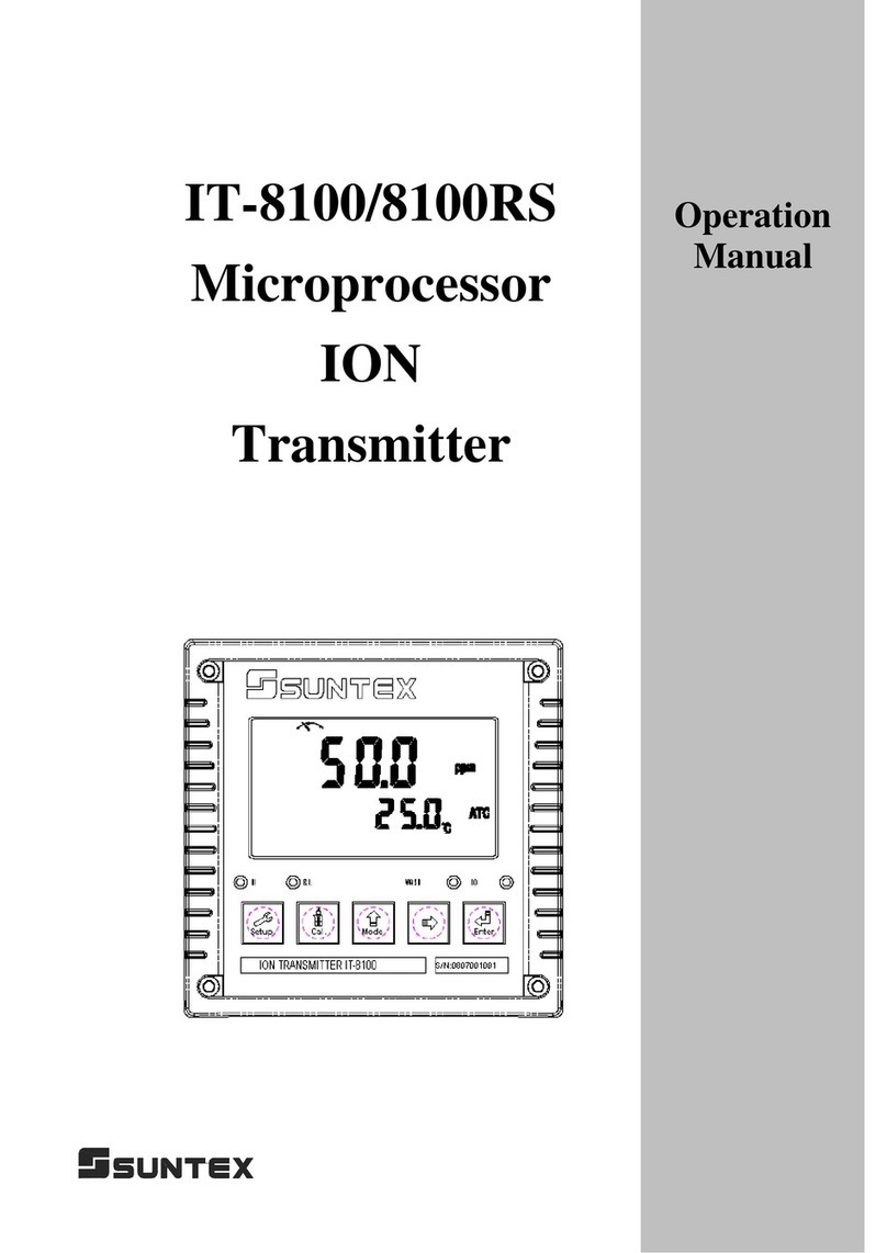
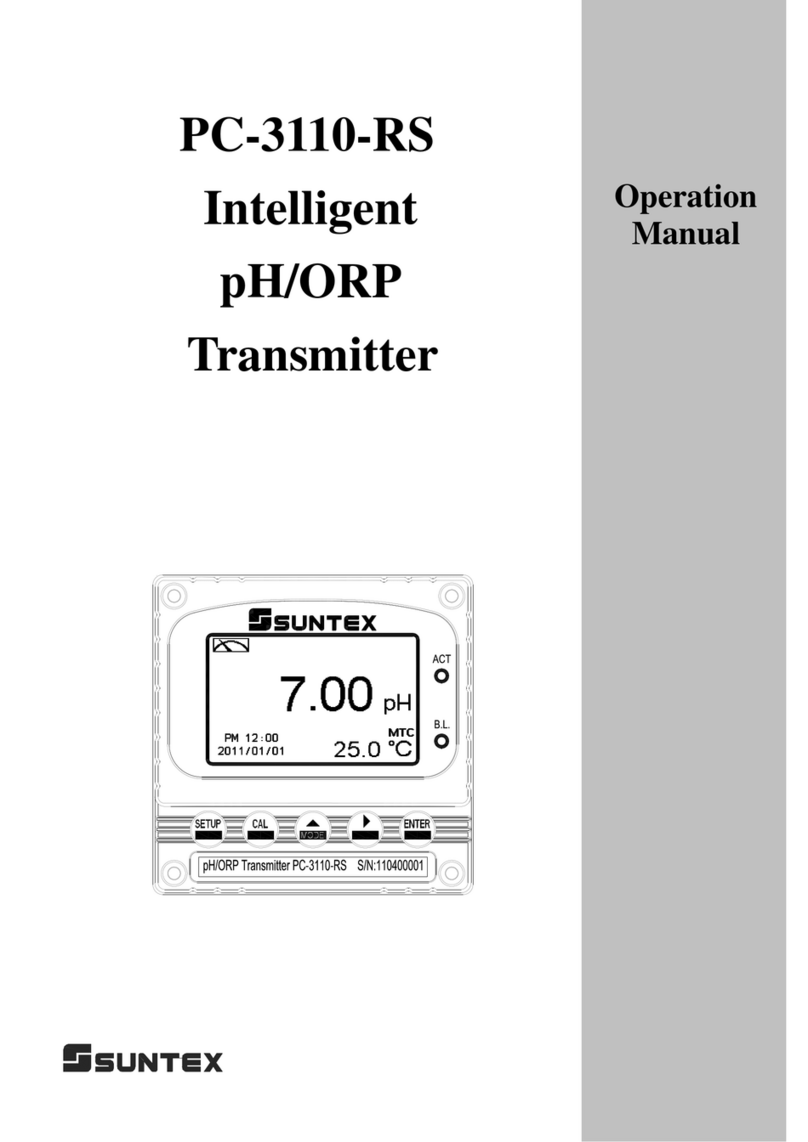
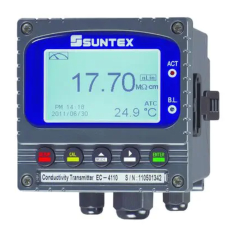
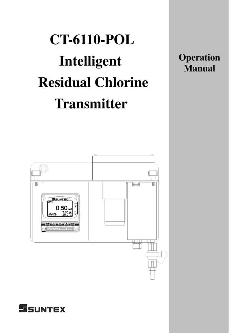
Suntex PC-3310 Installation manual

PC-3310
Intelligent
ġ
ġġ ġ ġ
pH/ORP
Transmitter
Operation
Manual

Precautions for installation
Brief Instruction
1.Specification
2.Assembly and installation
2.1 Transmitter installation................................................................................................................ 5
2.2 Illustration of panel mounting...................................................................................................... 5
2.3 Illustration of wall mounting and pipe mounting ........................................................................ 6
2.4 Assembly of electrode and housing ............................................................................................. 7
2.4.1 Cable set-up .......................................................................................................................... 7
2.4.2 Assembly of immersive electrode holder and junction box 8-09-5+ PP-100A(Optional) ... 7
2.5 Illustration and description of junction box................................................................................. 9
3. Overview of pH transmitterPC-3310
3.1 Illustration of rear panel:............................................................................................................ 10
3.2 Illustration of terminal function:................................................................................................ 10
3.3 Description of terminal function.................................................................................................11
3.4 Installation of accessorial transmitter PH-300T (Optional)....................................................... 12
3.5 Connection of transmitter PC-3310 and accessorial transmitter PH-300T................................ 13
3.6 Typical wirings........................................................................................................................... 14
3.7 Illustration of electrical connection ........................................................................................... 15
3.8 Online pH/ORP measurement system˄Optional˅.................................................................. 16
4. Configuration
4.1 Illustration of front panel:.......................................................................................................... 17
4.2 Keypad:...................................................................................................................................... 17
4.3 LED indicators:.......................................................................................................................... 17
4.4 Display:...................................................................................................................................... 18
5. Operation
5.1 Measurement mode:................................................................................................................... 19
5.2 Set-up menu:.............................................................................................................................. 19
5.3 Calibration menu: ...................................................................................................................... 19
5.5.1 Setting default value: .......................................................................................................... 19
6. Settings
6.2 Security code of settings............................................................................................................ 24
6.3 Language.................................................................................................................................... 25
CONTENTS

6.4 Mode.......................................................................................................................................... 26
6.5 Multi-Cal.................................................................................................................................... 27
6.6 Temperature ............................................................................................................................... 28
6.7 Relay 1 ....................................................................................................................................... 29
6.8 Relay 2 ....................................................................................................................................... 30
6.9 Clean.......................................................................................................................................... 31
6.10 Analog output 1 (pH/ORP) ...................................................................................................... 32
6.11 Analog output 2 (Temperature)................................................................................................ 33
6.13 Sample average of measurements (Digital Filter) ................................................................... 35
6.14 Backlight settings..................................................................................................................... 36
6.15 Contrast settings....................................................................................................................... 37
6.16 Return....................................................................................................................................... 38
7. Calibration
7.1 Enter calibration setup menu ..................................................................................................... 40
7.2 Security password of calibration (Code).................................................................................... 41
7.3 pH Calibration............................................................................................................................ 42
7.3.1 TECH Buffers mode........................................................................................................... 42
7.3.2 NIST Buffers mode............................................................................................................. 42
7.3.3 Any Buffers mode............................................................................................................... 42
7.3.4 Definition of calibration parameter..................................................................................... 43
7.3.5 TECH, NIST buffer Calibration.......................................................................................... 44
7.3.6 Any Calibration................................................................................................................... 45
7.4 ORP Calibration......................................................................................................................... 46
7.5 Return......................................................................................................................................... 47
8. Error messages (Error code)
9. Maintenance
Appendix

Thank you for purchasing Suntex products. In order to continually improve and enhance the transmitter’s function,
Suntex reserves the right to modify the content and icon display of the product. The actual situation is subject to
the instrument without notice. The operation manual is only provided for function and installation description,
Suntex Instruments Co., Ltd. is not liable for any person or entity for any direct or indirect loss or damage due to
improper usage of this product. If you have any questions or find omission, negligence or mistakes of the
operation manual, please contact with our staff, thank you.
Precautions for installation
Wrong wiring will lead to breakdown or electrical shock of the instrument, please read this
operation manual clearly before installation.
zMake sure to remove AC power from the transmitter before wiring input, output connections,
and remove it before opening the transmitter’s housing.
zThe installation site of the transmitter should be good in ventilation and avoid direct sunshine.
zThe material of signal cable should be special coaxial cable. Strongly recommend using our
coaxial cable. Do not use normal wires instead.
zAvoid electrical surge when using power. Especially when using three-phase power, use
ground wire correctly. If the power surges interference occurs, separate the power supply of
transmitter from the control device, such as: dosing machines, mixers, etc. to make individual
power supply for the transmitter; or set surge absorber to reduce the power surges at all
electromagnetic switches and power control device coils.
zThe internal relay contact of the instruments is for alarm or control function. Due to safety,
please must connect to external relays which can stand enough ampere to make sure the
safety operation of the instrument.炷
炷
Please refer to chapter 3.7“Illustration of electrical
connection”
炸
zThere shows LABEL on the display any time, so there are not showing the graphic menu of
function descriptions in this operation manual.
!
!
!
!
!
!
!
!
!

Brief Instruction
Description of set-up settings炷see chapter 6 for details炸
press and simultaneously to see the overview of the set-up settings now. Then press
if you would like to modify set-up settings. Press keypad according to index of keypad on the screen.
Index of keypad烉
烉
keypad Accordingly item Description
Back to upper layer
Choose leftward of change to left page
Increase digit
Choose rightward of change to right page
Decrease digit
Confirm settings after modifications and then go through
next step
Selection of set-up items
烉
keypad Accordingly item Description
Mode Measurement mode, to choose pH or ORP measurement
Multi-Cal.
Multi-point calibration, to choose 1, 2, or 3 points
calibration (PC-3310 provides up to three points
calibration)
Temperature
Temperature measurement and compensation, including
MTC, PTC, NTC (3 types total). MTC---Manual
temperature compensation, PTC/NTC--- auto temperature
compensation
Relay 1 First relay setting, to choose action off or Hi/Lo alarm
Relay 2 Second relay setting, to choose action off or Hi/Lo alarm
к

Clean Automatic wash time setting, to choose electrode clean
equipment’s ON and OFF duration
Analog 1 Current output according to pH or ORP setting range
Analog 2 Current output according to temperature setting range
Clock
Clock setting (When out of power and reboot it, the
instrument’s time setting will return to the factory
pre-setting)
Digital Filter Take every serial 1~60 measurements, average them
continuously, and make it as the readings
Back Light Backlight setting, to set Auto/ON/OFF backlight,
brightness, and sensitivity
Contrast Contrast of screen setting
Return Setting of returning to the measurement mode
Code
Security code of set-up mode. The set-up code is
precedential to calibration code, thus it can pass a different
security code of calibration.
Language Available for English, Traditional Chinese, Simplified
Chinese
л

Description of calibration settings炷see chapter 7 for details炸
Press and simultaneously to see the last calibration information. Then press if you
would like to make a new calibration or modify setting of calibration. Press keypad according to
index of keypad on the screen.
Index of keypad烉
keypad Accordingly item Description
back to upper layer
Choose leftward of change to left page
Increase digit
Choose rightward of change to right page
Decrease digit
Confirm settings after modifications and then go through
next step
Selection of calibration settings
keypad Accordingly item Description
TECH Use TECH buffer as standard solution for calibration
NIST Use NIST standard buffer (DIN 19266) as standard
solution for calibration
Any Use any buffer solution by users’ definition for calibration
Return Time interval setting of returning to the measurement
mode
Code Security code of calibration mode.
м

1.Specification
Model PC-3310
Measurement modes pH/ORP/Temp
Ranges
pH -2.00~16.00pH
ORP -1999~1999mV
TEMP -30.0~130.0ɗ
Resolutions
pH 0.01pH
ORP 1mV
TEMP 0.1ɗ
Accuracy
pH ±0.01pH (±1 Digit)
ORP ±0.1% (±1 Digit)
TEMP ±0.2ɗ(±1 Digit)
Equipped with temperature error modification function
Temperature
Compensation
NTC30K / PT1K auto temperature compensation
Manual adjustment temperature compensation
Calibration mode TECHİġNISTİġAny Buffersup to three point calibration
Ambient Temp. 0~50ɗ
Storage Temp. -20~70ɗ
Input Impedance > 1012 ȍ
Display Large LCM with sensitization sensor for auto/manual illumination
function & contrast function.
Language Available for English, Traditional Chinese, Simplified Chinese
Analog output 1 Isolated 0/4~20mAcorresponding to main measurement,
max. load ȍ
Analog output 2 Isolated 0/4~20mA corresponding to Temp., max. load 50ȍ
Settings Contact RELAY ON/OFF contact, 240VAC 0.5A Max.(recommended)
Activate Hi/Lo. Hi/Hi/. Lo/Lo selectable two limited programmable, ON/OFF
Wash RELAY contact, ON 0~99min. 59sec./ OFF 0~999hr 59min.
Voltage output DC±12V炻1W Max. for PH-300T(Optional)
Protection IP65
Power supply 100V~240VAC±10%炻6W Max.炻50/60Hz
Installation Wall / Pipe / Panel Mounting
Dimensions 144mm × 144mm × 115mm (H×W×D)
Cut off Dimensions 138 mm × 138 mm (HuW)
Weight 0.8 Kg
н

2.Assembly and installation
2.1 Transmitter installation
This transmitter can be installed through panel mounting, wall mounting and 2ȿpipe mounting.
Installation of panel mounting: First, prepare a square hole of 138mm x 138mm on the panel box,
and then insert the controller directly into the panel box. Insert the accessorial mounting bracket
from the rear, and make it be fixed into pickup groove.
2.2 Illustration of panel mounting
ġ
91 mm
138 mm
138 mm
Hole size
42 mm
為
42 mm
為
為
為
Mounting bracket
Hole distances on the panel box
Illustration of panel mounting,
fixed with mounting bracket
о

2.3 Illustration of wall mounting and pipe mounting
Installation of pipe mounting,
Fixed with U-shaped pipe clamp.
Optional, Order Number烉8-34ġġ
Installation of wall mounting.
Fixed with 4 x M5 screws.
Sun shield (Pipe mounting, Optional)
Order NO烉8-35為8-35-1
Sun shield (Wall mounting, Optional)
Order NO烉8-35為8-35-2
Penetrate the two prepared holes in the rear cover and fix
the U-shaped pipe clip. In order to prevent from the
water vapor, install two waterproof squeezed caps into
the holes from inner rear cover.
Insert the single hole rubber plug into the
unused cable gland, and then tighten up
the cable gland to prevent from the
penetration of water vapor.
п

2.4Assembly of electrode and housing
2.4.1 Cable set-up
a. Make sure to remove the conductive rubber or aluminum-foil layer between the electrode signal
wire and the coaxial shield.
b. Extend the cable to the transmitter without any joint except specific junction box. Connect the
transparent coaxial inner directly to the Glass terminal on the back of transmitter, and metal
connect coaxial shield to Refįterminal.
2.4.2Assembly of immersive electrode holder and junction box 8-09-5+ PP-100A(Optional)
1. Insert the electrode(H) through PP Electrode Protective Housing(G)
2. Rinse the electrode(H) properly, so that it can be easily pass through Rubber electrode holder(I)ĭ
leave about 5cm bellow.
3. Install the prepared Rubber electrode holder (I) into PP Electrode Protective Holder(G) and fix
with PP pipe protective cover(J) tightly.
A------ Upper cover of round junction box
B------ O-ring
C------ Cable fixing gland MG16A
D------ Lower cover of round junction box
E------ Cable fixing point MG16A
F------ O-ring
G------ PP Electrode Protective Housing
H------ Electrode (SensorĪ
I------- Rubber electrode holder
J------- PP pipe protective cover
Set-up diagram of coaxial cable:
See the correct set-up method on the left:
Note: The black conductive rubber
covering on the coaxial inner should be
removed.
Metal coaxial shield
Transparent coaxial inner
(Remove the conductive rubber)
р

4. Insert the Electrode cable(H) through Lower cover of round junction box(D) and Cable fixing
gland(C), and use Lower cover of round junction box(D) to fix PP Electrode Protective
Housing(G) tightly.
5. Prepare 15cm cable in the PP pipe, and then fix Cable fixing gland MG16A(C) tightly. Leave
Electrode cable(H) for about 12-14cm, and split it carefully.
6. Fix the terminal of electrode coaxial inner on terminal block 1 of round holder; Fix the terminal
of electrode coaxial shield on terminal block 3. (See the instruction of junction box)
7. Extend the cable to pass through Cable fixing gland(E) on Lower cover of round junction
box(D), and fix Cable fixing gland MG16A(E) tightly, leaving 12-14cm in the box for split.
8. Extend the lead coaxial inner and electrode coaxial inner to connect them; extend the lead
coaxial shield to fix on the terminal block 3. Tight up Upper cover of round junction box(A) to
finish the installation.
Installation of holder support base
The L-shaped electrode holder support base is installed by finding a appropriate position in the
edge of a pool according to the field’s needs with nails or expansion screws.
1. Fix the holder fixed plate(C) into the support base (D)
2. Fix the U-shaped clamp (A) into immersive holder (B)
3. Combine the item 1. and item 2., tighten it up by the plastic screws (E)
A------Holder U-shaped clamp
B------Immersive holder(PP-100A)
C------Holder fixed plate
D------Support base
E------Plastic screws
с

2.5 Illustration and description of junction box
(Two-wire distributing system
and Three-wire distributing system)
(1) Two-wire distributing system
INPUT terminals Terminal
No. OUTPUT terminals Terminals on
Transmitter
Coaxial inner 1 Coaxial inner’s extension wire for
electrode GLASS
Shield (forbidden) 2 Shield (forbidden) ------
Coaxial shield 3 Coaxial shield’s extension wire for
electrode REF
Temperature probe
red wire 4 Red wire’s extension wire for
electrode T/P
Temperature probe
green wire 5 Green wire’s extension wire for
electrode SG
Alternative 6, 7 Alternative ------
Note: 1. Extension cable, Order number: 7202-F94009-BK or 7202-RG-58
1.) If temperature probe is not used, the Order No. is 7202-RG-58.
2.) If temperature probe is used, the Order No. is 7202-F94009-BK.
2. If temperatures probe 8-26-3(NTC30K) or 8-26-8(PT1000) is used for two-wire distribution, the
black wire terminal should be forbidden.
(2) Three-wire distributing system
IN terminals Terminal
No. OUT terminals Terminals on
Transmitter
Coaxial inner 1 Coaxial inner’s extension wire for
electrode GLASS
Solution ground wire
(Shield) 2 Solution ground wire SG
Coaxial Shield 3 Coaxial Shield’s extension wire for
electrode REF
Temperature probe
red wire 4 Red wire’s extension wire for
electrode T/P
Temperature probe
green wire 5 Green wire’s extension wire for
electrode SG
Alternative 6, 7 Alternative ----
Note: 1. The black wire on the temperature probes of 8-26-3(NTC30K) or 8-26-8(PT-1000) is used as special
wire as solution ground rod which is to be connected at terminal 2.
2. The extension cable, Order Number: 7202-F94009-BK, is for system that apply a temperature probe or
solution ground rod.
т

3.OverviewofpHtransmitterPC-3310
3.1 Illustration of rear panel:
3.2 Illustration of terminal function:
POWER
WASH/Cln
2
4/20m
A
為
炼
Ʋ12V
為
炼
REL2REL1
AC
INPUT
POWER
1
4/20m
A
為
炼
Temp
(T/P Shield)
SG
T/P
GLASS
REF
pH/
ORP
кй

3.3 Description of terminal function
烀
烀
100~240AC烉
烉
Power supply terminal
烁
ġ
ġ
烂
WASH
烉
Wash relay contact for an external relay
烃
烄
REL2
烉
Second alarm control, the contact for an external relay
烅
ġ
ġ
烆
REL1
烉
First alarm control, the contact for an external relay
烇
烈
NC / D-(A)烉
烉
None contact
烀炿
4~20mA-terminal / G烉
烉
Temperature current output terminal -, for external
recorder or PLC control
烀烀
4~20mA+terminal / D+(B)烉
烉
Temperature current output terminal +, for
external recorder or PLC control
烀烁
4~20mA-terminal烉
烉
Master measure current output terminal -, for external
recorder or PLC control
烀烂
4~20mA+terminal烉
烉
Master measure current output terminal +, for external
recorder or PLC control
烀烃
DC
Ʋ
12V
烉
Output terminal of direct current voltage ±12V (PH-300T only)
烀烄
烀烅
T/P烉
烉
Connect with one of cable end of temperature probe
烀烆
SG烉
烉
Solution ground wire. In two-wire distributing system, there should
be a jumper between this terminal and REF (a short circuit slice is
attached when going out the factory)
烀烇
REF
烉
Coaxial shield of pH/ORP electrode signal wire
烀烈
NC烉
烉
None contact
烁炿
GLASS烉
烉
Coaxial inner of pH/ORP electrode signal wire
кк

3.4 Installation of accessorial transmitter PH-300Tġ
ġ
(Optional)
Accessorial pH/ORP transmitter, PH-300T, is mainly installed on the electrode protective pipe, but
also can apply wall mounting and pipe mounting. For long distance transmission (100m), if
PC-3110 is more than 30m far away from the electrode, PH-300T accessorial transmitter is
recommended to avoid the attenuation of electrode signal, and for the convenience of onsite
observation, measurement, and calibration.
Illustration of wall mounting type
1. Combine the sun shield and PH-300T transmitter by round stainless steel screws 4x15
2. Fix item 1 combination on wall by self-tapping screws
Illustration of pipe mounting type
1. Fix immersive holder(B) into U-shaped clamp(A)
2. Combine the item 1. combination with PH-300T(C) by Round stainless steel screws 4ǘ15
A------Sun shield of PH-300T
B------PH-300T transmitter
C------Round stainless steel screws 4x15
D------Self-tapping screws(by customers)
A------U-shaped clamp
B------Immersive holder
C------PH-300T transmitter
D------ Round stainless steel screws 4ǘ15
кл

3.5 Connection of transmitter PC-3310 and accessorial transmitter PH-300T
A. Connect the GLASS point of transmitter PH-300T’s terminal to the electrode coaxial inner.
(Note: Remove the black conductive rubber); connect the REF point of transmitter PH-300T’s
terminal to the electrode coaxial shield.
B. See the two-wire distributing system and three-wire distributing system in the following page.
C. Sign “PT-1000” on transmitter PH-300T’s terminal is the connector for automatic temperature
compensation probe, PT-1000, or applies a fixed temperature compensation resistance.
D. The V+ and V- of transmitter PH-300T’s terminal respectively connect to DC12V+ and – of the
controller.
E. The S+ and S- on transmitter PH-300T’s terminal respectively connect to GLASS and REF of
the controller.
F. The I+ and I- on transmitter PH-300T’s terminal are output (4-20mA), which can connect to
devices that receive current signals. (Note: The current output signal of this transmitter is
not insulating, and thus do not directly connect with a PLC!)
Note: Refer to the following table for proper fixed temperature compensation resistance
Temperature0ć5ć10ć15ć20ć
R value ȍ ȍ ȍ ȍ ȍ
Temperature25ć30ć35ć40ć45ć
R value ȍ ȍ ȍ ȍ ȍ
Temperature50ć55ć60ć65ć70ć
R value ȍ ȍ ȍ ȍ ȍ
Temperature75ć80ć85ć90ć100ć
R value ȍ ȍ ȍ ȍ ȍ
км

3.6 Typical wirings
Three-wire distribution
GND REF. GLAS
pH/
ORP
Coaxial
inner
Coaxial
shield
Black
Two-wire distribution
GND REF. GLAS
pH/
ORP
Coaxial
inner
Coaxial shield
Short circuit slice
кн

3.7 Illustration of electrical connection
Surge absorber
Surge absorber
Surge absorber
Surge absorber
Transmitter
Cleaning device
Dose feeder
Dose feeder
100 ~ 240VAC
Surge absorber
Surge absorber
External relay
External relay
External relay
Note: The transmitter built-in miniature relays is necessary to be repaired and replaced by professional technicians.
It is recommended to use an external relay (Power Relay) to activate the external equipments.
100V~240VAC
Relay 2Relay 1 WASH/Cln
100V~240VAC
Transmitter
ńŭŦŢůŪůŨġťŦŷŪŤŦġ
ŔŶųŨŦġŢţŴŰųţŦųġ
M
ŔŶųŨŦġŢţŴŰųţŦųġ
ņŹŵŦųůŢŭġųŦŭŢźġ
ŅŰŴŦġŧŦŦťŦųġ
ŔŶųŨŦġŢţŴŰųţŦųġ
M
ŅŰŴŦġŧŦŦťŦųġ
ŔŶųŨŦġŢţŴŰųţŦųġ
M
ŔŶųŨŦġŢţŴŰųţŦųġ
ņŹŵŦųůŢŭġųŦŭŢźġ
ŔŶųŨŦġŢţŴŰųţŦųġ
ņŹŵŦųůŢŭġųŦŭŢźġ
Note: The transmitter built-in miniature relays is necessary to be repaired and replaced by professional technicians.
It is recommended to use an external relay (Power Relay) to activate the external equipments.
ко

3.8 Online pH/ORPmeasurement system炷
炷
Optional
炸
A
B
C
D
E
F
G
A烉㰱ℍ⺷
B烉㴖≽⺷
C烉⺽㳩⺷
D烉1/2ģˣ3/4ģ䭉嶗⺷
E烉1ģ䭉嶗⺷
F烉“㍺⺷
G烉枪㍺⺷
㯜㳩㕡⎹
A烉Immersion system in open basin
B烉Measurement in very variable water levels, or lakes
with a float
C烉Flow-through system
D烉1/2” & 3/4” pipe mounted system
E烉1” pipe mounted system
F烉Side-entry system in vessel
G烉Top-entry system in closed vessel
кп
Table of contents
Other Suntex Transmitter manuals

Suntex
Suntex CT-6300RS User manual

Suntex
Suntex TC-7310-RS-M User manual

Suntex
Suntex CT-6110-POL User manual

Suntex
Suntex EC-4110-I User manual

Suntex
Suntex PC-300A Series User manual

Suntex
Suntex PC-3310-RS User manual

Suntex
Suntex CT-6300 User manual

Suntex
Suntex EC-4110 User manual

Suntex
Suntex TC-7100 User manual

Suntex
Suntex TC-7310-RS User manual
Popular Transmitter manuals by other brands

Erone
Erone SETR2641-TM Getting started

PCB Piezotronics
PCB Piezotronics IMI Sensors 682C33 Installation and operating manual

SOR
SOR echosonix U11 General instructions

WisyCom
WisyCom MTP30 Quick user guide

Siro
Siro SIS1605 manual

BURK Technology
BURK Technology PlusConnect Installation and operation manual