FLYGT APP 541 User manual
APP 541
User manual
Autamatic Pump Pilot APP 541
Reset
Esc OK


Table of Contents
Read This First.........................................................................................................................................3
Read This First......................................................................................................................................3
Shortguides.............................................................................................................................................5
Shortguides..........................................................................................................................................5
Front Panel..............................................................................................................................................8
Front Panel........................................................................................................................................... 8
Configure Basics.................................................................................................................................. 11
Configuration Startup.......................................................................................................................11
Configure I/O-module Communication.........................................................................................11
Configure Analogue Level Sensor..................................................................................................12
Start, Stop, High and Low Levels.....................................................................................................12
Configure I/O....................................................................................................................................... 14
Configure General Purpose Inputs.................................................................................................14
Other Inputs.......................................................................................................................................15
Configure Outputs............................................................................................................................16
Other Outputs................................................................................................................................... 17
Extra Options With Three Pumps or Less.......................................................................................17
Extended Configuration......................................................................................................................20
Trim Level Control.............................................................................................................................20
Configure Pump Control..................................................................................................................20
Trim Pump Control............................................................................................................................21
Configure Extra Functions................................................................................................................23
Configure Communication.................................................................................................................24
Systems...............................................................................................................................................24
Configuration.....................................................................................................................................25
Configure Alarm Handling..................................................................................................................29
About Alarms.....................................................................................................................................29
General...............................................................................................................................................29
Alarms Sent to SCADA System........................................................................................................30
Alarms Sent to SMS Receivers......................................................................................................... 30
Special Alarms................................................................................................................................... 31
Measure Flow Rate and Capacity.......................................................................................................33
Estimate Pump Capacity.................................................................................................................. 33
Estimate Overflow Flow and Volume............................................................................................. 33
Read Operational Data........................................................................................................................36
Read Operational Data.....................................................................................................................36
Monitor Status and Alarms................................................................................................................. 38
Monitor Status on Front Panel.........................................................................................................38
Monitor Alarms in the RTU...............................................................................................................40
Monitor Alarms Sent as SMS............................................................................................................41
Special Alarms................................................................................................................................... 41
Table of Contents
APP 541 User manual 1

Miscellaneous.......................................................................................................................................43
Change Between Automatic, Manual and Blocked Mode...........................................................43
Troubleshooting................................................................................................................................43
Appendix A: RTU Descriptions...........................................................................................................45
List of Alarms .....................................................................................................................................45
List of Menus .....................................................................................................................................47
Appendix B: Tag List............................................................................................................................60
Appendix B: Tag List.........................................................................................................................60
Appendix C: SCADA Systems............................................................................................................ 66
Flygt SCADA System (Aquaview) ................................................................................................... 66
Other SCADA Systems..................................................................................................................... 68
Table of Contents
2 APP 541 User manual

Read This First
Read This First
This manual is applicable to the following versions
• Hardware:APP 541
• Operator panel: AFH1801 Rev 1.02 or later
• I/O-module: AHH1801 Rev 1.02 or later
• Com-module: TMX1801 Rev 1.00 or later
• System Software: 2.73 or later
• Application: 1.44 or later
Introduction
Before starting to use APP 541, read this chapter carefully. It contains general information
on documentation, safety and guarantee.
Product Overview
APP 541 is a pump controller that consists of an I/O module and an operator panel.
APP 541 can use a PSTN, GSM, GPRS or radio modem to communicate with a SCADA
system, for example AquaView. A special communication module is available for this
purpose.
Safety rules for the owner/operator
• All government regulations, local health and safety directives must be observed.
• All danger due to electricity must be avoided.
Guarantee
• Modifications or changes to the unit/installation should be done only after consulting
Xylem.
• Genuine spare parts and accessories authorized by the manufacturer are essential for
compliance with the terms of the guarantee. The use of other parts may invalidate the
guarantee.
This manual
• In this manual, APP 541 is generally referred to as the RTU.
• In order to avoid repetition of information, the manual describes how one pump P1,
should be read or entered.
• If a second pump or more pumps, are included in the installation, these instructions
must be repeated for each additional pump.
Symbols used
NOTICE:
•
Special information about a function.
•
Information concerning the Central system.
•
Information about alarms.
Terminology
The table below describes the terms and abbreviations that are used in this manual.
Abbreviation Full Term Description
CS Central System Used in menus. The term means SCADA system.
Read This First
APP 541 User manual 3

Abbreviation Full Term Description
RTU Remote Terminal Unit Unit for supervising and controlling a pump station, for
example APP 541.
SCADA Supervisory Control And
Data Acquisition PC based system aiming to create an overview; the
operator can monitor process information and influence
and change the process values.
The system allows logging, trending and remote
commands as well as presenting process data as
significant digits, staples, curves, trends, or as symbols
varying in colors and sizes.
Read This First
4 APP 541 User manual

Shortguides
Shortguides
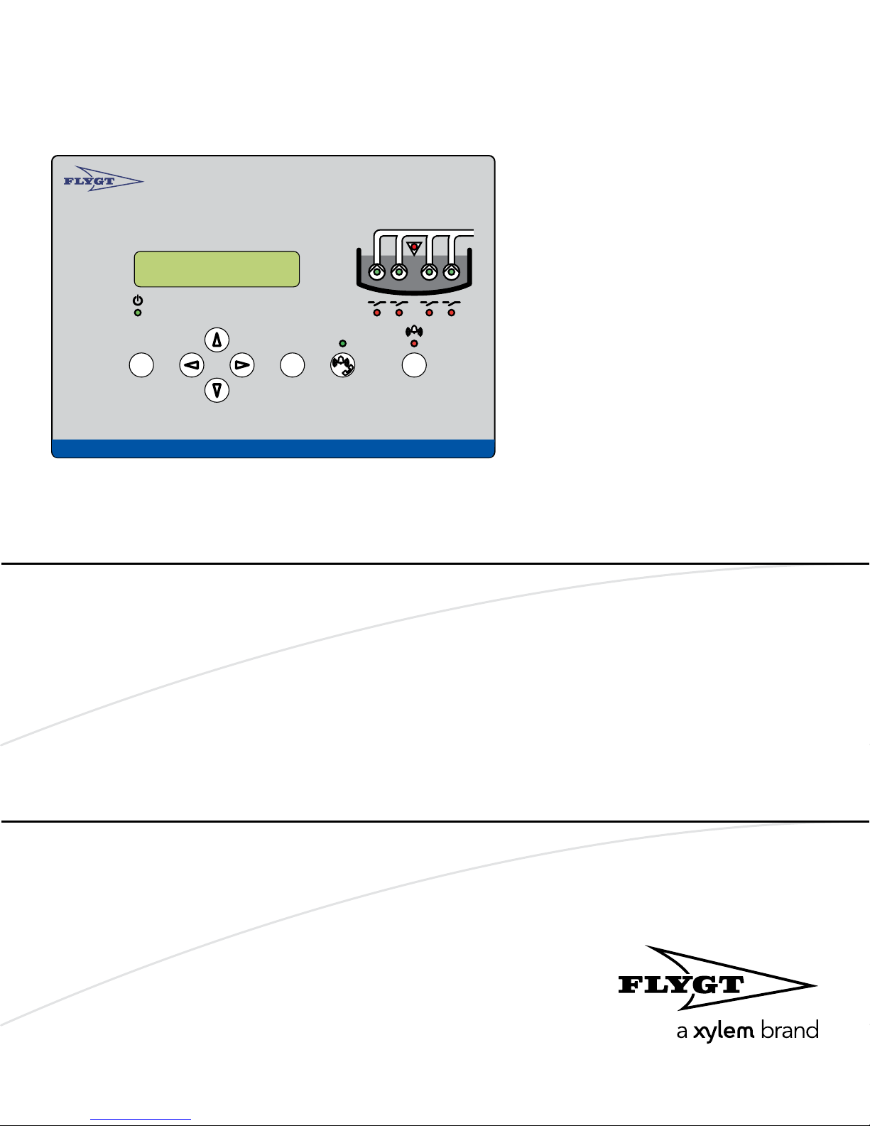
Front panel
Autamatic Pump Pilo t APP 541
Rese t
Esc OK
1
2
3
4
5
6
7
8
9
1. Display
2. Power LED
3. Push buttons
4. High level LED
5. Pump status LED
6. Relay status LED
7. Alarm status LED
8. Reset
9. Remote alarm On/Off
Push buttons
Esc
Escape:
Exit a menu without saving any changes.
Exit a sub-menu.
Up arrow:
Scroll backwards one menu at a time. Edit a
value.
Left arrow:
Go back. Move the cursor to the left, while
editing a value.
OK
OK:
Display the first menu in a sub-menu group.
Save a specified value.
Right arrow:
Advance. Move the cursor to the right, while
editing a value.
Remote alarm On/Off:
When remote is on, alarms are transmitted
to CS/SMS.
Down arrow:
Advance one menu at a time. Edit a value.
Reset
Reset:
Acknowledge a new alarm. It is not removed
from the alarm log.
View pump running hours and number of starts
1. Display the Operating data (7_) menu, and press OK.
2. Repeat for P1 Start counter (7_1), and P1 Run hour (7_2) to P4 Start counter (7_3) and
P4 Run hour (7_4) respectively.
View and delete alarms
1. Display the Alarm log (1) menu and press OK.
2. Browse the log by repeatedly pressing the Down button.
Shortguides
APP 541 User manual 5

3. Scroll to the required alarm and press OK.Result: A "Delete alarm?" message
appears and “Current” is displayed.
4. Choose between "Current" and "All" by pressing the Down button and then OK.
Result: The alarm is cleared and the text "Log cleared" message is displayed.
Change a parameter value, for example a level setpoint
1. Display the Level (2_) menu and press OK.
2. Select the menu you want to change (Start / Stop level 1–4 or High / Low level). Press
OK.
3. Select a new parameter value or alternative. Press OK.
Show installation and service menus
To show menus that are used only during installation or service, select “Yes” in the Show
more menus menu (18). The backlight is switched off when the display has been idle for
ten minutes.
Menu reference chart
Legend (Flygt default settings):
Always shown:
Normally hidden:
Shown depending on configuration:
Shortguides
6 APP 541 User manual
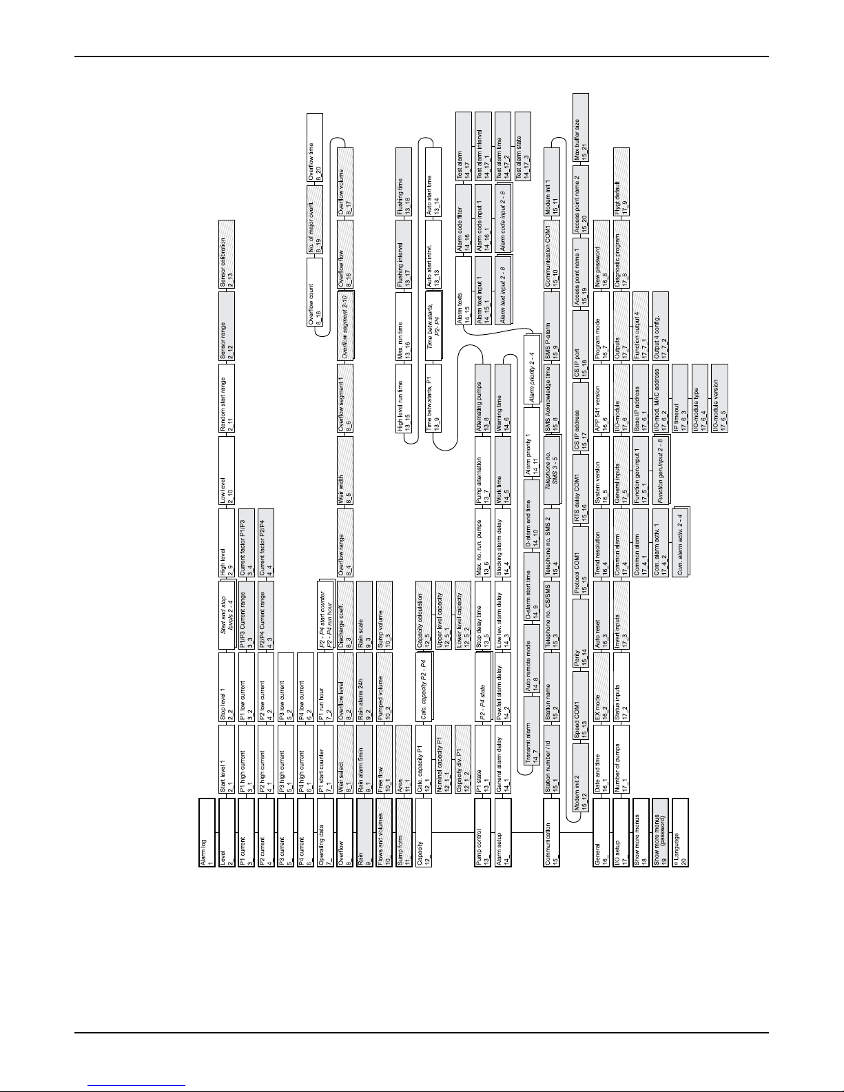
(Reference: For a detailed menu list, refer to Appendix A).
Shortguides
APP 541 User manual 7

Front Panel
Front Panel
Illustration: Front panel
Autamatic Pump Pilo t APP 541
Rese t
Esc OK
LEDs on front panel
Power LED High level LED
Communication status LED Pump status LED
Alarm status LED Relay status LED
(Reference: “Monitor Status on Front Panel” for an explanation of LED functions).
Push buttons on front panel
The push buttons are used to browse menus, and edit parameter values. Each menu has
an indicator, for example "20".
• The indicator is shown for 3 seconds only.
• An underscore after the last number indicates a submenu, for example "2_".
(Reference: “List of Menus” for a complete list of menus).
Viewing a menu
Use the Up arrow to scroll backwards one menu at a time.
Use Down arrow to advance one menu at a time.
OK
Press OK to display the first menu in a submenu group.
Front Panel
8 APP 541 User manual
Table of contents
Other FLYGT Control Unit manuals


Popular Control Unit manuals by other brands

Festo
Festo Compact Performance CP-FB6-E Brief description

Elo TouchSystems
Elo TouchSystems DMS-SA19P-EXTME Quick installation guide

JS Automation
JS Automation MPC3034A user manual

JAUDT
JAUDT SW GII 6406 Series Translation of the original operating instructions

Spektrum
Spektrum Air Module System manual

BOC Edwards
BOC Edwards Q Series instruction manual

KHADAS
KHADAS BT Magic quick start

Etherma
Etherma eNEXHO-IL Assembly and operating instructions

PMFoundations
PMFoundations Attenuverter Assembly guide

GEA
GEA VARIVENT Operating instruction

Walther Systemtechnik
Walther Systemtechnik VMS-05 Assembly instructions

Altronix
Altronix LINQ8PD Installation and programming manual


