Flytec 5030 GPS User manual
Flytec 5030GPS
Revision Date: 11/11/03

© Flytec USA, 2003
2
If you find any errors, inconsistencies or feel that some sections need better explanation, please email us at
Flytec USA would like to thank the considerable help from Davis Straub editing this manual
© Flytec USA 2003
All rights reserved.
No part of this manual may be reproduced, stored in a retrieval system, or transmitted in any form or by any means,
electronic, mechanical, photocopying, recording, or otherwise without permission in writing from Flytec USA. This
manual is protected under US and International Copyright Laws.

© Flytec USA, 2003
3

© Flytec USA, 2003
4
Introduction
Although it is possible to turn on the 5030, and go flying straight away, we recommend that you study these operating
instructions, and make yourself familiar with the various functions. We have kept the operating instructions as brief
as possible. For people who would like to freshen up on the basics, or those who want to learn more about the
individual functions and their uses, we have included in-depth explanations in the appendix (Sections E1 through
E10). These appendices are referred to in the basic instructions.
The firmware program of the 5030 is stored in ‘flash’ memory. Upgrading your unit’s firmware to the most recent
version can be done with the help of a PC, and does not necessitate sending the unit to us for service. The cable
required to connect the unit to your PC is included. To update your 5030 all you need to do is download the update
from our web site, and transfer it to your 5030 with the supplied installation software.
Please look first at the pictures of the 5030 display and keypad (Figure 1), and then study the descriptions so that
after scanning the index briefly, you will have an overview of the 5030’s functions. Note that starting with firmware
version 2.14 there are two possible configurations for the analog (upper) section of the display. The vertical bar
display is shown in figure 1 and the dial display can be seen in picture on the cover page of this manual.
We have included two ‘soft’ keys on the 5030. These are the F1 and F2 keys and their function depends on the
display mode. For example, in the Route Mode, F1 means “previous WP” and F2 “next WP”. However, when
creating a route, F1 stands for “Insert WP” and F2 “Delete WP”. In each case the meaning of the keys is shown on
the display just above the key.
The 5030 has a simulation mode that helps you better understand the numerous possibilities that the 5030 offers as
well as the theory of gliding flight. With this feature you can simulate almost any situation encountered during flight.
The user can change many settings, from descent and ascent, to airspeed or groundspeed as well as the flight
direction. He/She can also observe the effects of these on best glide speed, the McCready Indicator, arrival altitude
at destination, and distance from the destination, etc. The sounds are simulated, as well.
As with any electrical unit, you should protect your 5030 from excessive heat, hard impacts, dirt and moisture. To
ensure the best possible performance, try and keep the instrument as far away as possible from your radio antenna.
Turning the Unit On and Off
To switch it on, press and hold the ESC key for one second. The unit will then display “really switch on ?? Press
ENTER to confirm.” Confirm by pressing the Enter key. To switch off the 5030, press and hold the ESC key for three
seconds. The unit will then display “really switch off ?? Press ENTER to confirm.” Confirm by pressing the Enter
key. After a long flight with short recording intervals the calculation of the digital signature can take up to one or two
minutes. Please wait until this process is finished. Press the ESC key again to turn off the unit.
Setup Menu
You may configure the 5030 to your preferences using Basic Settings in the Setup Menu. Press and hold the Menu
key until the Main Setup Menu appears. Basic Settings will be highlighted, press the Enter key to enter the Basic
Settings menu. There are multiple pages of menu items. Use the and arrow keys to move the highlight one
item up or down. Use the or arrow keys to page through the Basic Settings Menu.

© Flytec USA, 2003
5
Table of Contents
Introduction
......................................................................................................................................................................
4
Turning the Unit On and Off
........................................................................................................................
4
Setup Menu
.................................................................................................................................................
4
Technical Data
................................................................................................................................................................
7
A1 Analog Vario
..............................................................................................................................................................
7
A2 Altimeter and Air Pressure
........................................................................................................................................
8
A3 Digital Vario and Netto Vario
.....................................................................................................................................
8
A4 Speed
.........................................................................................................................................................................
8
A5 Stall Alarm
..................................................................................................................................................................
9
A6 Sounds and Volume Level
........................................................................................................................................
9
A7 User-selectable fields
..............................................................................................................................................
10
A7.1 Temperature
..........................................................................................................................................
10
A7.2 Time and Date
.......................................................................................................................................
10
A7.3 Flight time
..............................................................................................................................................
11
A7.4 Track and Bearing
.................................................................................................................................
11
A7.5 Distance to Waypoint
............................................................................................................................
11
A7.6 Glide Ratio (L/D Ratio)
..........................................................................................................................
11
A8 Best Glide Speed
.....................................................................................................................................................
11
A9 Average Thermal Climb Indicator
...........................................................................................................................
11
Al0 McCready
................................................................................................................................................................
11
A11 Battery Management
.............................................................................................................................................
12
B GPS Functions
...........................................................................................................................................................
13
B1 Assessment of Reception Quality
...........................................................................................................................
13
B2 Compass and Flight Direction
.................................................................................................................................
14
B3 Speed over Ground
.................................................................................................................................................
14
B4 Head, Cross and Tail Winds, the Wind Component
...............................................................................................
14
B5 Wind Direction and Speed
.......................................................................................................................................
14
B6 Waypoints and Coordinates
....................................................................................................................................
14
B6.1 Current Coordinate Indicator
.................................................................................................................
15
B6.2 Saving the Current Position
..................................................................................................................
15
B7 Goto Function
..........................................................................................................................................................
15
B8 Flying Routes
...........................................................................................................................................................
16
B8.1 Direction arrow to second next waypoint:
.............................................................................................
16
B9 The FAI Route for Record Flights and Competition Pilots
.....................................................................................
16
B9.1 Changing a route into the FAI Route:
..............................................................................................
16
B10 Relocating Thermals
..............................................................................................................................................
18
C 5030’s Setup Menu (Set-up Mode)
..........................................................................................................................
18
C1 Basic Settings
..........................................................................................................................................................
19
C2 Flight Memory and Flight Analysis
..........................................................................................................................
20
C2.1 Graphic Display of Flights in Map Format
............................................................................................
20
C3 Waypoints - Edit, Delete, or Add
.............................................................................................................................
21
Editing Waypoints:
.........................................................................................................................................
21
Deleting Waypoints:
.......................................................................................................................................
22
Inserting Waypoints:
.......................................................................................................................................
22
C4 Routes - Create, Alter, Delete
.................................................................................................................................
22
Creating a New Route
....................................................................................................................................
22
Altering a Route:
............................................................................................................................................
23
Deleting a Route:
...........................................................................................................................................
23
C5 FAI Route - Create, Alter, Delete
............................................................................................................................
23
C6 Simulation mode
......................................................................................................................................................
23
C7 Factory Settings, Instrument Specific Parameters
.................................................................................................
24
D Data Transfer
.............................................................................................................................................................
24
D1 Data Exchange Via PC
...........................................................................................................................................
24
D2 Data Exchange via Infrared Interface
.....................................................................................................................
25
D3 Transferring New Firmware to the 5030
.................................................................................................................
25
E1 Stall alarm
................................................................................................................................................................
25
E1 Stall alarm
................................................................................................................................................................
25
E2 Netto vario
................................................................................................................................................................
26
E3 True or Indicated Airspeed; TAS or lAS
..................................................................................................................
26
E4 Polar Curve and Best Glide Speed
.........................................................................................................................
27

© Flytec USA, 2003
6
E5 McCready Theory - Optimized Speed to Fly
..........................................................................................................
28
E6 Final Glide Calculation
............................................................................................................................................
29
The last thermal
..............................................................................................................................................
30
Altitude above best glide
................................................................................................................................
30
Gliding to Goal
................................................................................................................................................
30
E7 Total Energy Compensation (TEC)
.........................................................................................................................
30
E8 New Regulation for Record Flights or Decentralized Competitions
.......................................................................
31
E9 Proof of Flights - Security against Manipulation
.....................................................................................................
31
E10 Digital Signature and OLC `Registration
..............................................................................................................
31
F1 Optional Software Packages
...................................................................................................................................
31
G1 Landing in Water
.....................................................................................................................................................
31
Guarantee and liability
..................................................................................................................................................
32
© Flytec USA, 2003
7
Technical Data
Measurements: 7” x 3-3/4” x 1-9/16” (178 x95 x 40 mm)
Weight: 15 oz. (425 grams) without bracket
Electrical supply: Nickel metal hydride accumulator 4.5 Ah; 3.6V
Battery life: > 20 hrs
Altimeter: Maximum 26,000’ (8,000 m) in 3 ft. (1 m) increments
Analogue variometer: +/- 2,000 ft/min. (10 m/s); in 20 ft/min. (0.1m/s) increments
Digital variometer: +/- 14,000 ft/min. (+/-70m/s); in 10 ft/min. (0.1m/s) increments
Speed (pitot pressure): Analogue: 19-70 mph (30 -110 km/h) in 1 mph increments
Digital: 19-94 mph (30-150 km/h) in 1 mph increments
Speed (vane wheel): Analogue: 19-70 mph (30 -110 km/h) in 1 mph increments
Digital: 0- 94 mph (0-150 km/h) in 1 mph increments
Waypoints: 200 WP
Routes: 20 routes with max. 30 WP’s in each
Maximum memory time: 110 hours flying time at 20 sec intervals
Track log points: 24 000
Number of Flights: 100
Screen resolution: 320 x 240 pixel (1/4 VGA)
Operating temperature: 5-114°F (-15...45°C)
Data & memory transfer: According to the IGC format
Brackets for hang gliders and paragliders are available.
The technical details may be altered without notification. Software upgrades are possible by downloading the latest
firmware version from our homepage.
A1 Analog Vario
The most important instrument for any kind of glider flying, after
the pilot’s brain, is the vario. The 5030 displays vertical speed
in fpm or m/sec. and informs the pilot whether he/she is
climbing or sinking. It is by using the vario, and its
accompanying sounds, that pilots can discover the most
efficient climb, or recognize when they are in rapidly
descending air.
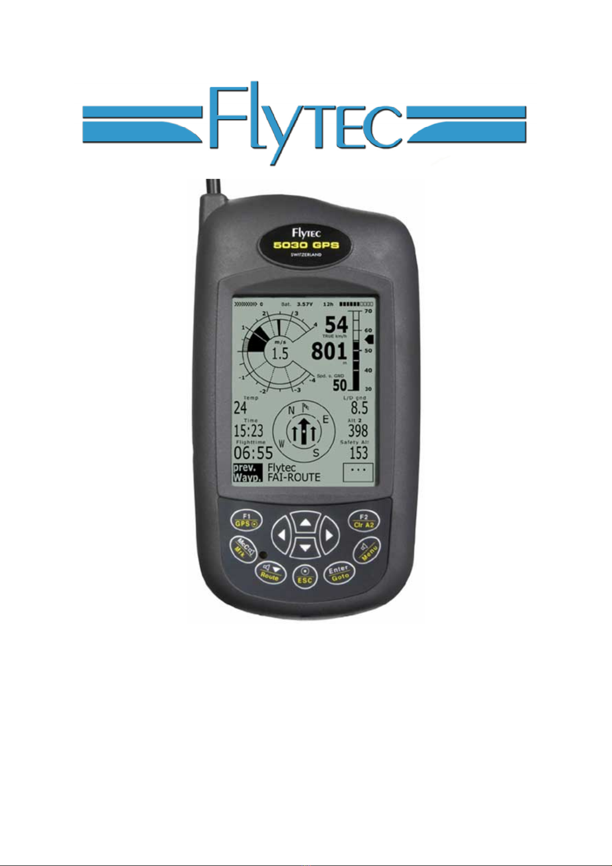
There are two possible analog vario scales on the 5030, the
dial scale shown on the front cover of the manual and the
vertical bar scale shown in the figure to the right. The scale of
either analogue vario display is 200 fpm (or 1 m/s). The
resolution of the digital vario is 10 fpm (0.1 m/s). The type of
scale dial or vertical can be selected in Menu/Basic Settings/variodisplay.
The first full-scale range is from +/-800 fpm (+/-4 m/s) after
which the display switches automatically to a second range
from 800 to 1600 fpm (4 to 8 m/s). The time interval over
which the measured climb rates are averaged (damping) for
the analogue display and associated sounds is factory set at
1.2 seconds. This can be changed to any value between 0.6
sec and 4 sec. in Menu/Basic Settings/Vario-Speed-
Average.If the time interval is too short, the vario is very
twitchy and if it is too long, it’s rather sluggish. A lower
dampening value is preferable for smooth light conditions. A
greater dampening value may be desirable in rough turbulent
conditions. Note: This setting should not be confused with
vario integration (averager) that can be set for the digital vario
display.
If the pilot is flying too fast while thermalling and compromising climb rate the 5030 will provide a visual indication on
the dial display. A radial line will appear above the indicated climb rate. To maximize climb the pilot should reduce

© Flytec USA, 2003
8
his/her speed until the radial line converges with the indicated climb rate (unless of course conditions dictate a higher
thermalling speed).
A2 Altimeter and Air Pressure
The 5030 tracks and can display three different altitudes:
A1 is the altitude above sea level (QNH).
A2 is altitude with respect to a reference height. It can be zeroed at any time by pressing and holding the F2 key.
A3 is the total height gained during a flight. If several pilots complete the same flight task, then the one who climbed
the least overall would have flown most efficiently.
Altimeter A1 should be adjusted to display the actual height above sea level (QNH). The QNH is originally set at the
factory to a sea level pressure of 29.92 inHg (1013hPa). Since it is seldom the case that you are taking off from sea
level and the air pressure is also 29.92 inHg, the correct altitude should be set before commencing each flight by
using the arrow keys (increases altitude, decreases altitude). When you adjust A1, the sea level air pressure
display also changes. The air pressure display (QNH) always refers to sea level.
The user can determine the altitude of his/her current location by setting the current sea level air pressure (QNH)
obtained from a weather radio or flight service in the Basic Settings menu (Menu/Basic Setting/QNH). If both of the
and arrow keys are pressed at the same time and the GPS is acquired the 5030 will set the GPS height to A1.
If there is no GPS reception, the unit will set the height A1 to a value that corresponds to the default QNH pressure of
29.92 inHg (1013hPa).
If A1 is set to zero for any planned landing area, then the height above this location will always be indicated after
starting. The associated air pressure (QFE) is the actual air pressure in hPa at this altitude, which deviates from
QNH, the pressure at sea level.
A2, A3 and QNH can be displayed in the user-selectable fields. See section A7 User-selectable fields
A3 Digital Vario and Netto Vario
The digital vario has a resolution of 10 fpm (0.1 m/s) and a very wide measuring range of +/-14,000 fpm (+/- 70 m/s),
ideal for displaying extreme vertical speeds, such as those found in skydiving and base-jumping. If desired the digital
vario can function as an averager (also called an integrated vario). If the dial display (see cover of this manual) has
been selected the digital vario display is in the center of the dial. The period over which the instantaneous values are
averaged can be between 1 and 30 seconds. This is very useful for determining the actual strength of a rough
thermal. The digital vario can also serve as a netto (air-mass) vario, which shows the vertical motion of the
surrounding air. Additionally, it is possible to set the digital vario to serve as an averager during climbing and as a
Netto (air mass vario) during gliding. (Menu/Basic Settings/Variomode). To find out more read section E2 Netto
Vario.
A4 Speed
After vertical speed and altitude, airspeed is next most significant piece of information. Increased safety is not the
only advantage to having an ASI (Air Speed Indicator). It also increases performance during distance flights. The
best glide speed, the McCready speed to fly, as well as the Netto Vario can function only when the airspeed is
known. The 5030 displays both digital and analog air speed and the user can choose whether he/she wants to view
air speed as a True or Indicated in the Set-Up Menu (Menu/Basic Settings/Speed mode). There are two possible
speed ranges for the analog speed display ranges (19-68 mph or 12-62mph) and can be set in Menu/Basic
Settings/Speed mode
The 5030 has two independent speed sensor connections.
1. For paragliding the optional vane wheel sensor can be used. The advantage of this sensor is that it
shows the true air speed (TAS) and begins to make correct measurements above 1 mph (1 km/h). It is
also well suited in determining the wind speed at take-off.

© Flytec USA, 2003
9
2. For hang glider pilots there is a built-in pitot pressure indicator, which measures the indicated airspeed
(IAS) and is capable of showing speeds of up to 94 mph (150 km/h) on the digital display and 19-68
mph on the analog speed scale. However, this sensor only begins to work at 19 mph (30 km/h). If
necessary, the pitot tube can be extended with a flexible hose to a turbulence-free spot on the glider.
For caged gliders an optional hang gliding vane wheel sensor can also be plugged into the port on the
left side of the unit.
It does not matter which sensor is used since both speeds (TAS and IAS) are always internally calculated. Should
you be unfamiliar with the difference in these concepts, please refer to: E3 True or Indicated Airspeed in the
appendix. Both speed sensors can be adjusted with a correction factor (Menu/Basics Settings/Speed gain vane
wheel or pressure). The factory setting is 100% for both sensor options.
A5 Stall Alarm
The stall alarm threshold, the air speed below which the stall alarm will sound, can be adjusted in the Set-Up Menu
(Menu/Basic Settings/Stallspeed). An altitude threshold, the altitude below which the stall alarm feature will be
active, can also be set in this menu. To disable the stall alarm set the air speed value to 0 mph (km/h). The trigger
point for the stall alarm is always linked to the indicated airspeed. At greater altitudes, i.e. in thinner air, the alarm
will sound earlier (i.e. at a higher flying speed) than at sea level. (Please refer to: E1 Stall Alarm in the appendix).
A6 Sounds and Volume Level
Each time the key /Menu is pressed briefly the volume level is increased by 25%. The adjustable sound levels are: 0
- 25% - 50% - 75% - 100%. The value of the chosen volume level is displayed in the status line. All of the sound
effects described in this section can be heard in the simulation mode.
Automatic volume control: The basic sound levels of 25%, 50%, and 75% will slowly increase automatically once
the airspeed exceeds 25 mph (40 km/h) but never greater than 100%.
Ascent Tone: The ascent tone starts when the climb rate exceeds a predetermined threshold. The ascent tone
threshold (the lift value that must be exceeded to start the ascent tone) can be changed in Menu/Basic
Settings/VarioOffset. The greater the Vario Offset value the greater the lift needed to start the ascent tone. As
greater lift is encountered the frequency of the ascent tone will increase at a predetermined rate (Modulation). The
tone-pause (beep…beep…beep) ratio is 1:1. It is possible to set the frequency of the ascent tone between 600 and
1400 Hz in Menu/Basic Settings/Sound/UpBase F.
Modulation: The rate at which the pitch of the ascent tone increases as increased lift is encountered is called
modulation. The modulation of the ascent audio can be adjusted to values from two to nine under Menu/Basic
Settings/Sound/modul. The higher the value, the faster the frequency will increase as the lift values increase. A
modulation setting of nine will yield more audible change at lower climb rates making it best suited for use in mild lift.
Conversely, a modulation of two will yield more audible change at higher climb rates, which will be better suited for
strong lift flying. The factory setting is five.
Pitch: By altering the pitch value (between 1 and 7) the user can customize the beep/pause length. A pitch setting of
one will yield a longer beep with a longer pause between beeps while a setting of seven will yield a shorter beep with
a shorter pause between beeps. The pitch value may be set under Menu/Basic Settings/Sound/Pitch.
Sink tone: The sink tone (alarm) is continuous and decreases in frequency as the sink rate increases and increases
in frequency as the sink rate decreases. The sink alarm can be toggled on and off by briefly pressing the /Route
key. When the sink alarm is turned on, the 5030 will sound a sample tone and the analog vario display will show the
sink alarm threshold. Under Menu/Basic Settings/Sink Acoustic you can choose the threshold at which the sink
alarm will sound. The pitch of the sink alarm can be changed under Menu/Basic Settings/Sound/ DownBase F.
Acoustic Integrator: dampens irregular sound patterns during rapid vario movements (piano effect). The settings
are from 1 to 35 and the factory setting of 8 can be changed under Menu/Basic Settings/Sound/acoust. Integr.
High values result in a smoother but somewhat delayed sound pattern.
Stall alarm: is a pitch tone of medium frequency with a very fast interval rate and is always at full volume (100%). For
more details read El Stall Alarm. This sound is not adjustable.

© Flytec USA, 2003
10
McCready tone: When gliding with McCready sound activated, a tone is heard that corresponds to the McCready
speed value (speed to fly). This tone has been chosen so that it should not be confused with the normal ascent tone.
It has a tone-pause ratio of 1:4. For more detail read E5 McCready Theory. This sound is not adjustable.
The warning tone for a negative McCready Indicator value is a deeper tone with a rapid interval sequence, which
tells the pilot to fly faster immediately. This sound is not adjustable.
A7 User-selectable fields
There are a total eighteen measured values (listed below) from which the user can choose to customize the display of
the 5030. When using the vertical bar analog scale the 5030 can be configured to show either six or four user-
selectable fields. When the dial analog scale is selected the 5030 can be set to show either five or seven user fields;
four or six in the lower part of the display and one just under the altimeter 1 display. There are a total of three pages
of user fields that can be accessed by briefly pressing arrow key. To assign a user field, press the arrow key to
select the desired user field. The description of the corresponding user field will be highlighted in black above the
displayed value. To alter the selected user field use the and arrow keys to scroll through the list of eighteen
possible values. If the user field is not changed within 10 seconds the highlighting will cancel and the original data
field will remain. The number of user fields on each of the three pages can be determined in Menu/Basic
Settings/User fields. When four user-fields per page is selected the values will be displayed considerably larger
than six per page, however, due to space constraints the compass rose will not be displayed on that page.
QNH
Air pressure in inHg or hecto-Pascals
A2
Alt 3
Total height gained during the flight
A2
Alt 2
Reference height (if desired can be set at 0 at launch)
A2
Temp
Internal temperature
A7.1
Track
Flight direction (course)*
A7.4
Bearing
Direction to chosen destination*
A7.4
Dist. to WP
Distance to chosen destination (waypoint)*
B7.4
Dist to ^
Distance to last climb*
B10
Alt a. WP
Arrival height above the next waypoint/goal*
B7
Alt a. BG
Altitude above the best glide path to the next waypoint*
E6
Spd-Diff
Wind component (ground speed minus true airspeed) along the glider’s track*
B4
Spd o. Gnd
Speed over the ground (GS)*
B3
Time
Time
A7.2
Flighttime
Flight time since take off
A7.3
WindSpeed
Wind speed*
B5
L/D req
L/D required to reach a WP *
A7.6
L/D air
Actual L/D through air (=TAS/Sink)
A7.6
L/D gnd
Actual L/D over ground (=Ground Speed/Sink)*
A7.6
* Only active when the GPS receiver is switched on
A7.1 Temperature
The unit uses a temperature sensor, not only for compensation of the pressure sensors but also for automatically
regulating the contrast of the display. The temperature reading can be displayed in either Fahrenheit or Celsius.
(Menu/Basic Settings/Units). It should be noted the sensor measures the circuit board temperature. The inside
temperature of the casing can be slightly higher than the ambient air temperature, especially when in direct sunlight.
A7.2 Time and Date
The unit contains a real time clock (RTC) that is periodically set to your local time by the GPS signal. The time does
not need to be adjusted as it is automatically set by the GPS receiver. However, to set the unit to local time, the
difference from UTC will need to be entered. A positive value corresponds to time zones east of Greenwich and
negative values for those west. The UTC offset, date and year can be set under Menu/Basic Settings/Time.

© Flytec USA, 2003
11
A7.3 Flight time
The take off time is automatically recorded and the flight time starts as soon as the speed over the ground, or through
the air, reaches a reasonable flight speed. The flight time can be displayed in a user-selectable field. The 5030 will
also automatically recognize the end of the flight. In basic settings menu (Menu/Basic Settings/Recording Mode)
you can choose between manual and automatic for the ending of flight recordings. For more details see section C2
Flight Memory and Flight Analysis.
A7.4 Track and Bearing
The Track is defined as the route of the glider over the ground. Geographic true North is always 0 or 360 degrees
(East 90, South 180, West 270 degrees). The bearing is the direction to a specific destination or waypoint from the
glider. A Track log results from recording different position points at regular intervals during a flight.
A7.5 Distance to Waypoint
The horizontal distance to a waypoint is displayed if either the destination has been switched to automatically (using
the Route function), or chosen manually with the Goto function. For distances under 10 km, the resolution is 10 m, if
farther it is 0.1 km. Please read section B7 Goto Function. The distance to waypoint is always measured to the
waypoint and not to the edge of the cylinder around the waypoint.
A7.6 Glide Ratio (L/D Ratio)
By definition, the glide ratio is calculated by taking the horizontal distance traveled and dividing it by the height lost.
Attainable glide ratios in calm air for the following glider types:
Normal Paraglider
High Performance
Paraglider
Normal Hang Glider
High Performance
Hang Glider
Rigid Wing Hang
Glider
5-7
7+
8-10
11-14
15+
The following types of glide ratio can be selected as a user-selectable field.
Glide ratio through the air:
L/D air = TAS / Sink - True airspeed divided by sink
Glide ratio over the ground:
L/D gnd = GS/Sink - Ground speed divided by sink
Required glide to destination: ratio in order to reach the chosen destination from the present position.
L/D req. - Distance to the waypoint divided by the height difference to the waypoint.
A8 Best Glide Speed
On the right side the analog speed scale there is a black arrow (labeled in Figure 1 as Best Glide Speed), which
informs the pilot of the airspeed for best glide. This arrow points at the best glide speed, which is dependent on the
polar of the glider, the wind strength and direction, and the sink rate of the surrounding air. In a competition, a top
pilot will generally fly faster than the best glide speed the indicator is recommending, unless every foot of height is
essential (survival mode). For more information please see section E4 Polar curves and best glide speed.
The true value of the best glide speed will increase with increased altitude, however, it does not matter if the pilot has
chosen to display true or indicated airspeed, as the 5030 compensates for this on the various displays. Also see
section E3 True or Indicated Airspeed.
A9 Average Thermal Climb Indicator
There are good and not so good thermaling days, and, on any given day, the average climb rate varies. Your climb

© Flytec USA, 2003
12
rate is generally higher at midday than in the morning or late afternoon. The 5030 has a pointer on the left side of the
vertical bar analog vario display that will assist the pilot in determining the climb rate for entire climb. If the 5030 has
been set for the dial display the Average Thermal Climb will be shown as a shaded band in the outer ring of the dial.
In this case, the value for the thermal average is the point on the ring that the shading has filled to. The Average
Thermal Climb is the average climb rate over a user-selectable time period and is solely influenced by the climb, and
shows the average thermal strength (climb rate) for the last 0.5-10 minutes of climbing. The pilot is gliding optimally
when the active McCready pointer points to the value of the average thermal climb indicator. The time period over
which the climb is averaged can be set under Menu/Basic Settings/Average Thermal Climb. Also see section E5
McCready Theory.
A10 McCready Indicator
The thick black arrow on the far left of the vertical analog vario scale (marked McCready Indicator in Figure 1) shows
the speed ring setting that you are currently flying (i.e., the climb rate for your next expected thermal based on your
current airspeed). The position of this arrow is dependent on the polar of the glider, the wind, the vertical speed of
the rising or sinking air mass that you are currently flying in and, above all, the flight speed. If the dial display has
been selected the McCready pointer will appear as a radial line in the climb section of the analog dial. If a pilot wants
to complete a competition task in the shortest time possible, then he/she may consider keeping the McCready pointer
as close as possible to the average climb rates achieved in thermals (indicated by the Average Thermal Climb
Indicator). Due to the fact that the indicator is dependent on many conditions, we call it an active McCready pointer.
Please refer to section E5 McCready Theory for further explanation.
By pressing the McCr
/ Mark key it is possible to turn the accompanying McCready sound on or off. The default is
off each time the 5030 is restarted. The frequency of the McCready tone is linked to the position of the pointer with
respect to the Average Thermal Climb Indicator, making it possible to control one’s speed acoustically. When you
are controlling your speed acoustically you should note the McCready sound that is consistent with the desired speed
ring setting, if the tone lowers wile gliding, then you need to speed up and vice versa. It is possible to set a dead band
for the McCready sound so that there are no McCready sounds until you are flying a speed ring setting above a
certain percentage (factory setting =30%) of the average thermal climb. A time delay can also be set in seconds
(factory setting of 7) for the restarting of the McCready sound after leaving a thermal. The dead band and the delay
can be set in Menu/Basic Settings/McCready
A11 Battery Management
The 5030 has a high performance NiMH (nickel metal hydride) battery. The internal battery can be charged with a
plug-in wall charger (120/230 V AC), by using a vehicle cigarette lighter adapter, or by means of a solar panel (10 -18
V). The battery is built into the casing and requires no maintenance. A charging cycle (for empty batteries) is
approximately four to six hrs. The intelligent charging unit in the 5030 recognizes when the battery is full, and stops
charging. It is therefore impossible to overcharge the battery, if you forget to unplug the charger. Nevertheless, we
recommend that you unplug the charger for safety reasons when charging is complete. The battery has been
permanently built into the unit, and the user should not try, in any way, to replace it. In the event that a replacement
should be necessary, the unit should be sent to Flytec USA. We will also take care that the battery is properly
disposed of, if necessary.
A fully charged battery should last for twenty-two hours with both vario and GPS receiver switched on. The battery life
will be more than doubled if only the vario is used. Please bear in mind that the battery’s capacity decreases at very
low temperatures.
When the battery capacity has dropped to approximately 10%, an alarm tone sounds, and the message “Low bat
GPS off” will appear on the display. The GPS receiver, which consumes over half of the energy, will be shut off, and
the remaining energy will be sufficient for using the vario for another 2 to 4 hours. However, if a pilot definitely wants
to keep recording the GPS position, he/she can turn the GPS receiver on again (within 30 seconds). Flight recording
will then continue uninterrupted.
If a critically low voltage threshold is exceeded, the unit will switch itself off. Although the battery life indicator is
temperature compensated, it is recommended that you start with at least 50% of the battery capacity for longer
flights. A bar graph scale, at the top of the display, shows the battery charge level. The measured voltage, and the
remaining battery life (in hours), is also displayed. The indicated battery life will appear high directly after charging.

© Flytec USA, 2003
13
The battery’s nominal voltage is 3.6 Volts, however, during normal operation the voltage is between 3.5 and 4.1 Volts.
During charging, the voltage rises to 4.4 volts. You can check the battery voltage during charging, but normally the
unit should be turned off during charging. If the unit is on while it is being charged the bar scale is replaced with
“charging”. Note: The ambient temperature should be between 50°- 86°F (10°-30°C) when recharging the battery.
The yellow LED on the bottom of the unit will blink several times after plugging the unit in (to test the battery’s
condition) and stays lit until the recharging is complete. If you leave the unit plugged in to the charger for a few hours
after the LED light has gone out, it will switch to trickle mode allowing the stored energy in the battery to increase by a
few percent.
B GPS Functions
Currently there are more than thirty satellites in Earth’s orbit. It is possible to determine your position very precisely
anywhere in the world by receiving signals from these satellites. Therefore, the use of GPS receivers has become
indispensable for navigation and competition.
B1 Assessment of Reception Quality
The 5030’s GPS receiver can be turned on and off by holding down the F1/GPS key for three seconds. With the
GPS enabled, the 5030 can follow up to sixteen satellites at the same time. After turning on the 5030, it is necessary
to receive at least four satellites to fix position for the first time. Once the current position is acquired, three satellites
(for 2D positioning) are sufficient for further navigation. However, if you want to record GPS altitude in a flight record,
then four satellites are required.
There is a Satellite Almanac table in the GPS receiver that keeps track of the path, place, and time of all satellites
with reference to the receiver. The Almanac is continuously updated during signal reception. However, if the signal
to the Almanac memory is disrupted completely or the 5030 is taken 125 miles or more from the last reception point,
then the Almanac has to be re-established. In this case it can take ten minutes (or more) to determine the new
position. When the 5030 is turned off power is still supplied to the almanac’s memory
When the 5030 has been moved a great distance without GPS reception, you can help facilitate initialization by
entering the approximate new position (whole number coordinates suffice) in the Set Up menu under Menu/Basic
Settings/Init GPS. With the antenna unobstructed, the unit will normally recognize its position after a few minutes.
If the receiver is turned off for only a short period of time (less than 2 hours), it should take less than a minute to
determine the location. Buildings, mountains or thick forest affect reception quality. Therefore, you should always
look for the best possible visibility to the sky. The antenna, under the 5030 label, should point upwards. When the
unit is fastened to your control frame, it should not have more than 45° deviation from a horizontal position. Because
the received strength of the satellite signal is only 1/1000 that of mobile radios, these radio receivers and other
disruptive factors (like notebook computers) should be kept as far away as possible from the 5030.
Together with the navigation signal, information about the location precision (DOP i.e., dilution of precision) is
received. The value for the reception quality, shown on the display, is derived from this signal. If at least 50% of the
symbols are filled in the GPS status area, then the error in position is less than 30 feet. The longer the filled in
section is, the more precise is the reception. In addition, the number of satellites that are currently being used is
shown at the end of this bar.

© Flytec USA, 2003
14
B2 Compass and Flight Direction
In contrast to a normal magnetic compass that is oriented to magnetic north, the GPS compass can show direction
only when the user moves about. However, it has the advantage that it is not subject to any grid deviation and does
not show any deviation as a result of ferrous or magnetic material. Its zero point always corresponds with true
geographic north (0 or 360 degrees).
If the user remains stationary at the same location, then the course and compass pointer are inoperative. The exact
course (i.e., the direction the user travels over ground) is always at the top of the compass, but can also be read in
the user-selectable field “Track”. When circling in a thermal the compass rose appears to turn. In reality the pointer
does not move; the unit, along with the aircraft, moves around the rose.
B3 Speed over Ground
The GPS receiver fixes its position once every second. Speed over ground is derived from the distance between
these positions. Only from the difference between airspeed and groundspeed can one make conclusions about the
wind’s influence. Using the paragliding version of the 5030 (no pitot sensor) without a vane wheel sensor plugged in,
the 5030 automatically shows the GPS speed in the large analog and digital scales. The same applies to the hang
gliding version of the 5030 (w/ pitot sensor) if the pitot has been deactivated under Menu/Basic Settings/Speedgain
pressure.
B4 Head, Cross and Tail Winds, the Wind
Component
During a final glide to a goal, the wind component (i.e.
the difference between ground speed and air speed
over the track) is very important. In most cases the
wind does not blow directly from the front or from
behind, but from the side. If the wind component
“Spd-Diff” (in the user-selected fields) is positive,
then the pilot will fly with a tail wind, and the glide
ratio over the ground will improve. If it is negative, the
glide ratio will worsen. The 5030 takes the wind component into consideration when calculating the best speed to fly
and with final glide calculations. To find the correct angle between the destination and the wind when a strong cross
wind is present, please refer to the section B7 Goto function.
B5 Wind Direction and Speed
The wind speed can be displayed in a user-selectable field. It is necessary to fly one or two complete circles as
steadily as possible to get the 5030 to register and display a wind speed and direction. Wind direction is shown in the
compass rose by a small windsock. During the final landing approach, this symbol should always be at the top of the
compass rose (to the extent the landing field will allow).
B6 Waypoints and Coordinates
A waypoint is any single point on the earth’s surface that you would like to go to. The 5030 can save up to 200
different waypoints. Each waypoint name can have up to seventeen characters, e.g. “Quest Air”. To navigate to a
waypoint you also need its’ coordinates. You can also enter the altitude, i.e. 6120 feet (1865 meters) above sea level
in the waypoint altitude field.
The 5030 can also interpret waypoints entered according to the convention of using the first three letters of the
waypoint name and three numbers for the altitude in hundreds of feet. For example: LAB067 indicates a waypoint
with the name LABxxx and an altitude of 6700 feet MSL. This altitude is stored in the waypoint’s altitude field.
The 5030 displays coordinates in degrees, decimal degrees; degrees, minutes, decimal minutes; degrees, minutes,
seconds; UTM or Swiss Grid formats. These formats can be set in Menu/Basic Settings/Coordinate Format.
© Flytec USA, 2003
15
Please also refer to C3 Waypoints - Edit, Delete or Add. The 5030 utilizes the standard WGS84 (World Geodetic
System 1984).
B 6.1 Current Coordinate Indicator
Provided the 5030 is receiving a GPS signal, the actual position is displayed in the unit’s information field by pressing
the Enter key. After twenty seconds, the information previously displayed in the information field will automatically
replace the current position. This function is useful after landing to relay your location to a person coming to retrieve
you.
B 6.2 Saving the Current Position
A pilot may wish to save the current position as a waypoint. To do this press and hold the McC /Mark key for three
seconds. As confirmation you will hear a double beep and the current coordinates will be stored in the memory as a
waypoint. The 5030 uses the letter M (for marker) for the waypoint designation along with the date and time.
Example: M.22.04 11:16:49 for 22 April 11 hrs.16 minutes 49 seconds (UTC). Of course this waypoint name can be
changed to a more meaningful name in the waypoint menu. For more information on this please refer to C3
Waypoints - Edit, Delete or Add.
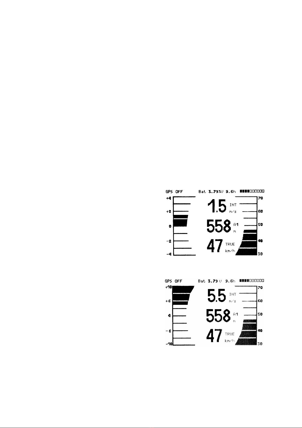
B7 Goto Function
Pressing and holding the Enter/Goto key switches the lower half of the
display into the ‘Goto’ mode. This function allows you to search for a
waypoint (WP) stored in memory and select it as the next waypoint or
goal. The closest five waypoints are shown with the closest waypoint on
top. The number after each waypoint’s name indicates the distance in km
to the waypoint from your current location. Starting with firmware version
2.14 the bearing to this waypoint will also be shown to the right of the
distance. If you press the F1 (Displ.AIti.) key calculated arrival altitudes
to the five waypoints are shown in place of the distance to them.
Basically, five final glide calculations to the waypoints are made at the
same time.
Note: The wind component is taken into consideration for the calculation
only for the waypoint the pilot is directly flying toward (±/20 degrees).
Pressing the Fl (Displ. dist) key again switches back to display the
distances. If you search for a waypoints with the and keys, it will
be selected when the Enter key is pressed. The Goto function can be
deactivated with the F2 (Cancel Goto) key.
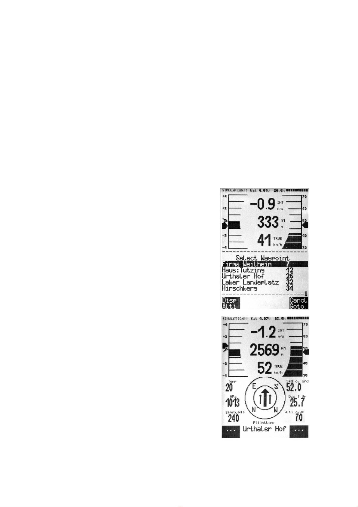
If a strong cross wind is encountered on the way to goal, the correct
flight direction to the destination considering the wind can be found.
The pilot must carefully changes the direction of flight against the wind
until the directional pointer in the compass rose points directly upwards.
The large arrow in the compass will now look like the sample shown.
By doing this you can be sure that the flight path over ground is in a
straight line to goal and thereby the shortest one.
In the user-selectable fields, in the example, the ground speed, the
distance to the waypoint and the calculated arrival height over goal are
displayed. One can interpret this height (Alt a. WP) as the height above
the optimum glide slope to goal. The calculated arrival height
assumes that there is neither lift nor sink along the flight path and that
the wind remains constant. There is certain risk here. Please refer to
E6 Final Glide Calculations.
You can also see, in the user-selected displays, the Altitude above best
glide. This is shown in the figure as Safety Alt, however, in firmware

© Flytec USA, 2003
16
FAI-ROUTE
Quest 3.00 S
Sheets 0.40
Groveland 0.40
Cleremont 0.40
Dean Still 0.40
Highway 33/474 0.40
Waypoint 1 in Route
Quest
Enter Exit
Total Distance: 49
No of Waypoints: 5
Starttime: 12:30
--------------------------------
2.14 this is referred to as Alt a. BG (altitude above best glide). While thermaling before gliding to the waypoint, this
height will display a “0” when the pilot should be able to reach the goal by flying at the best glide speed and the data
field will inverse (white numbers on a black field).
When thermaling you should climb until Alt a. WP shows zero. You can then go on glide at McCready optimum
speed-to-fly. The Alt a. BG (Safety Alt) then shows the pilot how much height he/she will have above the best glide
slope to use, if necessary, to compensate for unexpected sink. Generally the pilot should not proceed to goal if the
Alt a. BG shows zero or negative numbers – reaching goal would be impossible without encountering lift on the way.
B8 Flying Routes
A route is a sequence of waypoints. The waypoints used on a route must first be entered into the 5030’s waypoint
list. To create, change, or delete a route please read section C4 Routes - Create, Alter, Delete. To select an
existing route, press the / Route key for a few seconds. Each route can also be assigned a route name, for
example, “Quest Air Triangle”.
The 5030 stores up to twenty routes. The same waypoint can be used more than once along a route, and the same
waypoint may occur on other routes as well. If a waypoint is used in a route, it cannot be deleted from the waypoint
list, until the route is deleted. There is still the option of looking up other, possibly closer, waypoints without leaving
the current active route, by using the Goto function.
B8.1 Direction arrow to second next waypoint
In the middle of the compass rose, a thick black arrow points to the next
waypoint. Under this pointer is a grey shaded second pointer that points in
the direction of the second waypoint. This second pointer makes it easier
for pilots in competitions to know in advance which direction to turn after
reaching the waypoint cylinder
B9 The FAI Route for Record Flights and Competition Pilots
In contrast to the routes described above, the 5030 uses the terminology
FAI Route to designate routes that have waypoints or cylinders around
waypoints that are mandatory; for example, turn points in competition, or
on FAI record or badge flights. The track log points stored by the 5030 are
used to verify completion of a task in a competition.
When flying an FAI-route the pilot will be notified with an audible alert when
crossing the circumference of a turn point cylinder or when leaving/entering
the start cylinder and the 5030 will automatically switch to the next
waypoint. The FAI route can be called up by pressing and holding the
/Route key and can be selected by pressing the Enter key. Please refer to
section C5 FAI Route - Create, Alter, Delete to set and change routes.
B9.1 Changing a route into the FAI Route:
To change a route to the FAI route go to Route menu under Menu/Routes, select the desired route with the and
keys, and press McC /Mrk key. The display will ask “copy to FAI route?” Press the or key to change the “No”
to “Yes” and press Enter. Any of the waypoints in an FAI Route can be defined to be the start waypoint by pressing
the McC /Mrk key.
In current competitions, instead of being required to fly through FAI photo sectors, the pilot only need enter o exit a
cylinder. The cylinder radius can be set separately for every waypoint, between 20 m and 50 km. The factory setting
is a radius of 400 m. An FAI task is defined by the least distance between the circumferences of each of the
cylinders. However, the Dist. to WP always displays the distance from the pilot’s current position to the center of the
waypoint cylinder.

© Flytec USA, 2003
17
Please note that different radii
for start/landing cylinders have
to be set in waypoint menu.
Therefore, if you have a triangle,
or out and return task, you need
to create two separate
waypoints for the start and
finish, if you start and finish at
the same point. When the 5030
is showing the FAI route the pilot
can set the different cylinder
radii, select the start waypoint,
determine if the race begins by
exiting or entering the start-
cylinder and set the start time.
Because 5030’s GPS receiver
confirms its new position every
second, it only takes one second
for the GPS to know that the
pilot is located within the
cylinder. When this occurs an
unmistakable tone lasting three
seconds sounds and the unit
automatically switches to the
next waypoint in the route. One
or more track log points within
the cylinder are stored at one
second intervals in memory in
the track log, regardless of what
recording interval the pilot has
selected.
In flight mode the pilot can see
on the information display how
many minutes/seconds are left
before the opening of the start
window. In the user-selectable
fields, Dist. to WP informs the
pilot if he/she is inside or outside
the Start cylinder. Only when
the time counter has reached
0:00 and starts to count forward
and the pilot is leaving the start cylinder, will the unmistakable beep signal that the pilot is crossing the start cylinder
circumference. The 5030 will then switch automatically to the next waypoint.

© Flytec USA, 2003
18
Any waypoint in the route can
be defined as a start cylinder.
The automatic switch over to
the next waypoint takes place
when leaving the start cylinder.
When the pilot has left the start
cylinder and the instrument has
switched over to the next
waypoint, pressing the F1 key
allows you to toggle back and
forth between previous and
next waypoint. This is useful
when a pilot wants to go back
and restart the task at a later
time.
Even during the flight, along
the FAI route, it is possible to
select additional waypoints
(perhaps thermal sources) by
pressing and holding the Goto
key. The waypoints are sorted
according to their distance from
the pilot. The waypoints that
are part of the FAI route are
marked with an asterisk in the
displayed list. This means they
must be over flown. The alarm
remains active when entering a
waypoint cylinder along the
route, even if a waypoint not
belonging to the route has
been selected. Press the F2
key to toggle back and forth
between the waypoints of the
FAI route and another
waypoint.
After completing a flight task,
the waypoints in the FAI route
will be included in the data
transferred to a PC as the
designated task section of the
IGC file. SeeYou, CompeGPS,
or other programs that can read and display IGC files, can check if the assigned task was completed correctly.
B10 Relocating Thermals
This function helps the pilot relocate any thermals that are lost. A small arrow pointing up in the double ring of the
compass rose shows the direction to the last thermal with at least a 200 fpm (1 m/s) climb. If this arrow is displayed
at the top in the ring, then you are flying towards the thermal. However, if the arrow is below in the compass rose,
you are going away from the thermal. If you want to take advantage of this function, then the user-selected field
“Dist. to ^”should be displayed. This value indicates the distance from the last thermal to the pilot.
C 5030 Setup Menu (Set-up Mode)
The unit’s menu is opened by pressing and holding the Menu key. To select one of the menu items press theor
key. To navigate to the highlighted sub menu press the Enter key.

© Flytec USA, 2003
19
C1 Basic Settings
A series of settings permit the unit to be programmed according to the user’s wishes. It is always possible to reset
the unit under Menu/Basic Settings/Init EEPROM, which are the manufacturer’s initial basic settings. If you reset
the unit, you are starting over completely. Important! All waypoints and routes will be a deleted if you reset the
unit.
When you have navigated to a desired sub menu, the current setting(s) are displayed. To change a value press
Enter. The value to be changed will blink and can be modified by using the and keys. Pressing the Enter
key installs the new value and a confirmation tone is given and the cursor will advance to the next setting in the
submenu (if there is one). Pressing the ESC key recalls the previous setting.
Term
Meaning
Reference
Factory Setting
QNH
Air pressure at sea level
A2
1013 mB
Record-Interval
Time interval per recorded (track log) point
C2
10 Sec
Sink Alarm
Sink rate required to sound sink alarm
A6
0.8 m/s (160 fpm)
Stall speed
Stall speed and maximum altitude limit
A4, E1
0 mph
Sound
Frequency of Climb and Sink tone, Modulation,
Acoustic Integrator
A6
1200 Hz; 700 Hz Mod = 5;
Acout. int = 8, Pitch = 3:
TEC
Total Energy Compensation
E6
65 %
Polar data
Two polars: Each with two data pairs
1. at min. sink and 2. at higher speed
A8, E4
25 mph at 197fpm
47 mph at 630fpm
Altitude at 1000’
Vario/Speed resp. delay
Time interval for Analogue Vario (range 6-40)
A1
12 ( ≈1.2 sec)
Digital Vario mode
Averager or Net Vario; Averager period (1-30 sec.)
A3
INT; 20 sec.
Time, Date, Year
Difference to UTC; Day, Month, Year
A7.2
Present
Display contrast
Range 0 ... 100 %
70 %
Speedgain vane wheel
Vane wheel 70 ... 150 %
A4
100 %
Speedgain pressure
Pitot sensor 90 ... 150 %
Sensor on/off
A4
100 %
VarioOffset
Threshold for the start of ascent tone - max value is 80
fpm (0.4 m/s)
4 fpm (.02 m/s)
Pilotname
Pilot name entry; max 17 letters
not set
Speed mode
True or Indicated Airspeed,
Speed range upper 19-68mph o lower 12-62mph
E3
0 = true airspeed.
Units
Meter or feet; Km/h or mph or knots. Temperature in
degrees C or F
m; km/h;
Grd C
InitEEPROM
Back to factory settings
C1
No
Erase all records
Deletion of flight memory (all records)
C2
No
Erase all WP& Routes
Deletion of all WP’s and Routes
C3 C4
No
Init GPS
Entry of position for faster satellite reception
B1
Last position
Coordinate Format *
dd°mm.mmm; dd.ddddd; dd°mm’ss”; UTM; Swiss Grid
B6
dd°mm.mmm
Recording Mode
Automatic or manual end of flight recording
C2
Automatic
Average thermal climb
The length of the time interval over which climb rate is
averaged in the previous thermal (0.5 - 10 min.)
A 10
20 = 10min.
Glidertype
Glider class for OLC (HG Rigid Wing or HG Flexible
Wing or Paraglider)
Not set
Glider-Id
Your ham radio call sign for OLC
Not set
McCready
Delay for McCready acc. to climb Acoustic dead band
in % of average thermal climb
A9
7 seconds
30%
Vario display
Circle or Bar
Yes = Circle
User fields
Number of user-fields for pages 1, 2 & 3 (yes=6, no=4)
1 = yes, 2 = yes, 3 = yes
* The highest accuracy is achieved when using the same coordinate format as most GPS models: dd°mm.mmm
(degrees; minutes and decimals of minutes). With all other formats rounding errors can occur. (up to 65 feet or 20
meters)

© Flytec USA, 2003
20
Main Setup Menu
----------------------------------
Basic Settings
Flight Memory
Waypoints
Routes
Simulation
Factory Settings
Optional SW Packages
-----------------------------------
= = = = = = = = = = = = = = = = =
FLIGHT-ANALYSIS
= = = = = = = = = = = = = = = = =
Start: 13.02.02 13:35:43
Stop: 13.02.02 15:13:22
Flight time: 1:37:34
Record-Interval: 10 s
Task: no
Max A1: 2823 m
Max A2: 1154 m
Max A3: 4273 m
Max Vario: 8.9 m/s
Min Vario : 6.6 m/s
Max Airspeed: 73 km/h
Flight Memory
----------------------------
01.03.02 0:43:12
13.02.02 1:37:34
28.01.02 0:24:05
23.01.02 1:02:24
12.01.02 2:11:45
15.12.01 0:34:55
24.11.01 1:07:32
C2 Flight Memory and Flight Analysis
The flight-recording mode does not need to be manually activated since
each flight is automatically saved. The term “barograph” is not used with
respect to the 5030 since a barograph is an air pressure (altitude)
recorder and the 5030 records much more data than air pressure based
altitude.
The flight logging system used in the 5030 registers not only the flight
altitude (from atmospheric pressure) and speed, but also logs (with the
GPS receiver switched on) the time, position of the pilot in the WGS84
coordinate system, the GPS altitude and air speed. The value set in
Menu/Basic Settings/Record-Intervaldetermines the time interval in
seconds. A new data record is written in the 5030’s memory at the
beginning of each time interval. IMPORTANT: Before starting a flight
make certain that the GPS receiver shows at least three receiving
satellites to get a valid recording.
A record interval of one second can be used for performance testing or
aerobatic flights. The factory setting is ten seconds. A flight has to be at
least three minutes long to be logged into memory and have an altitude
difference of at least 100 feet (30 meters). The start of the flight is
recognized as soon as the ground or the airspeed reaches at least 6 mph
(10 km/h). However, up to twenty recording points prior to the “start” of
the flight are included in the flight record. For example, with the record
interval set to 10-seconds, the three minutes before the start of the
logged flight are stored in the flight record. The flight is determined to
have ended if there is no movement for thirty seconds, and no change in
altitude occurs, then the 5030 will display the flight analysis.
The digital signature (a checksum which is used to verify that the flight
record has not been tampered with) is calculated from this moment on
and a notice in the user-selected field draws attention to it. Please wait
until the calculation is completed. You can return to standard display
with a brief press of the Menu key.
If manual recording is selected, recording starts one minute after the
instrument is switched on, and continues until the ESC key is pressed for
three seconds. At this time the display will show “really switch off??”
To confirm the end of the recording press Enter and the generation of the
digital signature begins. This can take one or two minutes. Please wait
until the process is complete.
To view the stored flight records, go to the Flight Memory selection under
the Main Setup Menu (Menu/Flightmemory). Highlight Flight memory
and press the Enter key to display the list of flights. They are stored
according to date with the most recent flight on top. The length of the
flight is also shown in the right hand column, and the date of the flight in
the left hand column. Use the or keys to move through the list and
choose the desired flight with the Enter key. The flight, with its
benchmark figures, is displayed on the Flight Analysis screen. Individual
flights can be deleted from the list by pressing F2 (Del. Flight).
C2.1 Graphic Display of Flights in Map Format
The track log of saved flights can also be viewed on the 5030 display. Go to the Flight Analysis screen (see steps
above) and then press F1 (Show Map). The track log is shown on the display. North is located at the top and
waypoints are plotted with a cross and name. The map scale is displayed in the lower corner of the map.
Other manuals for 5030 GPS
2
Table of contents
Other Flytec GPS manuals


