FMG TLN370 User manual
EQUIPMENT
LLP FARM MACHINERY GROUP OY
LEVYTIE 4 ● 74510 IISALMI
PUH. +358 (0) 20 1984 020 ● FAX 020 1984 029
OPERATORS MANUAL
TLN370/ TLN430
/TLN470/ TLN570
ORIGINAL

OPERATOR MANUAL D00018I (CE 14600)
ROAD DRAGGER
Sivu 2
ORIGINAL
EY-VAATIMUSTENMUKAISUUSVAKUUTUS TUOTTEESTA
LLP Farm Machinery Group Oy vakuuttaa, että markkinoille saatettu kone täyttää direktiivin
2006/42/EY ja standardit SFS-EN ISO 12100 ja SFS-ISO730-1.
FÖRSÄKRAN OM ÖVERENSSTÄMMELSE
LLP Farm Machinery Group Oy försäkrar härmed till marknader att tillförda maskin uppfyller
maskindirektivet 2006/42/EY och standard SFS-EN ISO 12100 och SFS-ISO730-1.
CERTIFICATE OF CONFORMITY FOR A PRODUCT
LLP Farm Machinery Group Oy certifies that the following machine, which has been brought into
the market, conforms to directives 2006/42/EY and standards SFS-EN ISO 12100 and SFS-ISO730-1.
SAMSVARSERKLÆRING FOR MASKIN
LLP Farm Machinery Group Oy bekrefter herved at følgende maskin, som er sendt ut på markedet, er i sam-
svar med direktivene 2006/42/EF, SFS-EN ISO 12100 og SFS-ISO730-1.
Tuote / Produkt / Product / Produkt:
Valmistusnumero / Tillverkningsnummer
/ Serial number / Serienummer:
Teknisen tiedoston kokoaja / Teknisk
dokumentation samlare / Technical file collector: Sakari Ruotanen
Valmistaja / Tillverkare / Manufacturer LLP Farm Machinery Group Oy
/Produsent:
Osoite / Adress / Address / Adresse: Levytie 4, FIN-74510 Iisalmi
Puhelin / Telefon / Telephone: +358 (0) 201 984 020
Paikka / Ort / Place / Sted: Iisalmi
Aika / Datum / Date / Dato:
Allekirjoitus / Underskrift / Signature
/ Signatur:
Nimenselvennys / Namnförtydligande Markku Lappalainen
/ Clarification of signature
/ Tydeliggjøring av signatur:

OPERATOR MANUAL D00018I (CE 14600)
ROAD DRAGGER
Sivu 3
WARRANTY TERMS
•All the products produced by LLP Farm Machinery Group Oy have twentyfour (24) months warranty.
•During the warranty period all the defects in material and in workmanship will be covered, in practical life
FMG will replace defected parts with the new parts. Travelling expenses and freight of parts are not in-
cluded in warranty.
•Warranty will start in the beginning of usage of the product, if nothing else has been agreed.
•Warranty is not covering damages due to misuse of product or use in the purposes where it has not been
designed, lack of services or product has been modified without the permission of FMG.
•Wearing of the normal usage is not covered by the warranty.
•Losses in income, costs and loosen working hours caused by the defected part is not covered by the war-
ranty.
•Warranty repairs should be done by the FMG service dealer or service dealer appointed by the manufac-
turer.
•In case the defects shown in reclamation is not valid or if case otherwise is not in the warranty area FMG
has right to reject from the compensation.
•Warranty reclamation should be done in written form bythe FMG seller within one (1) month after notifying
the defect.
IN CASE OF DEFECT PROCEDURE IS AS FOLLOW:
•clarifythe defect and defected area
•be prepared to deliver defected parts to the manufacturer
•contact FMG seller and make reclamation as follows:
- type of the product and serial number
- delivery date of the product (invoicing date)
- date of the damage
- description of the damage and pictures
- description of the working conditions and the type of the base machine

OPERATOR MANUAL D00018I (CE 14600)
ROAD DRAGGER
Sivu 4
TO THE OPERATOR
•The purpose of this is manual is to provide support and instructions to road dragger
users. Manual contains detailed instructions for driving, operating and maintaining
the road dragger. Make sure that your new road dragger is always handled and
maintained in the correct way in order to ensure reliability and economical operation
for many years.
•We recommend that you read the manual thoroughly. Follow the maintenance and
service program carefully and include the daily maintenance in your normal routine.
This is both you and your tractor interest.
•Maintenance, repairs and adjustments which are not described in this Operator
Manual require the use of special tools and exact technical data. In case of that kind
need please contact your FMG seller or factory.
•Use only genuine FMG spare parts for optimum performance from your tractor and
road dragger. Spares will be sold through the FMG seller.

OPERATOR MANUAL D00018I (CE 14600)
ROAD DRAGGER
Sivu 5
TABLE OF CONTENT
1. SAFETY INSTRUCTIONS......................................................................................................................... 6
2. CONSTRUCTION...................................................................................................................................... 8
3. TECHNICAL SPESIFICATIONS............................................................................................................. 10
4. INSTRUCTIONS...................................................................................................................................... 10
4.1. Usage area ...................................................................................................................................... 10
4.2. Instructions....................................................................................................................................... 10
4.3. Basic adjustments............................................................................................................................ 11
4.4. Adjustment of the rear light.............................................................................................................. 13
5. SERVICE................................................................................................................................................. 14
5.1. Daily service..................................................................................................................................... 14
5.2. Weekly service................................................................................................................................. 14
5.3. Service after 500 hours.................................................................................................................... 14
5.4. Annual service ................................................................................................................................. 14
5.5. Lubrication points............................................................................................................................. 15
5.6. Screws to be tighten........................................................................................................................ 17
6. ELECTRIC CONTROL............................................................................................................................ 18
7. JOYSTICK STEERING ........................................................................................................................... 20
7.1. Road dragger control....................................................................................................................... 20
7.2. Screen.............................................................................................................................................. 25
7.3. USER SELECTION, selection button A........................................................................................... 27
7.4. PARAMETERS, selection button P ................................................................................................. 28
7.5. DIAGNOSTICS, selection button D................................................................................................. 31

OPERATOR MANUAL D00018I (CE 14600)
ROAD DRAGGER
Sivu 6
1. SAFETY INSTRUCTIONS
This section summarizes the regulations that must always be followed when working with the
road dragger. However, these regulations do not exempt the driver from statutory and other
national regulations regarding traffic safety and occupational health and safety. Safety regula-
tions that apply to different types of working sites and existing road traffic laws must always be
observed. Tractor safety regulations accepted by the Finnish occupational safety and health
administration have already been taken into account in the equipment design. The following
section describes general safety precautions that must be observed regarding the use of the
road dragger.
IMPORTANT
Do not use the road dragger for other purposes than it has been de-
signed. Please read this manual carefully before using the implement.
IMPORTANT
Before driving, make sure that all movements and functions work cor-
rectly.
DANGER
When testing different movements of the grader make sure that there is
no one close to tractor. Safety distance 10 meters.
IMPORTANT
Advise other users on the use of the implement and ask them to read the
manual.
DANGER
Do not operate a faulty implement.
IMPORTANT
Use the rotary beacon while working.

OPERATOR MANUAL D00018I (CE 14600)
ROAD DRAGGER
Sivu 7
WARNING
Observe the manufacturer's instructions while working.
WARNING
Pay attention to other road users.
IMPORTANT
Always lower the implement and stop the engine before leaving the cab.
IMPORTANT
Never service or clean an implement that is resting on the hydraulics.
Use mechanical support. Always stop the engine for maintenance.
WARNING
Do not disconnect, connect or tighten pressurized hydraulic plugs.
WARNING
Do not inhale oil mist if a pressurized component becomes damaged. If
oil comes into contact with the eyes, rinse with plenty of water and con-
tact a doctor immediately.

OPERATOR MANUAL D00018I (CE 14600)
ROAD DRAGGER
Sivu 8
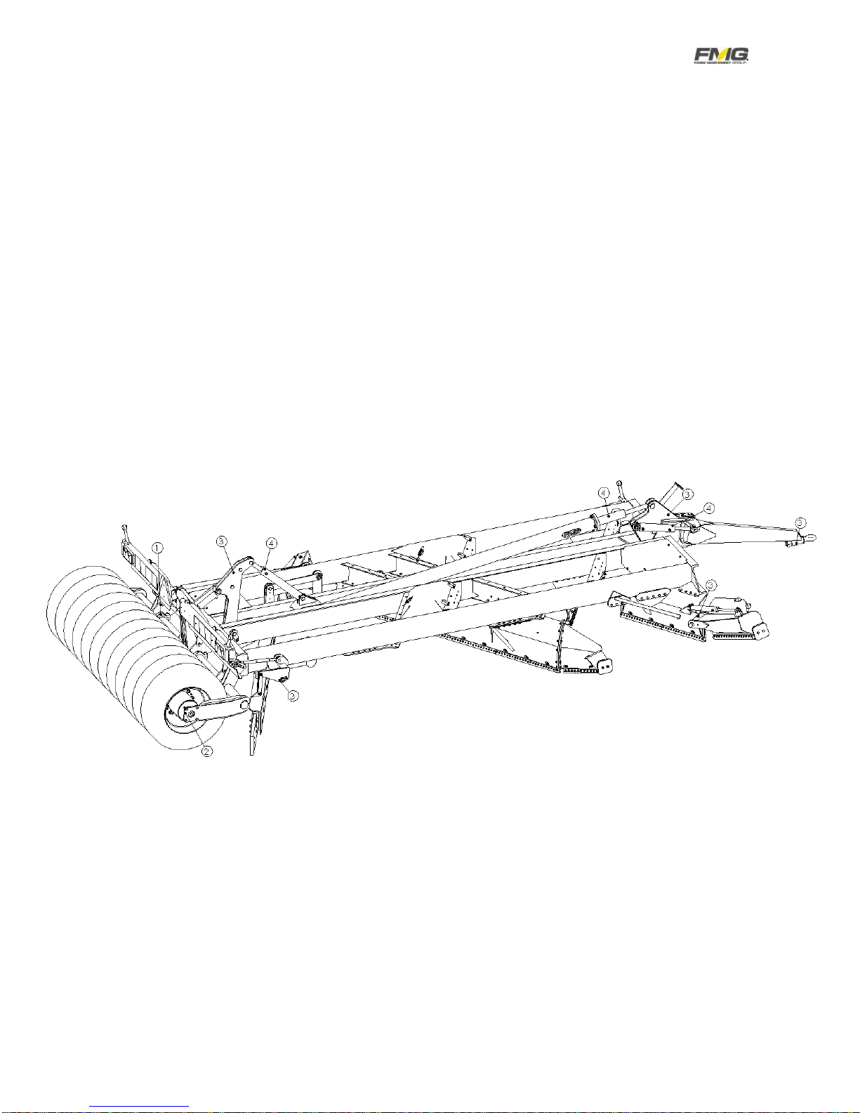
2. CONSTRUCTION
1. Frame
2. Blade frame
3. Extra wing (option)
4. Cylinder
5. Rear axle
6. Swinging bar (option)
7. Stabilizer rod
8. Stone rake
8

OPERATOR MANUAL D00018I (CE 14600)
ROAD DRAGGER
Sivu 9
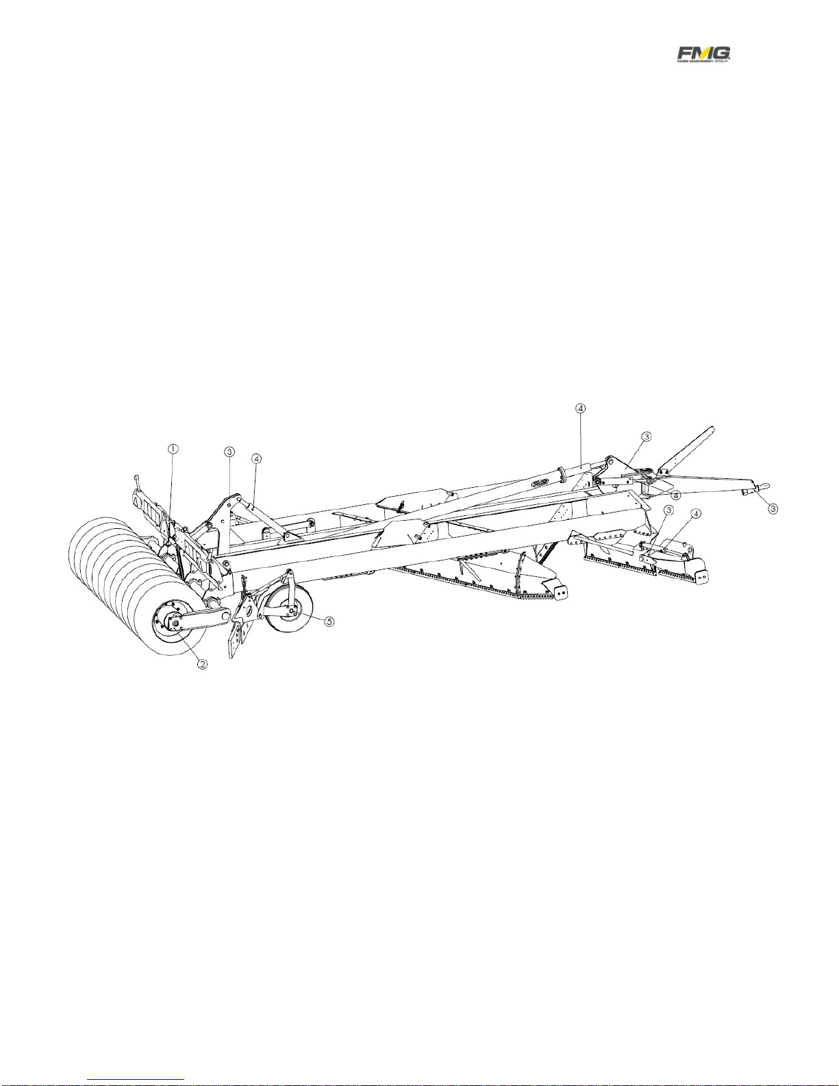
1. Frame
2. Blade frame
3. Extra wing (option)
4. Cylinder
5. Rear axle
6. Swinging bar (option)
7. Stabilizer rod
8. Stone rake with support wheels (option)

OPERATOR MANUAL D00018I (CE 14600)
ROAD DRAGGER
Sivu 10
3. TECHNICAL SPESIFICATIONS
*Without extra wing and swinging drawbar
Sound level is less 70dB (A).
4. INSTRUCTIONS
4.1. Usage area
Road dragger has been designed to balance graveled roads and yards, however
dragger could be used also to the slush removing
4.2. Instructions
Before use take care that dragger is engaged properly to the tractorhitch and all the
hydraulics and electrics are well coupled.
Test drive and make sure that dragger works fully. In case of reparation or isequip-
ment is new take care that hydraulic doesn´t make any impetuous movement be-
cause of air in the system.
When driving take care that you can see whole of the working area and there are
not anyone in that area.
When disengaging dragger take care all the hydraulic hoseshave covers on top of
the quick coupling.
When disengaging dragger from the tractor, at first disengage the pressure hose
and use the joystick in each operating position while tank hose is connected. Then
the pressure from valves will be removed.
In case of leaving dragger to the outdoor storage take care that ground is balanced
to help next engagement.
Model
Width
Width with
extra wing
Length
Number of
blades
Hydraulics needed
Joystick control
Weight
Attachment
to tractor
TLN370
275 cm
310 cm
855 cm
3
Power Beyond
3700 kg
Hitch
TLN430
310 cm
350 cm
890 cm
4
Power Beyond
4350 kg
Hitch
TLN470
310 cm
350 cm
920 cm
4
Power Beyond
4700 kg
Hitch
TLN570
350 cm
370 cm
920 cm
4
Power Beyond
5700 kg
Hitch
OPERATOR MANUAL D00018I (CE 14600)
ROAD DRAGGER
Sivu 11
Maximum allowed driving speed in transportation is 50 km/h.
If road dragger is connected through Power Beyond and it doesn’t move (the pump
pressure doesn’t rise), tighten the stop screw under the plug (Picture 1).
Picture 1. The stop screw under the plug
4.3. Basic adjustments
Picture 2. Road dragger basic adjustment
Road dragger will be driven to the balanced surface and adjusted as follows:
The first blades will be around 50 mm smaller compared to themiddle blade. Work-
ing depth will be adjusted by lifting and sinking front part of the dragger.General
working depth will be adjusted by working depth cylinder (picture 2).
OPERATOR MANUAL D00018I (CE 14600)
ROAD DRAGGER
Sivu 12
Picture 3. Adjustment of the stone rake
Picture 4. Adjustment of the stone rake with support wheels
Stone rake will be adjusted to the same depth or 10 –20 mm higher compared to
the middle blade (Picture 3 and Picture 4).
OPERATOR MANUAL D00018I (CE 14600)
ROAD DRAGGER
Sivu 13
4.4. Adjustment of the rear light

OPERATOR MANUAL D00018I (CE 14600)
ROAD DRAGGER
Sivu 14
5. SERVICE
One of the most important things to keep dragger always in a good shape is service
done in the correct time. Service costs are low compared to the corrections caused
by the undone service. This service contains all the lubrications, checks and adjust-
ments.
5.1. Daily service
- Check the wear of the blade
- Check the fastening screws
- Test all the movements
- Clean the dragger after the working day
- Check the wear of the stinger pins
- Lubricate stinger blade pins
5.2. Weekly service
- Lubricate all the nipples
- Check all the hydraulics and hoses
5.3. Service after 500 hours
- Check the wear of the stinger pins
- Check the tightness of the screws
5.4. Annual service
All above mentioned points. Lubricate all the lubrication points when the season
is over.
NB!
When making service take care that earlier mentioned points will
be done.
NB!
Tightness of the screws should be checked also after the first
drive.
OPERATOR MANUAL D00018I (CE 14600)
ROAD DRAGGER
Sivu 15
5.5. Lubrication points
Lubricate nipples shown in the picture every week. Clean the top of the nipple before
lubrication.
Lubrication points of road dragger that has stone rake without support
wheels:
1.Rear axle 8 units
2.Wheel packer 2 units
3.Joint sleeve 21 units
4.Articulation bearings of cylinders 13 units
OPERATOR MANUAL D00018I (CE 14600)
ROAD DRAGGER
Sivu 16
Lubrication points of road dragger, that has stone rake with support wheels:
1.Rear axle 8 units
2.Wheel packer 2 units
3.Joint sleeve 19 units
4.Articulation bearings of cylinders 13 units
5.Bearings of support wheels 4 units, joint sleeve 2 units

OPERATOR MANUAL D00018I (CE 14600)
ROAD DRAGGER
Sivu 17
5.6. Screws to be tighten
Tighten all the screws after thefirst 10 hours and after that after 500 hours. Check
the tightness of the blade daily basis as follows:
- Screws of the stabilizer rod
- Screws of the wheel packer
- Screws of the blade frame
- Screws of the blade
OPERATOR MANUAL D00018I (CE 14600)
ROAD DRAGGER
Sivu 18
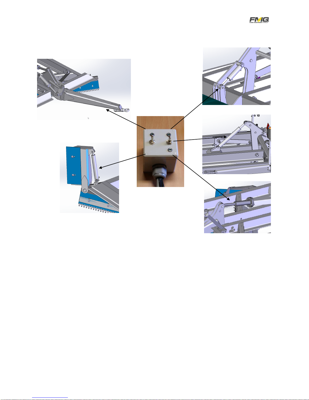
6. ELECTRIC CONTROL
Draw bar
Tilt
Extra wing
Front end lift
Working depth
OPERATOR MANUAL D00018I (CE 14600)
ROAD DRAGGER
Sivu 19

OPERATOR MANUAL D00018I (CE 14600)
ROAD DRAGGER
Sivu 20
7. JOYSTICK STEERING
7.1. Road dragger control
When the grader power is on screen will show FMG logo on a black base (picture 5).
Picture 5. Screen when tractor main power is on
Put the power on by pressing OK-button (Picture 6) and after that screen will be in basicmode
(picture 6).
Picture 6. OK-button
OK-button
Other manuals for TLN370
1
This manual suits for next models
3
Table of contents
Other FMG Construction Equipment manuals


