FOAMICO MO 0145-4 User manual

1 MO 0145-4 NEXT 701613-18_UK 15-04-2019
Operation Manual
FOAMICO NEXT
Mobile station with Compressor
MO 0145-4 (7011613).
Mobil station without Compressor X-AIR
MO 0145-4 (7011618).
2 MO 0145-4 NEXT 701613-18_UK 15-04-2019
Content
1. Introduction 4
1.1 Condition of liability 4
1.2 Guarantee conditions. 4
1.3 Protection against frost 4
1.4 Safekeeping 5
1.5 Declaration of conformity 5
2Safety 5
2.1 Safety during operation of the system 5
2.2 Precautionary measures 5
2.3 Appropriate utilization 6
3Models and symbols 7
3.1 Symbols 7
3.2 Models. 7
3.3 Model Overview 8
4Installation 9
4.1 Safety instructions for Mounting and Installation 9
4.2 Location and Mounting 9
4.3 Water supply 9
4.4 Electrical Supply 9
4.5 Supply of Detergent and sanitizer 10
5Operation 11
5.1 Start and stop procedure. 11
5.2 Rinsing operation 11
5.3 Foam operation 11
5.4 Spray disinfection. 11
5.5 Stop of operation 12
6Troubleshooting / Failures 15
6.1 Troubleshooting 15
6.2 Failures control system 15
6.2.1 The pump does not start 15
6.2.2 The pump will not stop 16
6.2.3 Red light illuminated at the pump 16
6.2.4 Other faults. 17
7Maintenance 18
7.1 Rinsing hose. 18
7.2 Nozzles. 18
7.3 Low pressure valves / guns 18
7.4 Couplings. 18
7.5 Ball valves. 18
7.6 Non-return valves 18
7.7 Suction filter / chemical hose. 18
8Technical data 19
9Spare parts 20
9.1 Enclosure Mobile unit MO 0145- 4. With and without compressor 20
9.2 Overview Mobile unit MO 0145-4 with compressor 21
9.3 Overview Mobile unit MO 0-5 without compressor 23
9.4 Pipe system Rinse and foam block 25
9.5 Spare parts Rinse and foam block. 1001040-44 - 1001218 26
9.6 Spare parts Rinse and foam block. 1001309-13 28
9.7 Spare parts foam and rinse block, positioning ring, injector 30

3 MO 0145-4 NEXT 701613-18_UK 15-04-2019
9.8 Spare parts foam / rinse block, positioning ring, injector. Without compressor 30
9.9 Spare parts: Air regulator complete with bracket 1001488 31
10 Electrical diagram 32
10.1 Spare parts Control box compressor 1001492 33
10.2 Flow diagram MS0145-0 –MS0145-5. With compressor 34
10.3 Flow diagram MO 0145-1 –5 without compressor 34
11 Name plate 36
12 Declaration of Conformity 37

4 MO 0145-4 NEXT 701613-18_UK 15-04-2019
1. Introduction
FOAMICO congratulates you with your new FOAMICO Cleaning system. The NEXT MO 0145- serie are
developed to be used for professional cleaning purpose.
The system is manufactured mainly of high grad stainless steel. It is designed to meet today’s high hygiene
standards
Attention! To use and operate the system this manual must be read carefully.
1.1 Condition of liability
The responsibility for the treatment and operation in an appropriate manner rests with each individual user.
This it is of great importance that this manual is available to the sanitary employee at any time
1.2 Guarantee conditions.
For a period of 12 months from the date of delivery your dealer warrants for parts which don’t function due
to defects of material or production. This guarantee does not cover wearing parts (as described in the section
about spare parts). This guarantee is covering the replacement or repair of the defect part. Any dismounting,
forwarding, and mounting expenses are paid by the purchaser. The costs for any possible return from
FOAMICO after finished repairs rest with FOAMICO. The defect parts are the property of FOAMICO
Claims which might be raised for any other legal reason, or normal wear and tear, as well as damage on parts
which can be related to negligent or wrong treatment, are not covered by this guarantee.
This guarantee does not cover at all, if the system has been exposed to frost.
This guarantee becomes void if changes or repairs have been implemented by non-authorized persons. Any
claims under the guarantee will only be accepted if they are announced to
FOAMICO immediately after the damage has been observed. This guarantee becomes void as soon as the
system changes ownership.
Dealers and FOAMICO cannot be held responsible for personal injuries, damages to equipment, loss of
earning including those caused by production loss, loss of stock or the like, which might arise from
inappropriate or delayed delivery of the sold product, regardless the reason, including defects in production
or material. In addition, please read our usual terms of sale and delivery
WARNING
Due to the nature of low pressure cleaning systems Pressure surges can occur. The installer is responsible for
dimensioning the supply line to be able to adapt Pressure surge.
Dealers and FOAMICO cannot be held responsible for personal injuries, damages to equipment surrounding
rooms, Water Supply line or water outlet line.
1.3 Protection against frost
The equipment should only be installed in frost free rooms.
Prior to being exposed to frost, the system must be emptied for water (frost protected). Even shorter periods
of exposure to frost can damage the equipment.
5 MO 0145-4 NEXT 701613-18_UK 15-04-2019
This symbol refers to safety and danger moments. Neglect of these instructions can cause damage on persons
and objects.
1.4 Safekeeping
You are requested to store this manual in a place where it is at your disposal at any time, and it should be
handed over to the person responsible for this product. Should the manual get lost, please don’t hesitate to
require another one from your agent.
1.5 Declaration of conformity
We FOAMICO declare that this product is in conformity with the following directives:
- Machinery (2006/42/EC)
2 Safety
2.1 Safety during operation of the system
Suitable working clothes are recommended, e.g. as protection against 70°C hot water. Goggles, respirators,
and rubber gloves should always be used. The use of non-slip footwear is recommended, because due to
water and foam the floor sometimes can get slippery.
Do not connect or use detergent before having read the instructions from the Detergent supplier. Always
consult the Detergent supplier to get instructions for correct use. Wrong use of detergent can be dangerous, it
can produce poisonous gas, great chemical burns an allergic reaction.
The system should not be started up before the operator using the system, has been instructed in the correct
utilization, adjustment, and maintenance of it. Never direct the water jet towards persons. Make sure that the
couplings” lock” when the hose and nozzles are connected. Always follow this procedure before use. Always
depressurize the system after use. This is done by first closing the valve for the water supply and afterwards
opening the low-pressure valve or gun.
During operation of the system: ensure that the low-pressure gun/valve is closed, before releasing the
coupling and change the nozzle. When the low-pressure gun/nozzle is opened, the water jet will cause a
certain back pressure. Make sure to have a strong grip on the handle and a firm foothold.
The noise level from the equipment is less than 70dB (A). During rinsing, the operator is exposed to a higher
noise level. This is caused by the impact from the water jet on the surroundings. It is therefore recommended
the use ear protectors during the cleaning process
Never direct the water jet towards electrical equipment. Avoid water in electrical plugs.
Switch of the power supply, before plug in or remove a plug from an electrical socket.
Attention! Use only original FOAMICO Nozzles, hoses, couplings and spare parts.
2.2 Precautionary measures
The construction of the system is in accordance with the generally adopted, technical requirements and the
stipulations concerning working environment and accident prevention. Therefore, the equipment must be in
its best technical state before being used, and must only be utilized according to its requirements and by

6 MO 0145-4 NEXT 701613-18_UK 15-04-2019
observance of the precautionary measures and operational instructions. Disturbances, which might influence
the safety in particular, must be rectified immediately.
2.3 Appropriate utilization
FOAMICO low-pressure system is manufactured with the purpose of:
Rinsing with water, spreading foam and disinfection within the stated boundaries.
Any other kind of application or use beyond this is considered to be inappropriate and deviant concerning
the requirements, and may lead to dangerous situations. FOAMICO is not liable for any sequential damages
brought about by this.
Appropriate utilization includes the following:
The instructions, regulations, and recommendations given in this manual.
The observance of the prescribed intervals for inspection and maintenance.
The correct maintenance for good operational condition of the system.
The observance of the prescribed conditions for the environment and operation.
7 MO 0145-4 NEXT 701613-18_UK 15-04-2019
3 Models and symbols
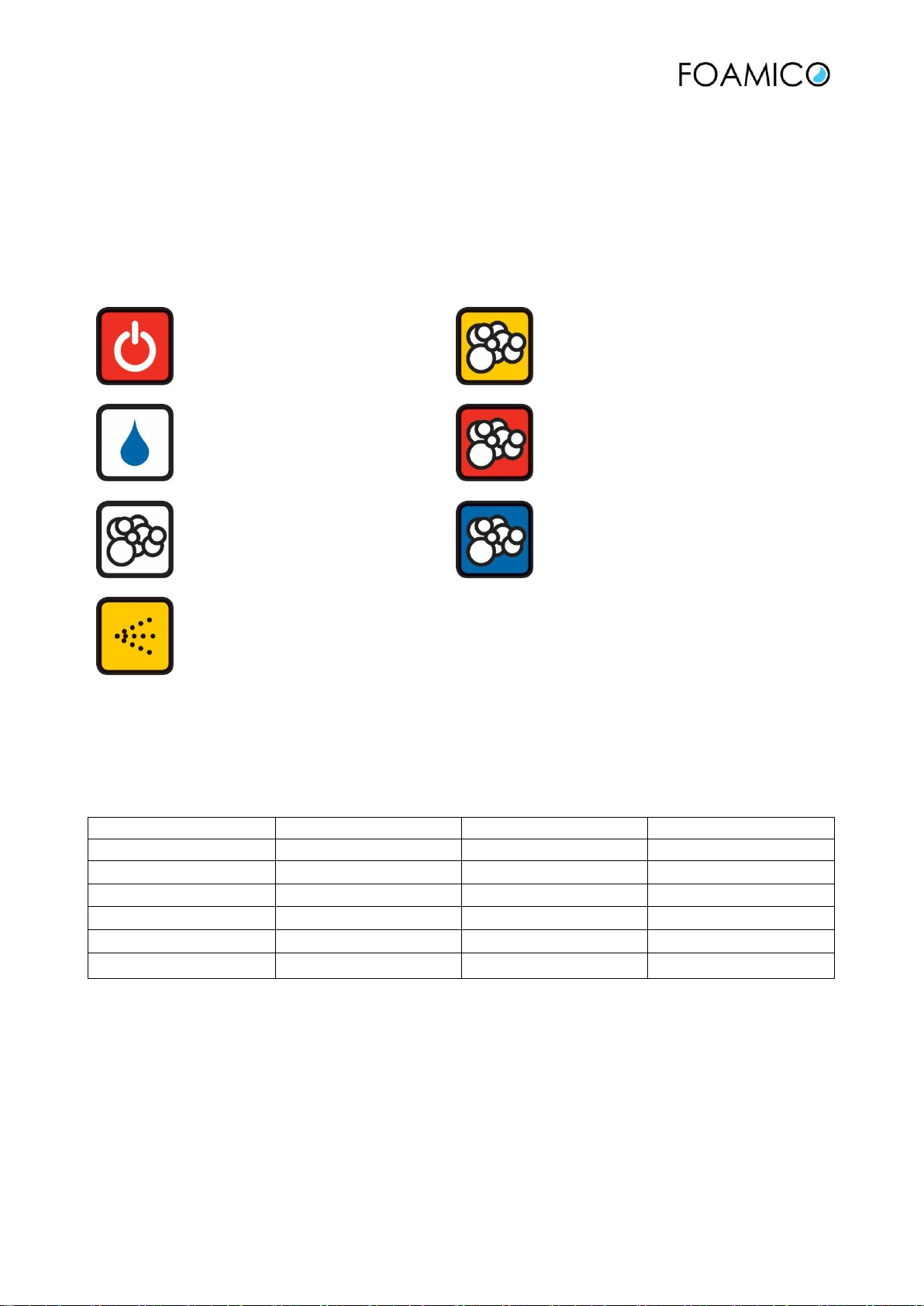
3.1 Symbols
FOAMICO Mobile unit come with a complete set of symbols. The symbols will make operation easier.
Attention! The symbols should be installed with a supervisor from the chemical supplier.
Off
Foam disinfection
Rinsing
Foam Cleaning
(e.g. acid)
Foaming
Foam Cleaning
(e.g. Alkaline)
Spray disinfection
3.2 Models.
FOAMICO supplies this NEXT Mobil Unit in 6 different versions. The actually version can be seen at the
nameplate (See 11)
Model Nummer
1. Injector
2. Injector
3. Injector
MO 0145-0
Foam
MO 0145-1
Foam
Spray disinfection
MO 0145-2
Foam
Foam
MO 0145-3
Foam
Spray disinfection
Spray disinfection
MO 0145-4
Foam
Foam
Spray disinfection
MO 0145-5
Foam
Foam
Foam

8 MO 0145-4 NEXT 701613-18_UK 15-04-2019
3.3 Model Overview
Typ 1
MO 0145-1
Typ 2
MO 0145-2
Typ 3
MO 0145-3
Typ 4
MO 0145-4
Typ 5
MO 0145-5
Typ 0
MO 0145-0
9 MO 0145-4 NEXT 701613-18_UK 15-04-2019
4 Installation
4.1 Safety instructions for Mounting and Installation
IMPORTANT!
Never install or apply damaged products. Claims concerning damages must be made to the carrier
immediately.
IMPORTANT!
Work in the connection with installations, start up, and maintenance on the FOAMICO cleaning systems
should only be done by authorized electricians, because the valid national regulations concerning prevention
of working accidents. (e.c. high voltage regulations: EN 60204, VBG4 DIN-VDE 0100/0113/0160) must be
respected. In cases of irregular installations there is a risk for major damages on both material and people.
4.2 Location and Mounting
The system should always be located in a frost-free room. Stationary system must always be mounted where
the surfaces are of solid quality, and when applicable the fastening must always be done with the delivered
bolts and raw plugs. Holes for wall brackets must be drilled according the dimensional drawing.
The Main Station should be connected to an adequate pipe system. This should correspond to distance from
the water supply, the maximum water flow and vertical distance from the boosting System.
4.3 Water supply
ATTENTION! Connection to water supply should always be done in according to local and national
standards.
If the legislation in your country requests safeguards for reverse current, this must be provided for.
WARNING
Due to the nature of low pressure cleaning systems Pressure surges can occur. The installer is responsible for
dimensioning the supply line to be able to adapt Pressure surge.
BEFORE mounting the system, the piping must be flushed with water in order to remove possible parts or
dirt.
ATTENTION. At the supply pipe to the main station a valve and filter must be installed. We recommend
using Original FOAMICO installations set. The water should be connected to the inlet shown in POS A. fig.
5.1
ATTENTION! The pump must be filled with water and vented. If the pump runs dry it may be damaged.
Open the vent valve POS. L fig. 5.1, until all air is out of the pump.
AFTER mounting the system flushing of the pipes must always be done with the system in “rinsing mode”,
to avoid any impurities in the injector system. Please keep rinsing until the rinsing nozzle shows an
invariable clean water jet coming out.
4.4 Electrical Supply
10 MO 0145-4 NEXT 701613-18_UK 15-04-2019
WARNING
The user or the installer is responsible for the installation of correct Grounding and protection according to
current national and local standards. All operations must be carried out by qualified personnel.
WARNING
Never make any connections in the pump terminal box unless electric supply circuits have been switched off
for at least 5 minutes.
ATTENTION! Connection the power supply must only been made by authorised electrician’s´.
ATTENTION! The connection has to be done to a main switch installed next to the station.
ATTENTION! Always consult the pump manual before making the connections
Supply voltage and mains: 3 x 380-400 V. -10%/ + 10 %, 50/60 Hz, PE.
ATTENTION! The voltage and frequency is marked on the main station’s and the pumps nameplates. Make
sure they are suitable for the electricity supply of the installation site.
4.5 Supply of Detergent and sanitizer
ATTENTION! The handling and connection should be done according to description from the Detergent
supplier.
ATTENTION! Always follow the safety instructions for the detergents. They should always be available
together with the detergents.
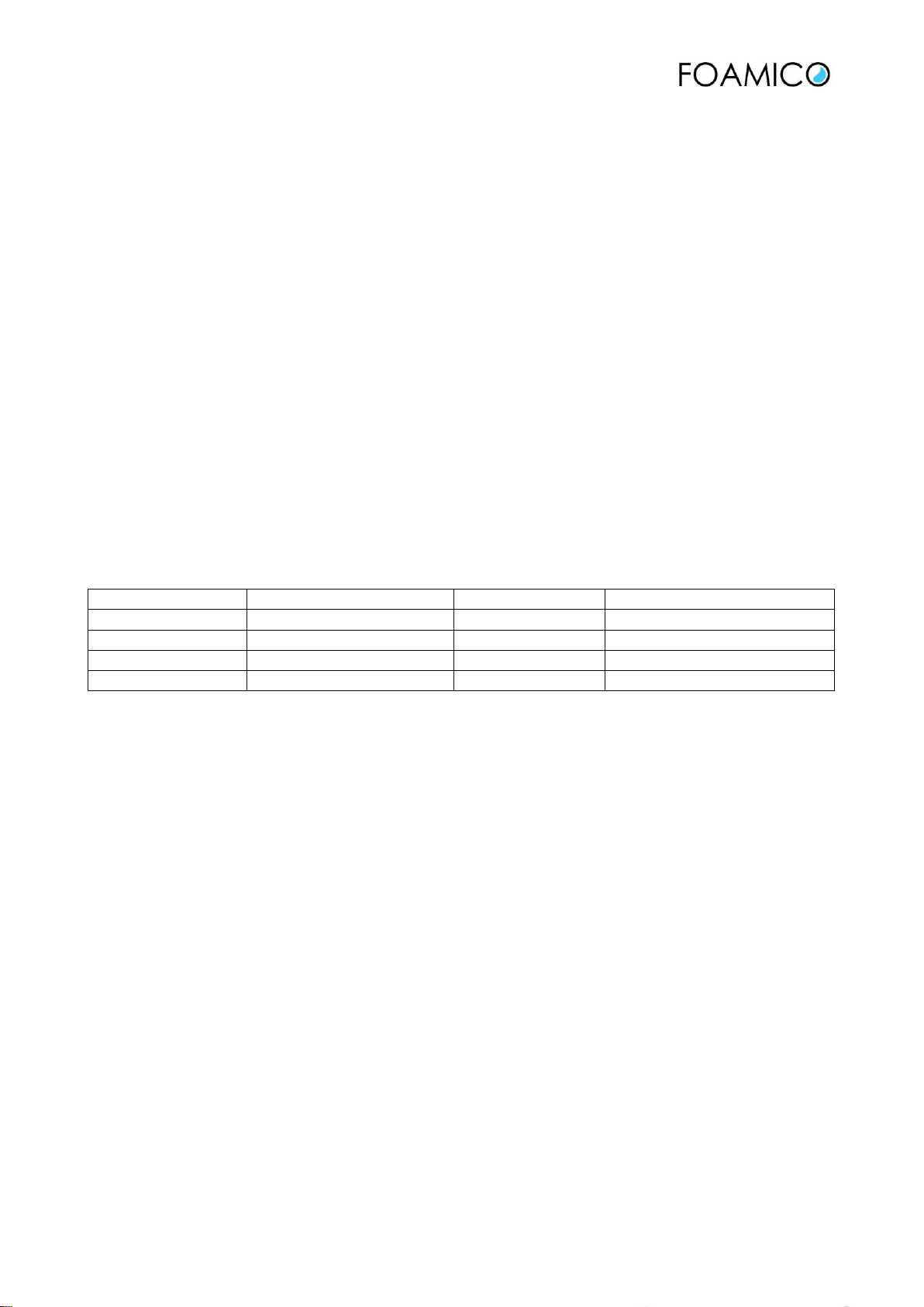
Before connection of the detergent, the concentration Nozzle must be installed.
Size mm
Concentration % **
Size mm
Concentration % **
0,5
1,4
0,9
3,0
0,6
1,7
1,1
3,8
0,7
2,0
1,3
4,8
0,8
2,5
1,5
6,0
** Concentration varies from detergent to detergent depending on viscosity. Above figures is based on a
detergent with a viscosity as water.
Install the nozzle POS G. Fig. 5.1 and install the suction hose POS G fig 5.1
Places the suction hose in the detergent container.

11 MO 0145-4 NEXT 701613-18_UK 15-04-2019
5 Operation
5.1 Start and stop procedure.
ATTENTION! Do not start the mobile station until the pipe system has been filled with water and vented.
Do not start the Mobile station until the pump has been filled with water and vented. If the system runs dry
or partly filled the pump and other components may be damaged.
Start:
1. Connect the hose to the coupling POS E fig. 5.1 make sure the valve is closed.
2. Make sure the low-pressure valve/ gun at the end of the hose is closed
3. Open the ball valve POS E fig.5.
The mobile station is now ready.
4. The mobile station is designed and programmed so it can operate with high and low pressure. By turning
the switch POS. K, Fig. 5.1, the operation mode can be changed between high and low pressure. If the
switch is in position I, the machine will deliver 25bar low-pressure. When the switch is in position II, 40 bar
high-pressure will be delivered.
STOP:
1. The mobile station is stopped by turning the Handle POS D fig 5.1 into
2. ATTENTION! When the system is not used it is recommended to turn the handle into stop position
3. ATTENTION! In case of service the Electrical main switch shall always be turn off.
5.2 Rinsing operation
1. Mount the rinsing nozzle or rinsing pipe in the coupling at the low-pressure valve / gun (marked with blue
or green protection)
2. set the handle POS D fig. 5.1 in rinse position
3. The system is now ready for rinsing. Rinse by open the low-pressure valve / gun.
4. ATTENTION! After rinsing the hose must be depressurized. Close the valve POS E fig. 5.1 and open the
low-pressure valve/gun. The hose can now be disconnected.
5.3 Foam operation
1. Mount the foam nozzle in the coupling at the low-pressure valve / gun (marked with white)
2. set the handle POS D fig. 5.1 in rinse position.
3. Adjust the air pressure to 4-6 bar on the regulator POS H fig. 5.1 (differs from detergent to detergent.
Often has to be fine-tuned during first time foaming)
4. The system is now ready to foam. Apply foam by opening the low-pressure valve/gun
5. After foaming the system must be rinsed with clean water. Place hose for detergent in a container with
clean water. Open the low-pressure valve/ gun for minimum 15 sec.
6. ATTENTION! Set the handle POS D fig. 5.1, back in rinse position when Foam operation is ended.
7: ATTENTION! Before choosing another cleaning operation with another chemical, the system must be
flushed with clean water for at least 30 seconds. This is done by following the instructions in 5.2 rinsing
operation”
5.4 Spray disinfection.
1. Mount the disinfection nozzle in the coupling at the low-pressure valve / gun (marked with yellow
protection)
12 MO 0145-4 NEXT 701613-18_UK 15-04-2019
2. set the handle POS D fig. 5.1 in disinfection position
3. The system is now ready for sanitizing. Sanitize by open the low-pressure valve / gun.
4. After sanitizing the system must be rinsed with clean water. Place the hose for disinfection in a container
with clean water. Open the low-pressure valve/ gun for minimum 15 secs
5. ATTENTION! Set the handle POS D fig. 5.1, back in rinse position when Foam operation is ended.
6: ATTENTION! Before choosing another cleaning operation with another chemical, the system must be
flushed with clean water for at least 30 seconds. This is done by following the instructions in 5.2 “rinsing
operation”
5.5 Stop of operation
1. Make sure that the injectors have been rinsed with clean water
2. ATTENTION! When not used the main station must be shut off. Turn the Handle POS D fig. 5.1 into stop
position . Close the valves at POS E fig. 5.1
3. Depressurize the hose by opening the low-pressure valve /gun.
4. Disconnect the hose.
13 MO 0145-4 NEXT 701613-18_UK 15-04-2019
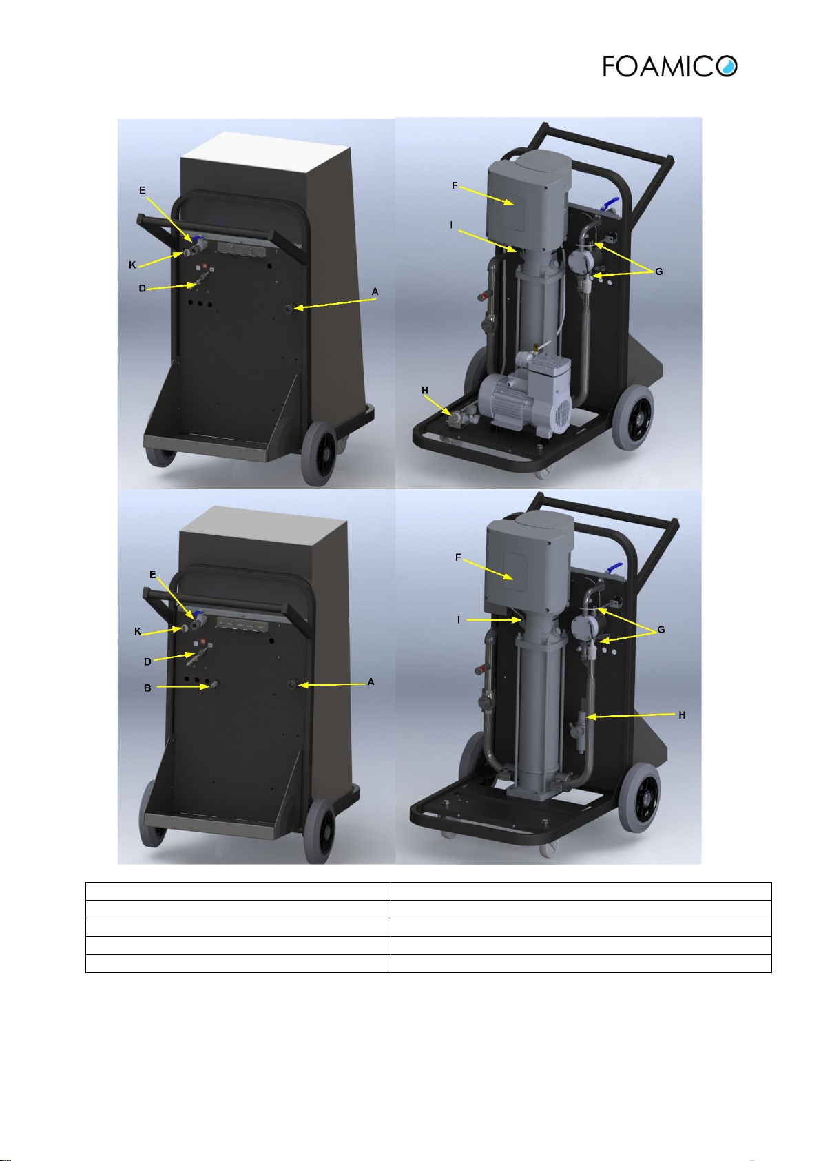
FIGURE. 5.1
A. Connection for water supply
B. Compressed air connection
D. Handle for selecting operation
E. Connection for hose. Rinse and foam
F. Advanced control panel
G. connection for limiting nozzles. Adjust concentrations
H. Pressure reducer for air
I. Bleeding valve pump
K. Low–or high- pressure -selection
Table 5.1
14 MO 0145-4 NEXT 701613-18_UK 15-04-2019
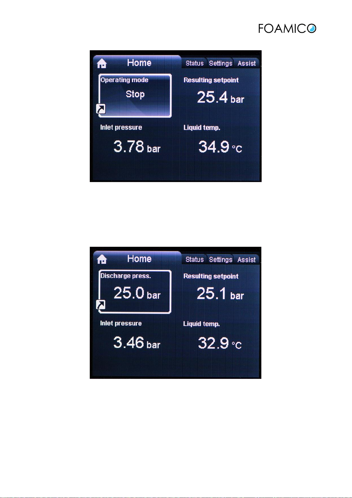
FIGURE. 5.2 Display photo Pump stopped
•Operating mode: Stop. Pump is stopped
•Resulting setpoint. Setpoint = inlet pressure + maximum pump pressure. (maximum setpoint 40 bar)
•Inlet pressure: Actual measured inlet pressure.
•Liquid temp. : water temperature in top of the pump.
FIGURE. 5.3 Display photo Pump running
•Discharge press: Actual discharge pressure from pump. (maximum setpoint 40 bar)
•Resulting setpoint. Setpoint = inlet pressure + maximum pump pressure. (maximum setpoint 40 bar)
•Inlet pressure: Actual measured inlet pressure.
•Liquid temp.: water temperature in top of the pump.

15 MO 0145-4 NEXT 701613-18_UK 15-04-2019
6 Troubleshooting / Failures
ATTENTION! When the system is serviced, the main power switch must always be switched off.
6.1 Troubleshooting
Fault
Cause
Action
No rinsing pressure.
Mobile station not started.
Start the mobile unit.
Too many users on the same time.
Check maximum number of users.
The ball valve at the inlet of the system is not
opened.
Open the ball valve.
Unstable rinsing pressure.
Unoriginal rinsing nozzle with too high water
consumption is used.
Change to master rinsing nozzle –observe
technical data for model.
The system does not suck up any
detergent into the injector.
Operation handle is not in position” foam”.
Turn into position” foam”.
Limiting nozzles is to small
The dosing must be adjusted. Check with
the description from the detergent supplier.
Change he nozzle.
Limiting nozzle is blocked by chemical remains.
Change the limiting nozzle.
Injector system is blocked by chemical remains.
Injector system and water nozzle in the
injector must be disassembled and cleaned.
Leakages on the detergent inlet. Air is drawn into
the detergent line
Check the chemical inlet. Change the
suction hose.
Blocked suction filter at the end of the suction
hose.
Clean or change suction filter.
Empty chemical container.
Change to new chemical container.
Suction filter above fluid level in the chemical
container.
Lead the suction filter underneath the fluid
level.
No compressed air to the system.
Open the air inlet to the system.
The rinsing hose is” pounding”.
Chemical product mixed with water.
Exchange the chemical container.
The used chemistry is not a foam product.
Change to a foam product.
Injector system is blocked by chemical remains.
Injector system and water nozzle in the
injector must be disassembled and cleaned.
Limiting nozzle is blocked by chemical remains.
Change the limiting nozzle
Fault
Cause
Action
Low foam quality.
No compressed air to the system.
Open the air inlet to the system.
Wrong product.
Change to a foam product.
Unoriginal foam nozzle is installed.
Change to original 50/200 foam nozzle,
installed with white nozzle guard.
Insufficient air supply to the system.
Min. 150 l/min. and max. 200 l/min. at 4-6
bars is requested.
Air pressure not set correct.
Is adjusted on the air regulation valve to
be 4-6 bars.
Operation selector is not in the position” foam”.
Turn it into the position” foam”.
6.2 Failures control system
6.2.1 The pump does not start
The pump does not start even though there is flow through the pump. Do the following:
Reset the unit. Turn the Handle POS. D fig 5.1 into position for 5 seconds. Turn the Handle POS. D fig
5.1 into rinse position . If this does not help and the green light at the pump is not illuminated check the
16 MO 0145-4 NEXT 701613-18_UK 15-04-2019
power supply. If the green light at the pump is illuminated and the pump is not running investigate the flow
switch. Is the pump still not running call a service technician.
6.2.2 The pump will not stop
The pump does not stop. Investigate the following:
Check for water leakages in the pipe system
Check the non-return valve
Check the flow switch
Reset the unit. Turn the Handle POS. D fig 5.1 into position for 5 seconds. Turn the Handle POS. D fig
5.1 into rinse position . If the problem is still not solved, contact service technician.
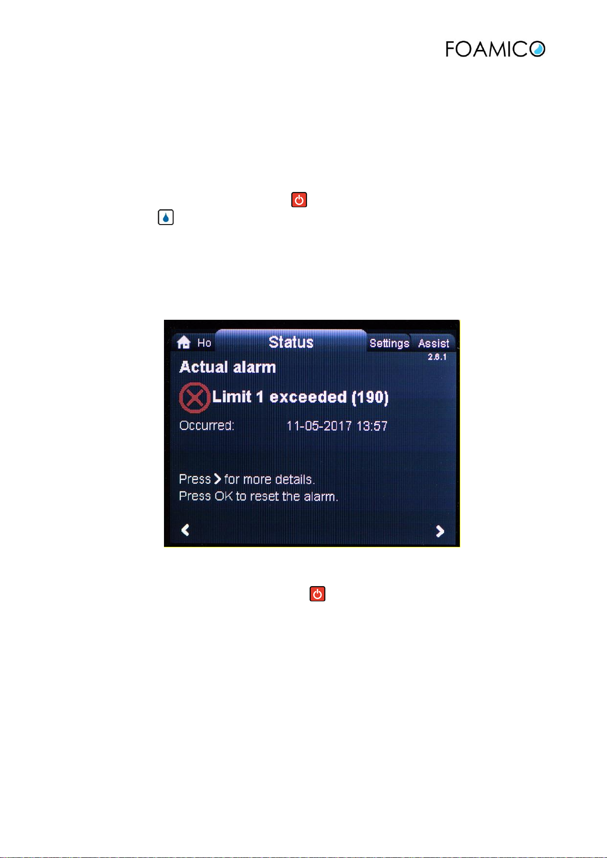
6.2.3 Red light illuminated at the pump
The pump does not start or has suddenly stopped and the red light is illuminated, then investigates the
following:
-Dry run –Limit 1 exceeded: Is the supply pressure higher than 2 bar?
Limit 1 exceed: The inlet pressure has been lower than 0,6 bar for more than 3 seconds.
Check the water supply. Minimum supply is 2,0 bar at full flow.
Reset the unit. Turn the Handle POS. D fig 5.1 into position for 5 seconds. The unit will start when
there is water consumption
Follow the instruction at the display to set it back to the home screen, fig. 5.2
17 MO 0145-4 NEXT 701613-18_UK 15-04-2019
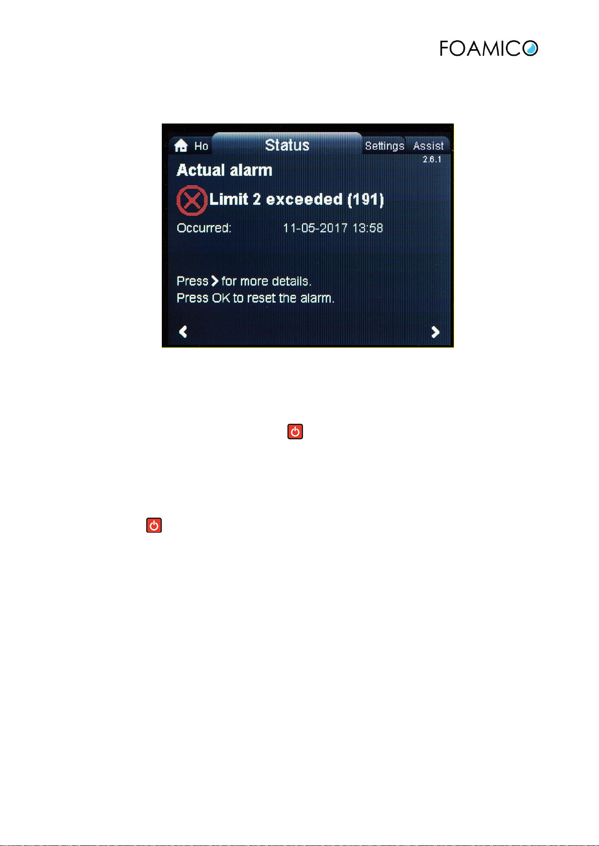
-High water temperature Limit 2 exceeded: is the supply water below 70°C/158°F?
Limit 2 exceed: The water temperature at the top of the pump has been higher than 80°C/176°F for more
than 3 seconds.
Check the temperature setting for the water supply. Maximum water temperature is 70°C/158°F.
-ATTENTION: Before it is possible to reset the system, it must cool down to below 80°C/176°F. This may
take 15-25 minutes
Reset the unit. Turn the Handle POS. D fig 5.1 into position for 5 seconds. The unit will start when there
is water consumption
Follow the instruction at the display to set it back to the home screen, fig. 5.2
High motor temperature –pump has been overloaded –reduce load. *
If the failure has been one of the above and the problem has been solved. Reset the unit. Turn the Handle
POS. D fig 5.1 into position for 5 seconds. The unit will start when there is water consumption.
6.2.4 Other faults.
Read the display and consult the Grundfos manual which were delivered together with the equipment.
If this do not solve the problem Contact a service technician.

18 MO 0145-4 NEXT 701613-18_UK 15-04-2019
7 Maintenance
ATTENTION! When the system is serviced, the main power switch must always be switched off.
7.1 Rinsing hose.
ATTENTION! The rinsing hose should be checked for any damage or week point before taking it into use
every day. A damaged hose can potential be dangerous.
Do not drive across the hose. Be careful not to damage the hose on any sharp edged or corners.
After use clean the outside of the hose. Store it on a hose hanger.
For security reasons, it is recommended to change the hose at least once every 12 month.
7.2 Nozzles.
Nozzles are warned over time. And warned out nozzle is less effective. It can result in less rinsing power,
higher water usage, higher chemical consumption. Check the nozzles on a regular basis. 1 to 2 times every
month is recommended. Change the nozzle if they are damaged. To be sure you will get the optimized result
we recommend using FOAMICO nozzles.
7.3 Low pressure valves / guns
They must be checked regular. The nut on the handle has to tighten regularly. Check couplings, swivels,
handles for any damaged. A damaged part must be changed for security reasons.
7.4 Couplings.
Couplings should be cleaned and greased on a regularly basis. Use only approved grease. This will extend
the life time of couplings. Always make sure there is a nozzle or lance mounted in the coupling before
opening. Rinsing through an open coupling can damage the O-rings.
7.5 Ball valves.
Every ball valve on the inlet for water inlet for air outlet for water/foam and outlet for sanitizer must be
adjusted
First time, after one week, and then once every month. Tight the nut on the handle to avoid leakage
7.6 Non-return valves
ATTENTION! Non-return valves are very important to secure a correct function of the system.
Non-return valves for air: The system has 2 non- return valves for air. The purpose of these is to prevent
water running back into the air system. Due to the potential risk, the air system for the cleaning system must
be separate from other air systems.
ATTENTION! Never leave the valve for air open. Always secure it is closed when not foaming!
If leakage of water is observed anywhere in the airline, both non-return valves must be changed.
- Non-return valve for chemical: The system has one for each chemical intake. The purpose is to prevent
water running back into to chemicals. It will dilute the chemical and result in none or bad foam quality and to
low concentration
ATTENTION! Non- return valves should be checked once every week. It is recommended to change every
1-2 year. Use only Original FOAMICO non-return valves.
7.7 Suction filter / chemical hose.
The suction filter for chemical should be clean once every week. It is recommended to change filter and
chemical inlet hose every year.

19 MO 0145-4 NEXT 701613-18_UK 15-04-2019
8 Technical data
Unit MO 0145 -4
Water connection:
Min./max. inlet pressure bar 2/10
Max. water consumption l/min. 60
Max. Temperature °C 70
Pipe dimension inlet inch ¾”
Pipe dimension outlet inch ½”
Power Supply:
Standard voltage V 380-400
Hz 50/60
Max power consumption kW 6,0 pump + 1,0 Compressor
Nominal current with compressor (Foam) A 14,8-11,6 A
Nominal current without compressor A 14,3-11,1 A
Fuse A 16
Dimension mm22,5
Dimensions (WxHxD) mm 725 x 1225 x 985
Weight with compressor kg 150
Weight without compressor kg 135
Accessories:
Standard rinsing nozzle: Stainless steel Nozzle type 25/30
Standard rinsing lance: Stainless steel Nozzle type 25/30.
Standard foam nozzle type 1. Stainless steel Nozzle type 50/200
Alternative foam nozzle type 2. Stainless steel Nozzle type 65/150
Standard Sanitizer nozzle Stainless steel Nozzle type 40/30

20 MO 0145-4 NEXT 701613-18_UK 15-04-2019
9 Spare parts
9.1 Enclosure Mobile unit MO 0145- 4. With and without compressor
Figure 9.1 Mobile station enclosures
This manual suits for next models
2
Table of contents
Other FOAMICO Cleaning Equipment manuals


Popular Cleaning Equipment manuals by other brands


Clarus Technologies
Clarus Technologies PCS-25 Operator's manual

Dremel
Dremel 760 owner's manual

Kärcher
Kärcher K 2.93 manual

Sumake
Sumake Air Twister SA-4012MAl Air Twister SA-4012M instruction manual

Kärcher
Kärcher PW 10 operating instructions

Ultrasonic
Ultrasonic Ultra 3800FLT Operational Instruction Manual

Lechler
Lechler IntenseClean Hygienic 5TA Series Maintenance instructions

Drester
Drester Boxer Double Combo DB22C Operation manual

LAMETAL
LAMETAL Stark THM 2500 Original operating and maintenance instructions

Sealey
Sealey APMS67 manual

Garten Meister
Garten Meister 94 60 24 Original instructions

e.ziclean
e.ziclean Cycloboost R manual