LAMETAL Stark THM 2500 Manual

Original
Operating and maintenance
manual
Back broom (2500, 3000)

Sivu 2 / 20
General
Congratulations on the purchase of your STARK Back broom!
For us, the long lifecycle and efficiency of your new equipment is a priority. To keep the broom in top working condition,
read this manual carefully before using the equipment.
STARK products are engineered and manufactured in Finland, and each of them is equipped according to the needs of
the customer.
Never let anyone operate or maintain the device without reading this manual carefully! Always make sure that safety
precautions are observed in use and maintenance. Keep this manual for future reference and make sure to hand it over
to a new owner.
The cornerstones of the product development of STARK attachments are quality, durability and economy. The products
are engineered to be high-performing, safe and durable in professional use. Any feedback on our products is welcome
and contributes to the further development of our products. If you have any questions about the use or maintenance of
the broom, please contact us by e-mail: info@stark.fi
Visit our webpage www.stark.fi for the complete product range, including new products.
The manufacturer reserves the right for structural and technical changes without prior notice. Therefore, some pieces of
information given in the manual may have changed after printing this manual.
Read before use
Make sure you know your equipment before you start using it.
Equipment may be operated only by an individual who is thoroughly familiar with its use.
All operators must be properly instructed before use and maintenance of the equipment. Use by
individuals with insufficient instructions may pose serious risks to the operators themselves, to the
environment and the equipment.
When coupling the attachment to the base machine, make sure:
-that all locking cotters are intact and in order
-there is no pressure in the hydraulic system
-that hydraulic hoses are intact
-there is no skin contact to hydraulic oil when connecting hydraulic hoses
-not to pull by the hydraulic hoses, but only by the hydraulic fitting
During operation, pay attention to:
-safe, appropriate travel speed
-other traffic, people and animals
-danger zones and objects that block your view
-children
NEVER use the machine, if there is someone in the danger zone.
NEVER go under the attachment.

Sivu 3 / 20
Table of contents
General.................................................................................................................................................2
Read before use ...................................................................................................................................2
1. DECLARATION OF CONFORMITY ..................................................................................................4
2. PURPOSE OF USE ..........................................................................................................................5
3. SAFETY PRECAUTIONS ..................................................................................................................5
4. IDENTIFICATION INFORMATION AND SPAREPARTS.....................................................................6
4.1. Identification plate ............................................................................................................................ 6
4.2. Maintenance services........................................................................................................................ 6
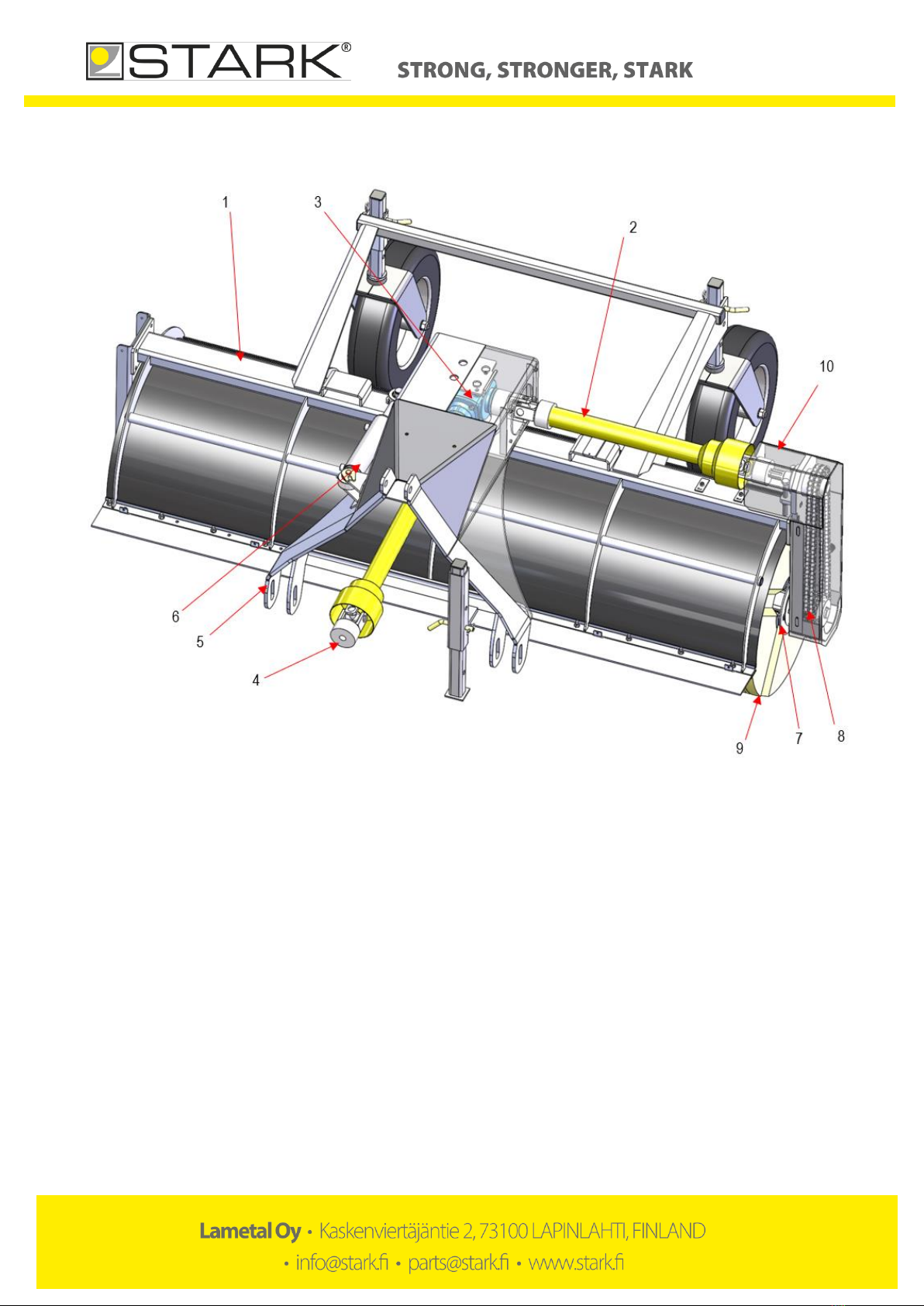
5. MAIN PARTS OF THE BACK BROOM .............................................................................................7
6. USING THE BACK BROOM.............................................................................................................8
6.1. Attaching the broom to the base machine........................................................................................ 8
7. OPERATING THE BACK BROOM ....................................................................................................9
7.1. Using the back broom........................................................................................................................ 9
7.2. Overload switch............................................................................................................................... 10
7.3. Changing the brush rings................................................................................................................. 11
7.4. Adjusting the chains ........................................................................................................................ 12
7.5. Removing the back broom from the base machine........................................................................ 13
7.6. Transferring the back broom........................................................................................................... 13
8. MAINTENANCE OF THE BACK BROOM .......................................................................................14
8.1. General safety precautions for the use and maintenance.............................................................. 14
8.2. Tightening torque............................................................................................................................ 14
8.3. Daily maintenance........................................................................................................................... 14
8.4. Maintenance after first 10 hours of operation ............................................................................... 14
8.5. Maintenance at 50-working hour intervals or on a weekly basis ................................................... 14
8.6. Lubrication points............................................................................................................................ 15
8.7. Adding oil to the angle gearbox....................................................................................................... 16
8.8. Propeller shafts................................................................................................................................ 17
9. HYDRAULICS................................................................................................................................18
10. WARRANTY POLICY .................................................................................................................20

Sivu 4 / 20
1. DECLARATION OF CONFORMITY
The original manufacturer’s EC declaration of conformity:
Generic product name: Back broom
Models: STARK THM 2500, THM 3000
Manufacturer:
Lametal Ltd
Kaskenviertäjäntie 2 73100 LAPINLAHTI, Finland
tel. +358 17 731 565
Declares that the above-mentioned equipment meets the provisions of Directive 2006/42/EC on machinery and, where
applicable, comply with the standards
•SFS-EN ISO 12100-1,
•SFS-EN ISO 12100-2
•SFS-EN 1050
The person authorized to compile technical documentation:
Lassi Mehtonen
Managing director
Kaskenviertäjäntie 2
73100 Lapinlahti, FINLAND

Sivu 5 / 20
2. PURPOSE OF USE
The back brooms are intended for sweeping of streets, yards and areas small and large.
3. SAFETY PRECAUTIONS
Make sure you know your equipment before you start using it. Equipment may be operated
only by an individual who is thoroughly familiar with its use.
Before connecting hydraulics to the base machine, make sure that:
-there is no-one between the attachment and the base machine
-the base machine is turned off and the parking brake is on.
When coupling the attachment to the base machine, make sure that:
-all locking cotters are intact and in order
-hydraulic hoses are intact
-there is no skin contact to hydraulic oil when connecting hydraulic hoses
-you do not to pull by the hydraulic hoses, but only by the hydraulic fitting.
During operation, pay attention to:
-safe, appropriate travel speed
-other traffic, people and animals
-danger zones and objects that block your view
-children
-use of turn signal when driving
NEVER use the machine, if there is someone in the danger zone
NEVER go under the attachment
WARNING! Rotating rollers!
During maintenance, the hydraulics of the base machine MUST be turned off. The base machine MUST also be turned
off and the parking brake MUST be applied. The equipment must be properly supported, if maintenance can only be
performed by going under the equipment. Never go under the equipment if it is not properly supported.
Daily maintenance:
-check general condition of structures, make repairs if needed
-check the hydraulic hoses and fittings, and replace damaged parts
After every 50 hours of operation:
-lubricate points specified in later section of this manual
-check all bolts and nuts for tightness
Check all bolts, nuts and hydraulic fittings for tightness after the first day of operation!
If the equipment is not likely to be used for a longer period of time, clean it thoroughly after use and lubricate as
instructed.
WARNING! Pressurized hydraulic hoses and components!

Sivu 6 / 20
4. IDENTIFICATION INFORMATION AND
SPAREPARTS
4.1. Identification plate
Identification plate is placed on the side of the equipment. The plate includes contact information, machine type, year of
manufacture, serial number and weight. (See an example of an identification plate in picture 1 below).
The first four numbers in the serial number indicate the month and year of manufacture (month first). The remaining five
numbers constitute the machine tracking number, which is stored in the manufacturer’s database (13971 in the example
below).
Picture 1. Identification plate
Take down the machine type and the serial number of your back broom:
Product and model _______________________________Serial number___________________________________
4.2. Maintenance services
When replacing parts, use original, manufacturer spare parts only. By using original spare parts, you ensure dependable
operation of the back broom and comply with the warranty policy. To facilitate the supply of spare parts, always inform
the manufacturer/retailer of the model and serial number of the back broom (marked in the identification plate) when you
order spare parts.
For more information on maintenance and spare parts, please contact the STARK maintenance and spare part services
or your retailer.
Contact information for STARK maintenance services:
tel. +358 (0)17 731 565, e-mail info@stark.fi
tel. +358 (0)44 758 6221, e-mail parts@stark.fi

Sivu 7 / 20
5. MAIN PARTS OF THE BACK BROOM
Picture 2. Main parts of the back broom
1) Back broom’s frame
2) Propeller shaft
3) Angle gear box
4) Front propeller shaft
5) Rotating triangle
6) Hydraulic cylinder
7) Broom roller
8) Chain
9) Brush ring
10) Chain’s protective plate

Sivu 8 / 20
6. USING THE BACK BROOM
When attaching the back broom for the first time, make sure it is compatible with the base machine by following the
instructions below. Always check the compatibility when attaching the back broom to a new base machine.
Make sure that the base machine allows the installation of the back broom. The back broom is attached to the base
machine’s rear lifter.
Minimum requirements of the base machine:
-3-point attachment
-2-action hydraulic valve for rotating the broom. Broom has ½” connectors.
-The broom is attached to 540 rpm outing by propeller shaft.
6.1. Attaching the broom to the base machine
The back broom is attached to the back of the base machine by 3-point attachments. The machine is connected to a
hydraulic system. Hydraulic circuit diagrams can be found in a later section in this manual.
Before using the back broom, MAKE SURE all locking cotters are secured and intact.
When coupling back broom to the base machine, please pay attention to the instructions on the use of the base
machine.
1. Make sure that the attachment and the base machine are compatible in terms of mechanical solutions, hydraulics and
electricity.
2. Make sure there is no pressure in the base machine hydraulic system. When connecting, always make sure the
hydraulic connectors are clean and the hoses are intact.
3. Reverse the base machine near the broom. Attach the support beams to the broom. Apply parking brake.
4. Back broom is attached to the coupler on the base machine. Attach the broom to the base machine. Make sure all the
cotters are locked.
5. Attach the propeller shaft the base machines power take-off (540 r/min). Make sure that the propeller shaft has its
protective covers in their proper places. Attach the hydraulic hoses.
6. Check carefully the attachment’s, the base machine’s and the fitting’s trajectory for collision. Make sure that the
needed space for hydraulic hoses and -attachments is adequate.
7. During first hours of operating the attachment, bolts, nuts and connectors might loosen up. Retighten them after the
first day of operating the attachment.

Sivu 9 / 20
7. OPERATING THE BACK BROOM
Check following before using the back broom:
-Broom is installed properly to the base machine
-All locking cotters are in place
-Hydraulic hoses are attached properly
-Hoses are intact
-There are no oil leaks in attachment
-All functions are in order
-Learn the functions of the back broom in an enclosed area before actual usage.
7.1. Using the back broom
1. Make sure that the attachment and the base machine are compatible in terms of mechanical solutions,
hydraulics and electricity.
2. The back broom is attached to the coupler on the base machine. Reverse the base machine near the broom.
Attach the support beams to the broom. Attach the back broom to the base machine, and make sure the
locking cotters are secured.
3. Turn off the base machine and make sure the parking brake is applied.
4. Make sure there is no pressure in the base machine hydraulic system. When connecting, always make sure the
hydraulic connectors are clean and the hoses are intact.
5. Lift back brooms front support legs. Lock them in upward position with locking cotters.
6. Check carefully the attachment’s, the base machine’s and the fitting’s trajectory for collision. Make sure that the
needed space for hydraulic hoses and -attachments is adequate.
7. Keep the back broom in suitable distance from ground (picture 3). Brush ring should bend approx. 20mm. Do
not press the broom too hard with a base machine. Brush rings wear down faster and the attachment could
be damaged!
8. The maximum rotational speed of the broom roller is 300 r/min. Gear ratio for the broom roller us 1:1,4
(retardant). Adjust the power out-take (540 r/min) and the engine’s rotational speed so that the max. rotational
speed of the broom roller is not exceeded.
9. Adjust the driving speed and the rotational speed of the broom appropriate for the amount of sand / trash.
10. Back brooms horizontal propeller shafts are equipped with overload switch. Their max. torque is 900 Nm. It is
forbidden to replace to overload switch with a stronger torque switch.
11. Stay alert for any abnormal behaviour and oil leaks also during driving.

Sivu 10 / 20
Picture 3. Suitable height for the brush ring
7.2. Overload switch
Load on the back broom must be reduced when the overload switch opens. Slow down the driving speed or stop
completely until the overload switch operates normally. Overload switch is a safety mechanism which can be damaged
when used incorrectly. Warranty does not cover propeller shaft equipped with overload switch. (Picture 4)
Picture 4. Overload switch

Sivu 11 / 20
7.3. Changing the brush rings
1) Detach the protective case. (Picture 5)
2) Loosen the chain and remove it. (Picture 6)
3) Detach broom rollers bolts from the other side. (Picture 7)
4) Detach the bearing’s bolts (2 pc) and socket screws from the bearing. (Picture 8)
5) Remove the end plate located under the bearing by removing the bolts. (Picture 9)
6) Remove brush rings. When installing new brush rings, turn them 180° if needed, so that the spikes of the rings
are evenly placed, and the rings don’t have large gaps between them.
7) Make sure, that the spikes of the rings don’t touch the chain.
8) Assemble broom roller in reverse order. It is recommended to add copper paste or similar lubricant between the
bearing and the broom rollers axle. This prevents the axle to get stuck. Tighten the chain to suitable tightness.
Picture 5. Remove the protective case Picture 6. Loosen and remove the chain and bolts
Picture 7. Remove the bolts Picture 8. Remove the bearing unit

Sivu 12 / 20
Picture 9. Changing the brush rings
7.4. Adjusting the chains
The back broom has a chain at right side, which transfers the power between the propeller shaft and the broom roller’s
axle. Check chains for tightness after every 50 operating hours. If chains are too loose, they will be needlessly strained.
If chains are too tight, they will strain cogwheels and axle’s bearings.
Chains are behind their protective cases. Adjusting the chains:
1. Remove the protective case.
2. Loosen 4 bolts in a bearing plate (picture 10).
3. Adjust the chain by tightening / loosening the bolts (picture 11).
4. Suitable tightness for the chain: press the chain in the middle with a force of a approx. 20 kg. Chain should yield
about 10-15 mm (picture 11).
5. Tighten the locking bolts and reattach the protective case.
Picture 10. Bolts of the bearing plate Picture 11. Adjustment bolts

Sivu 13 / 20
7.5. Removing the back broom from the base machine
1. Lower the back broom down on an even surface on its support legs (picture 12).
2. Adjust the support wheels so that the brush rings don’t touch the ground.
3. Turn off the base machine, apply the parking brake and depressurize the system.
4. Detach the hydraulic hoses and protect hose ends with plugs.
5. Unlock the coupling mechanism and detach the device.
6. If the equipment is not likely to be used for a longer period of time, clean it thoroughly after operating and
lubricate as instructed. Remove water from irrigation system’s hoses. If possible, store the unit inside.
Picture 12. Properly supported back broom
7.6. Transferring the back broom
When transferring the attachment lift the brush rings and the support legs and reduce the speed if needed, especially on
bumpy, uneven roads. Base machine or the attachment can be damaged due to excessive speed.

Sivu 14 / 20
8. MAINTENANCE OF THE BACK BROOM
8.1. General safety precautions for the use and maintenance
-Comply with existing laws and regulations and the instructions given in this manual.
-Never go under an unsecured device.
-Always apply the parking brake of the base machine before performing any actions on the device.
-Only use tools that are in proper working order.
-Be careful with the pressurized hydraulic hoses and components.
-Make sure there is no pressure in the hydraulic system. Take into account the pressure accumulator.
-Make sure hydraulic fluids or greases do not leak to the ground.
-Use all necessary personal protectors.
8.2. Tightening torque
Nm (strength 8.8)
M4
3,3
M5
6,5
M6
11,3
M8
27,3
M10
54
M12
93
M14
148
M16
230
M18
329
M20
464
M22
634
M24
798
M27
1176
M30
1597
M33
2161
M36
2778
M39
3597
Table 1. Tightening torque
8.3. Daily maintenance
In order to prevent further damages, it is important to inspect the device visually for possible defects. Inspect at least the
following daily:
-Hydraulic hoses and components for possible leaks
-General mechanical functioning
8.4. Maintenance after first 10 hours of operation
-Lubricate, preferably with a NLGI-2 grease or equivalent (see instructions in later sections)
-Check all bolts and nuts for tightness (table 1)
8.5. Maintenance at 50-working hour intervals or on a weekly
basis
-Lubricate, preferably with a NLGI-2 grease or equivalent (see instructions in later sections)
-Check the mechanical condition of the device for bends, distortions or breaches
-Check fastening bolts for tightness (table 1)
-Check the chain for tightness (section 7.4.)
-Lubricate the propeller shaft (section 8.8.)

Sivu 15 / 20
8.6. Lubrication points
1. Grease nipples for the broom roller’s bearing (at both ends)
2. Grease nipples for the hydraulic cylinder
3. Grease nipples for the support wheels (at both wheels)
4. Grease nipples for the bearing at the top of the chain
5. Grease nipples for the propeller shaft’s grating (detailed instructions at section 8.8.)
Picture 13. Lubrication points Picture 14. Lubrication points
Picture 15. Lubrication points

Sivu 16 / 20
8.7. Adding oil to the angle gearbox
The angle gearbox in the middle has oil inside. The oil is checked and changed using the dip stick that is located behind
the cover box (picture 16). When the device is horizontal the oil level must be at least level with the minimum level
shown on the dip stick.
You can access the plug of the box by detaching the protective sheet behind the box, which is attached by four M10
bolts.
The oil type used in the case: Gear oil (Viscosity 80W-90, API GL-4 classification). Amount of oil 0.8 liters. You must
perform oil change every 2,500 hours, or at least every 5 years.
Picture 16. Angle gearbox

Sivu 17 / 20
8.8. Propeller shafts
The back broom has two propeller shafts (picture 17). Shaft’s grating must be lubricated after every 8 operating hours.
Add grease to the grating until it starts to pour out. (Picture 18)
Propeller shaft’s shape tubes need to be greased regularly, after every 50 operating hours. Vaseline spray is suitable for
greasing (for example Würth HHS2000 or similar).
Picture 17. Propeller shafts
Picture 18. Grader of the propeller shaft

Sivu 18 / 20
9. HYDRAULICS
The back broom can be connected in two different ways, either with two (figure 1) or four (figure 2) hoses. When
connecting with two hoses, the hydraulics of the basic machine is connected to quick connectors and a separate switch
is used to choose whether the broom is rotated or turned. When connecting with four hoses, a rotation cylinder and the
rolling of the engine are connected separately to the hydraulics of the basic machine. This means that the lifting and
rotating of the broom can be done with the hydraulics of the basic machine, and no separate control valve is needed.
The rotation speed of the broom is adjusted with the valve shown on figure 1. The suitable position is usually found
between 5 and 8. If there is a flow controller in the basic machine, the speed control valve can be set to position 10.
SH = Cylinder hydraulics MH = Motor hydraulics
Figure 1. 2-hose hydraulics

Sivu 19 / 20
Figure 2. 4-hose hydraulics

Sivu 20 / 20
10. WARRANTY POLICY
1. Warranty coverage
Lametal Oy, the manufacturer of STARK attachments, offers new devices a guarantee which covers material
and manufacturing defects in accordance with the terms in this warranty policy. Limitations to the warranty are
specified in point 7.
2. Warranty starting date
The warranty starts on the agreed date of product delivery to the client, or on the date of approved instalment or
on the date the equipment has been taken into operation. The equipment is taken into operation when it has
been delivered to the client in accordance with the agreement and the client has acknowledged receipt of the
equipment. The client is to check the equipment before use as instructed in this manual and to notify the
manufacturer or the reseller of the equipment of any defects or flaws that are noticed during initial inspection.
This notification is to be done in writing within eight (8) days after delivery. Hidden defects and defects that are
otherwise difficult to detect must be reported immediately after detecting them, within one (1) year after receipt
of the equipment at the latest.
3. Warranty period
STARK warranty covers a period of one (1) year. If need be, the client and the manufacturer make separate
agreements on warranty concerning repairs and spare parts used in repairs.
4. Repairs during the warranty period
Repairs during the warranty period are carried out free of charge within the normal working hours by the
manufacturer repair and maintenance services or by a repair service provider accredited by the manufacturer. If
repairs are carried out by a repair service provider which has not been accredited by the manufacturer, the
manufacturer does not compensate for costs that are not covered by the warranty, such as travel and waiting
hours, daily allowances, travel expenses or costs arising from detaching and reinstalling the equipment. The
manufacturer does not compensate for indirect costs caused by repairs during the warranty period, such as lost
working hours. Original parts replaced during the warranty period shall remain with the manufacturer. The client
must keep the damaged parts for six (6) months unless otherwise agreed, and have them delivered to the
manufacturer without delay upon request.
5. Conditions for repair under warranty
Manufacturer’s instructions for operation, instalment and maintenance have been followed.
The equipment was damaged when operated in conditions for which it has been engineered.
In maintenance and repairs, only original, manufacturer parts have been used.
The form for the notification of defects provided by the manufacturer or the retailer has been filled in according
to the instructions and submitted for processing.
6. Warranty after repair
Warranty holds until the end of the original warranty period. Repair under warranty does not prolong the
warranty period.
7. Limitation to the warranty
The warranty does not cover:
oconsequential expenses resulting from the damaged equipment
oindirect costs, such as loss of working hours
odamages caused to a third party
oequipment or components that have been modified or repaired by the client themselves
odamages caused by normal wear and tear, inappropriate maintenance operations, neglect, accident,
connecting error, equipment overloading, user’s inexperience or use of other than original parts
The warranty offered by the manufacturer does not exceed the purchase price of the equipment.
8. Warranty claim procedure
For a warranty claim to be processed, the form for the notification of defects provided by the manufacturer or
the retailer must be filled in according to the instructions and submitted for processor. The warranty claim
procedure is carried out either in Finnish or English.
This manual suits for next models
1
Table of contents
Popular Cleaning Equipment manuals by other brands

Kärcher
Kärcher FC 7 Cordless quick start guide

Bieffe
Bieffe STIR PLUS Use and maintenance manual

Caviblaster
Caviblaster 0625-G Operation & maintenance manual

Blastrac
Blastrac 2-30DS Global operating instructions

Krüger Technology
Krüger Technology KGVG 18000 instruction manual

Streamline
Streamline STREAFMLO 25 instruction manual