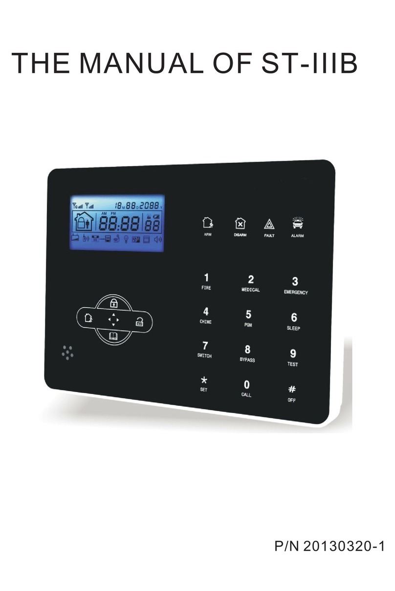
foc.us ST-IIIB User manual

P/N 20130320-1
THE MANUAL OF ST-IIIB


Brief
Thank you for
purchasing
the
"smart
home"
products
of
our
company,
thank
you
again,
we hope
our
products
can
bring
convenience and
protection
for
your
safety!
The
"smart
home" system uses the most advanced digital sensing
and control technology, it is a set
of
smart
alarm control system
of
anti-theft, anti-fire, and anti-gas leak compatible with
wired
and
wireless alarm. This
product
is
easy
to operate
and
easy to learn with
voice indication all
around
the operation, complicated orders are
not
needed.
The
"smart
home" system recommends the most advanced multi-
random
vault
technology in safety and reliability,
which
effectively
solve the
problem
of
interference, false positives, false negatives
that
cannot
be
solved
by
similar
system
at
present. The
way
the
"smart
home"
system uses
in
the
alarm
signal
on
the common
high-speed
way
CONTACT ID makes application
of
this series
of
products wider
and compatibility stronger. The system can be widely used in family,
community, villas, shops, units and so on.
We recommend
that
you carefully
read
the instruction to facilitate
you
for a skilled operation and use to the product, so
the
product
can
better
serveyou.
We
will
not
notice
if
there
is
a
change
of
product
performance,
if
you
want
to
know
the
latest
features,
please
contact
with
the
relevant
business.

i4i§i
..
fi,llfl•
Content
ChapterI Introduction····
·············
·
········
······
········
·
·············
·········· 1
Chapter2 Installation and Connection ····· ·
········
····· ······ ··
············
4
2.1 Installation · · ·· · · ·· · · ··········
··
··························· 4
2.2 Connection(N.O. N.C)·······
····
······
··
···········
····
··········
····
······-4
2.3
Install wired detector ·······
····
······
··
··
····
···················
····
······· 4
2.4 lntall wereless
detector··································
·
··················
5
Chapter 3 Keypad and operation
..........
.
......................................
5
3.1
About
panel······················································
·
··············
5
3.2 Basic
operation·····················
····················
····
··········
····
·····7
3.3 Flasheswhen phone line
cut
···········
·
·································
7
3.4 Hostarm and disarm ·· · · ········································· 8
3.5Alarm
procedure··········································
·
··················
1O
Chapter IV Voice alarm receiving ······· ······ ·············· ··
··
·· ·········-
11
and GSM control
4.1
Remote phone control ···············
··
····················
··
··············
·11
4.2Alarm receiving phone
operation······
·
·············
·
··················
-11
4.3 GSM remote operation
.............................................
.
......
-12
4.4 GSM alarm
receiving························································12
4.5 GSM control via SMS ······················································
·12
Chapter IVVoicealarm receiving and GSM control ························
~
3
5.1
Set
system clock
····························································13
5.2
Set
userpassword
······
·
····································
·
··············13
5.3
Set
voice phone · ·····················
··
············
··
················ · 13
ChapterVI System Setting ·· ·················································· 14
6
.1
Set
password···
·············
·
········
······
········
·
·············
·
········
····14
6.2
Set
CMS number·····
·············
·
·············
·
········
·
·············
······15
6.3
Set
voice phone····
·············
·
········
······
········
·
·············
·
········
16
6.4
Set
system options
....................................................
17
6.4.1
Set
system
clock······························
·
·······················17

6.4.2 Set
entry
delay · 18
6.4.3 Se!
exit
delay 18
6.4.4 Se! siren time 18
6.4.5 Set ring
limes
18
6.4.6 Se!
detector
loss inspection · · · ·
··
· 19
6.4.7Selarmldisarmlone
19
6.4.8 Setarm/disarm report 20
6.4.9 Set others
·····························································
20
6.4.9.
1Set
emergency alarm siren type 20
6.4.9.2
Ac
off
inspection time
selling
21
6.4.9.3 Magneticcontact inspection
6.4.9.4 Checkwireless
detector
tamper
21
...
21
6.4.9.5
Setforce
arm···················································
21
6.4.9.6 Settelehpone line disconnect remind 22
6.4.9.7 Setzone alrm
times··········································
22
6.4.9.8 Set listen-in time 22
6.4.9.9 Set
AC
off
remind
·············································
23
6.5 Manage wireless device 23
6.5.1
Set
remote control
··················································
23
6.5.
1.
1 Enroll remote control·· · ·23
6.5.1
.2 Enterremote control code·
6.5.1.3 Delle remote control · 24
.....
24
6.5.2
Set
detector ····················
··
·········
··
·········
··
·········
··
··· 24
6.5.2.1 Detectorcoding
6.5.2.2 Enter
detector
code
6.5.2.3 Delete
detector.
6.5.3
Set
appliance switch
24
...
25
25
25
6.5.3.1 Enroll appliance switch
·····································
25
6.5.3.2 Delete appliance switch
····································
26
6.5.4 Enroll wireless
siren···············································
26
6.5.4.1 Enroll wireless siren ·
6.5.4.2 Delete wireless siren
6.6.5
Set
doorbell ·
26
26
..
27
6.5.5.1Enroll doorbell
·················································
27
6.5.5.2 Delete doorbell ·
..
27

6.6.1 Set zone
attribution·
6.6.2 Set zone siren
type
·
6.6.3 Setwired zone loop
type
6.6.4 Setwired zone response speed
6.6.5 Set related zone
6.7 System maintance
6.7.1
Set
timing operation
6.7.2 Recording ·
6.7.3
Play
recording
6.7.4
Set
programmable output
port
6.7.5 Delete system
events
.
28
.
28
28
. 29
29
30
31
31
31
...
31
. 32
6.7.6 Restore to
factory
default
32
6.8 SetGSM module 32
6.9Advanced setting options
6.9.1 GPRS enable and disable 34
35
6.9.2
Set
sever
IP address 35
6.9.3
Set
sever
port
36
6.9.4
Set
user
ID · · · 36
6.9.5
Set
user
password 36
6.9.6 GSM SMS language 36
6.9.7 Delay
zone
tone source options ···
······
···
······
··· ······37
6.9.8 Handshaketone input signal
intensity
37
6.9.9 DTMF
output
signal
intensity
37
6.9.1O
Set
LCD standby brightness 37
6.9.11 Alarm
event
retain
time
Chapter
VII technical specification
7.1 General
data
·
7.2 Physical performance
.
38
39
. 39
. 39
Chapter
VIII maintenance · · 40
8.1
Regular
test
·································································
40
8.2 The cleanliness
of
control main machine 40
ChaplerVX
limitation
of
the products 40

''fJ§i11fl.ll6'9tt
Chapter
Introduction
1.
1
Function
Introduction
I,
Alarm
mode: with PSTN and GSM networkalarm, GSM networkwith
GPRSfunction(GPRS function is
for
China marketonly), remote arm and
disarm panel through CMS
or
SMS CID protocol, SMS notification, the
priority
of
PSTN and GSM networkis Optional.
2,
With a
new
large-screen, full-touch buttons, LCD graphic
display
steps,
work
status.Alarm process easyand intuitive.
3,
The full Englishvoice prompting operation: all local
or
remote operation,
alarm information,
event
log view.
4, GSM-hookand
voice
telephone with intercom function.
5,
All
alarm informationcan be programmed
for
the
following settings:
0 does notsend
any
information
1,SendonlySMS
2,0nly
call users 3,SMS
+call
user
4, CMS only
5 ,CMS +SMS. 6,CMS
+call
user 7. CMS +SMS
+call
user
6,
Sleepmode: Under
sleep
mode, all the lights, backlight, voice and
remind tone are disabled.
7,
Alarm
panel
under
idle status is
equivalent
to a cellphone, you can call
through the GSM network
for
balance inquiries
8,
The associated zone: 4 groupsassociated zone, three kinds
of
association patterns, can
effectively
reducefalse alarm
or
for
other
functions.
9,
PGM output: With a programmed output port, followed
by
five kinds
of
alarm eventsoutput.
1
Q,
The doorbell Audio Optional:
1.
Ding Dong
2Welcome
3. Recording 4.
Dee-Dee-
11,
Remote phone operation: dialing by telephone offsite,
after
password
verification, you can arm, disarm, listen-in premise, system status query
and electricalswitches controls and
other
operations.
12,
VoiceAlarm: When panel alarm, it will automatically dial
the
preset
user
phone numbers
to
report alarm informationthen you can remote control
the
panel
after
enter
user
passwords.
.,

i4i§i
..
fi,llfl•
13,
Wireless zones, each wireless zone can automatically learn
the
codes
or
be
coded manuallyvia the keyboard.
14,
8 wired zones, Usercan
set
the
circuit
type
and speed
of
response, supportN.O, N.C.
15,
Enableenroll total Bwireless remote,B
electronic
switch,1
pc
of
wirele-
ss doorbell and Unlimited
for
quantity
of
one
way
wireless siren.
16,
Follow
me
phone
#,two
for
CMS,four
for
private alarm receiving.
17,
Status inspectionfunction:Enable record and inquiry 120 alarm
event
messages.Like the time when happensanti-tam
per
alarm,detectoralarm,
tel-line
off,arm,disarm,system setting,battery
low
volt
age
etc.And also
can
inquiry
the
zone
number
and alarm type.
18,
Timing
arm
and disarm: 4 sets
of
timing arm and disarmtime.
19
, Electrical switchescontrol:
User
can remote switch
on/off
via phone
or
SMS, also can be controlled manuallythrough
the
localalarm panel.
20, Zone programmable: factory
preset
for
each zonetype. Users
can modify
all
the zone type according to the actual
needs.
21
, Clock: Built-in full automatic
calendar
clock,
set
to
local
time
consistent
22,
Password access management:
the
panel has
one
administrator
password 16
user
password, The
administrator
password primarily
for
system administrators
to
set
up
the alarm system; The
user
passwords
for
users in
the
day-to-day use such
arm/
disarm.remote operation. The
administrator password,
user
password can be
freely
modified.
23,
For
CMS networking alarm, depending on the number
of
users,
the
user
can
set
four,
six
or
eight
user
codes(account number).
24, Zone type identification:Afteran alarm is triggered,
the
alarm zone
number
displayed on
the
LCD screen
of
the
panel, also can send the
detailed report to CMS which includesalarm locations and zone types.
25,
Al-prooffunction:lf
try
to cut
off
the
wire between wered detectorand
panel
or
cut
off
the tel line which.

14141
..
m,t•fl•
26,
The tampering alarm:
cut
the
cablebetween wired detectors and
the
panel
will
trigger
larm,
the
telephone line cutwill
automatically
trigger
sirenalarm.
When someone deliberatelydismantled
the
panel, itwill alarm when
triggering
tamper
switch
at
the
back
of
the
panel.
27
, Timing armfdisarm:Enable set4 group time armfdisarm time.
28
, CMS communications test:
The
panelwill send a message to CMS
at
the
pre-settime interval to inspectthe communicaiton
if
normal.
29
,
Siren
options:Built-in siren, external wired siren,
Wirelss
siren. All sirens
can be programmed
as
enabled/disbalewhen alarms.
30
, The
voice
speaker
volume adjustment:
adjust
the volume by a rotary
switch on
the
panel.
31, Wireless repeaterfunction:can extend
the
distance between
the
detector
and
the
panel by addinga wireless repeater
of
our
company.
32
, Thewireless
detector
low
battery prompted:Detectorswill send status
reportto the panel
every
1-3
hours,
the
corresponding zone
number
and
the
battery
voltage
symbol will be displayed on
the
LCD screen and also
will reportto CMS.

1414
Chapter
2 Installation and Connection
2.1
Installation
1.Fixthe bracket to
the
wall
and hang the
Panel
to
the
bracket
2.
The
large
metal objectscan not be placed around
the
panel,
so
as not
to
affect the wireless signal.
3.Make sure
to
place
the
panel within
the
wireless range
of
all wireless
accessorisand
pay
attention to
the
hidden
2.2 Connection(N.O. N.C)
As
pictures
N.C
N.O
ND
PGM GND Z33
Z34
GND Z35 Z36
Z37
Z38 GND
Z39
Z40
DC15V/2A
Power
LINE
~
TELL
! 0
Voice
volume
knobs
Here
only
introduce
the
zone
33,
34,
37,
38.
The
other
zones
please
refer
to
the above.
2.3 Install wired detector
2.3.1The wired
zones
is disabledfactorydefault.
when
to
use
wired zones
please enable
the
zones
firstly.When wired zones is in trouble,
the
panel will voice prompt"operation fails, Zone
trouble"
if
users try

14141
..
fi.ii@n•.,,
To
arm the panel. Thezone numberwill be also displayon the LCD
screen.
At
this
time arm system
is
not
allowed unless you force arm.
2.3.2 The control pane can power 15V, 1
OOmA
to
detectors.
The
max curent
is 1
OOmA.
Do notexceed 1
OOmA,
otherwise please use extra power
supply.
2.4
Install wireless detector
2.4.1 As the
detector's
manual says,install coded detectorin the area 150m
from the control panel.Please
test
and makesure detectorcan
work
with
control panel normally.
2.4.2 Wireless repeaterfunction:when wireless detector
is
too
far
from the
panel
or
some occluders between panel and
detector
which disablethe
panel receivethe signal from wirelessdetector.Nowyou can choose
our
madewireless repeater
to
achievewireless signal relaytrans milting.

l!t1§111
fi,ii@ihr
Arm led:
Light
on underarmed status,
Light
flashes understaystatus.
Disarm led: Lighton
under
disarmed
status
Trouble led:
Light
on when with
zone
trouble. Lightflasheswhen
AC
cut.
Alarm led:
Lightflashes
when alarm.
~
Press 3 seconds
to
tirgger
fire alarm
Press 3 seconds
for
medical help
Press 3 seconds
for
SOS
Press 3 secondsthen
enter
user
code
to
enable
or
disable
delay
zone doorbell(
Refer
to
page
36)
Press 3 secondsthen
enter
user
code
to
enable
or
disable PGM
output(
referto page
30)
Press 3 seconds
to
enter
or
exit
sleep mode.
[I]
, Press 3 secondsthen
enter
user
code
to
enable
or
disable
eletrical switch.
: Press 3 secondsthen
enter
user
code
to
bypass zones
or
activate zones.
Press 3 secondsthen
enter
user
code
to
proceed normal testing,
siren testing and
walk
testing.
Press 3 seconds
to
make phone call through GSM, the longest
talk
time
is 240 seconds. the call will be interrupted when alarm
occurs.
Sleep mode: all led indicators, backlight, voice, remind tone will
be
disabled
under
sleep
mode, The panel will
exit
sleep mode automaticallywhen users
enter
system setting
or
when alarm occurs.
Bypass zone: bypassed
zones
means zonesdisabled.The bypass will be
restored when users disarmsystems
under
home
armed
or
armed status.
Communication test: To
test
the
communication between
the
panel and
the
CMS
if
normally
Siren test: to
test
if
siren working normal
Walk test:
to
test
if
the
detectors
are
working normallywith
the
panel and alarm

lib§
I
..
fl.ii
fl....,
3.2
Basic
operation
Factory
default
Adminitratorpassword: 012345
16 User passwords, NO.
01
factory
default
is 1234. No. 02-16
of
the
user
password
is
blankand can
not
enter
the usersetting untill
user
set
the
password.
Disarm:
User
password[1234]+DISARM
Home arm: Home arm
key
Arm:Arm key
Event log:
inquiry
key
Shutdown operation:
AC
power-off
state
{[~J
press
and hold
for
more than 3
seconds)+
user
password
[1234]+[!]
Entersystem setting:
[!]press
and hold
for
morethan 3 seconds+
adminstrator
password
[012345]+[!]
Enter usersetting:
[!]
Press and hold
for
more than 3 seconds+
user
NO.
(01)
+user
password(1234)+[!]
Zone inspection: Notinsepctwired zoneswithin one minutes
of
panel
power
up
Password reset: Enter000000
to
enter
system setting menu within one
minute
of
panel
power
up.
3.3 Flasheswhen
phone
line cut.
Light
on
when
phone
line
is normal.
Icon
Meaning
Icon Meaning
t,,11
GSM signal strength
~~
GSM is enabled
[]
Telephone line
@r
~
Leftbehind
CJ
Detector
low
battery @ Disarm
u PANEL
low
battery
l@
Arm
tlL(
,, Alarm
[~
eeftl
..
··S
Enable GPRS
tJ)»
Voice prompts "

iuj§
I
..
;;,;
'Vi.,.,
c
~
Flasheswhen phonelinecut. Lighton when phone line isnormal.
~
~
Flasheswhen GSM notready, Light on when GSM is normal.
1511····!i!
Flashes when GPRS disconnected with CMS. Light
on
when GPRSis
connected well with CMS.
c:J»)
Flashes undersleep mode. Lighton udernormal working mode.
A-DS
Zone5alarm
F-
DS
E Zone 5 trouble
P-DS Zone 5bypass
F-DSL Zone 5 detectorlost
F-QS
c:J
Zone 5
low
battery
The alarm zonenumberwill still be displayed
on
LCD screen
after
first disarm
when alarm accurs, returned
to
normal screen displayonlyusers disarm twice.
3.4 Hostarm and disarm
'kArm
l@IOB:OOI
SS I
Press the key
for
arm
away
on remote
or
the
keypad,then you hear"system
armed.please
exit
the protection area"
there will
be
"Dee-deen
sound to
confirm thesystem is armed
successfully.
IGDfOB:OOI
SS I
Press thedisarm keyon the remote
or
enter
your
user
password onthe
keypad,then you will hear"dee"and
voice"systemdisarmed",then you have
disarm successfully.

10..li!oi!Dlcv
l©irlOB:OOI
SS
I
Press thekey
for
home arm on the
remote
or
"HOME"keyon thekeypad,
then you will hearn system
stay·
And
it
displayhome arm icon
on
the
LCD screen.
lc
..
li!oi!Dli!v
IGDI
A-oolt!
I
Press the panicbutton on remoter,or
press"[!]
·key
on panel for3
seconds.
The codes
of
arm/disarm viadifferent ways:
Arm/disarm via keyfobs: 1-8 keyfobs----#40-47
Arm/disarm via
user
codes:
1-16
user
codes---#01-16
Arm/disarm via phone call: 1-4 userphonenumber---#60-63
Arm/disarm via CMS:
#97
Arm/disarm via home arm
key
or
arm
key
in panel:
#98
Auto arm/dsiarm
via
auto
timer
or
key
zone: #99

产品手册
1st 2nd 3rd 4th

UM4""1·"6'""'
Chapter IV Voice alarm receiving
and
GSM control
4.1
Remote
phone
control
Usercan
remote
control
the
system
by
phone
ca
II.
after
the
preset
ringing
times
then
panel
will
off
hook
the
phone
then
enter
the
4
digit
user
codes
according
to
voice
prompting
and operate as
per
the
voice
prompting.
Telephone
lin~
iii
~
User call landline
phones
Thephone rings
is
7
times,
after
7
times
ring
the
panel
will
off-hook
automatically.
Please
enter
password
@
ITJ0me±J
+ +
Then
enter
user
code according
to
voice
prompting(
the
factory
default
user
code
is 1234)
--~
Press 1
to
arm
system
Press 2
to
disarm
system
Press 3
to
Stay arm
@
Press 4
to
check
system
status
Press 5
to
appliance
switch
contra
Press 6
to
control programmable
output
port
Press
Oto
Disconnect
4.2
Alarm
receiving
phone
operation
When
alram,
the
panel
will
dial
the
pre-set
voice
phone number,
when
the
user
pickup
the
cal
I,
they
will
hear
the
voice
prompting
as
below,
if
not
press 1
to
cancel
the
alarm
or
press 4
to
disarm
the
system,
after
off-hook,
the
panel
will
call
other
preset
voice
phone
numbers.
«(liil>»<D
..
~
(l)
..
Thepanel
will
dial
the
preset
voice
The user
pick
up
phone
number
the
call
when
alarm
occur;
~~~~~~~~~~~~~~
..lll)i\\
Play
the
recorded voice
messa!@
"Ill!!/
first,
then:
Press 1
to
cancel alarm
Press 2
to
check
alarm
event
Press 3
to
arm
system
Press 4
to
disarm
system
Press 5
to
Stay arm
Press 6
to
enablesiren
Press 7
to
listen-in
Press 8
to
control
programmable
output
port
Press 0
to
Disconnect

4.3 GSM remote operation
(talk-back
function added)
When alarm occurs, GSM will call the
preset
voice number, when
pick
up
the
call.enter
4
digit
user
code, then
voice
prompt: Press 1 to arm system,
Press 2 to disarm system, Press 3 to Stayarm, Press 4
lo
check
system
status, Press 5 to
appliance
switch control, Press 9 to talk-back, Press 0 to
Disconnect.
4.4 GSM alarm receiving (talk-back function added)
When alarm occurs,
it
will send SMS first, then call the preset voice number,
when
pick
up the call,
ii
will play the recorded voice message first, then voice
prompt: Press1 to cancel alarm, Press 2 to check alarm event, Press 3 to arm
system.Press 4 to disarm system, Press 5
lo
Stay
arm, Press 6
lo
enable siren,
Press 7 to listen-in, Press 8 to
control
programmable output port, Press 9 to
talk-back, Press 0 to Disconnect.
4.5 GSM control via SMS
Arm command:
password:f234syslemarml
Disamrcommand:
password:1234 system disarm
Slay
command:
password:i234systemtlome
Cancel alarm command:
[pass,.,ord:123~systelTlcanc<!iJ
Status checking command: I password:1234 system
status]
Enable programmable
output
portcommand:
lllaswoiiEf234pgmopen
I
Disable programmable
output
portcommand:. password:1234 pgm
close.
Enable appliance switch command:
switch
Disable appliance switch command:
•password:1234 switch close
X(X=1-8
on
behalf
ofappliance
switch number)•
Setapn:
• password:1234
apn:"aaa·
Set
ID:
cpassword:T234usero"l:il:>I:>"
Set
password: I password:1234 pwd:
"ccc"
Note: the
factory
default
user
code is 1234, when arm successfully, SMS auto
reply"
arm
successfully"
,
if
the password is correct,
the
command is not
correct, SMS will
reply"
operation
failure"
,
ifthe
password is
not
correct,
no SMS reply.

141§1
..
fiilifl..,,
Chapter
IV
Voice alarm receiving
and GSM control
Press[*]
for
3 seconds
Ill
LlJ
Set
system clock
G +
OJ~[]]@]
+
[1J
_.
Set
userpassword
Set
voicephone
5.1
Set
system clock
Forexample:
set
system clock as :22:59:3622/12/2012
Press[*]
for
3 seconds
GJ
•I
~~Enterpassord
I+
[!][!][!]8]
+[!]+[!_][!]
-.
...
Pleaseentersystem
clock, pressconfirm +
l.jl
121
+
l.jl
121
+
121121
+
121121
keytosave,press
L!J~ L!J~
~~ ~~
back key toexit. Y M D H
+
mm
+
mm
+
oo
Min
Sec
on
screen
According
to
flash ofY.M.
D.
H.Min.Secon screen, enter12.12.22.22.59.36
by
turn, also can press [UP] [DOWN] key to move cursor.
5.2
Set
user
password
Forexample:
Set
No.16 user pasword
as
5678
Press[*]
for
3 seconds
GJ
-.1
~~Enter
passord
I+
[I][!]
[1J
GJ
+
~
+
[!]
~
_.
~~Please
enter
theserial number
'4~
Enterpassword, press
of
your
modified password, + m
m+
00
.. confirm key
to
save,
confirm keytoconfirm,press press backkey
to
exit.
backkeyto exit.
Note: Can
set
16 userpasswords, corresponding password No. from
01
to
16,
OnlyNo.1 password can enterusersetting.
5.3
Set
voice phone (referto page 15)

Chapter
VI
System Setting
Press[*]
for
3 seconds
G +
[QJDJ[l]l:fil~lID
+
[!]
_.
6.1 Setpassword
Press[*]
for
3 seconds
[]
Set password
[lJ Set CMS number
@]
Setvoice phone
~
Setsystem options
[]]
Setwirelessdevices
~
Setzone
l1J
System maintenance
8
SetGSM
[£] Setadvanced options
G +
[QJ[IJ[l]@J@J[]J
+~+OJ~
Then
operate
according to
the
--~
[1]SetAdmin password
[]
[!]
'4~
Enter
password,
press confirm
key
to
save,
press back key to exit.
-.:$The setting
is
saved
Setpassword voice promptas below.
'4j)
[2]Set userpassword
[lJ
[!]
'4:$
Please
enter
the serial number
of
your
modified password, confirm
key to confirm, press back
key
to
exit
pressconfirm keytosave,
'4lJ
Enterpassword,press
confrim keyto save,
Press backkey
to
exit
1-.JJ
Thesetting
is
savedj
Note:
1.passwordsettinginclude
"userpassword"
and
"administratorpassword",
user
passwordmainly use todisarm the system,
it
isa private
key
forremote
controlling, "administratorpassword"
is
thesolepasswordto setthe system.
Other manuals for ST-IIIB
2
Table of contents
Other foc.us Security System manuals
Popular Security System manuals by other brands

Bosch
Bosch ITS-SPDIAL-FR installation manual

ADEMCO
ADEMCO Vista 4140XMPT user manual

EmerCom Technologies
EmerCom Technologies EMC-PAC user guide

ABB
ABB Arc Guard System TVOC-2 Installation and maintenance guide

SecurView
SecurView CVR V3 Series System guide

Nedap
Nedap Smartcard-Booster LEGIC installation guide