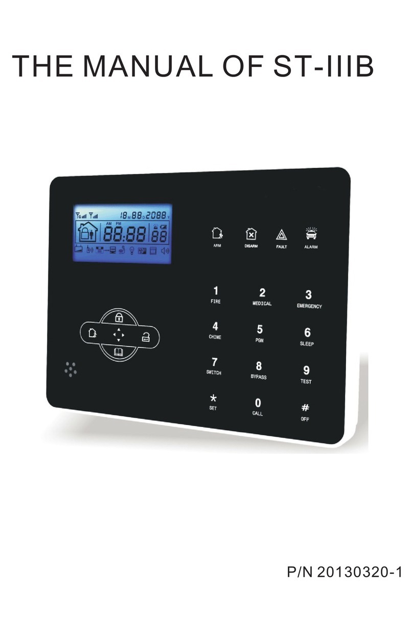
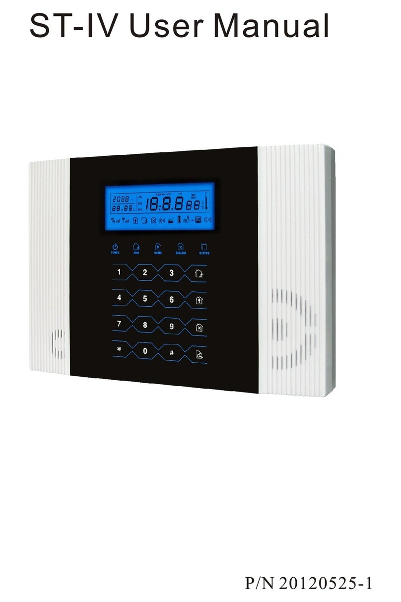
foc.us FC-7564 User manual

FC-7564 user manual
P/N 20120815-A
DISARM
ARM
POWER
COM
ALARM
FAULT


13VAC 2A
2.2K 2.2K
+BELL- GND GND
A
KEY+ GND Z1 Z7 Z8
Z2 Z3 Z4 Z5 Z6
AC AC TX RX +12V B
GND GND GND
GSM
2.2K 2.2K 2.2K 2.2K 2.2K 2.2K
FC-7564 WIRING DIAGRAM
LED Flash
Tel.line
Telephone
BUS
Power supply
Only can use12V/7Asealed lead-acid battery,change battery every 3-5 years
With 1keypad,power consumption 250mA,supportfor 16 workinghrs.
Totalpower consumption(keypad,auxiliary power,siren)can~t exceed max.power
consumption of controlpanel
Max.Rechargeable current of battery:350MA
Aux power
output
LED display
on Metal case
Yellow
White
Home
#
Power
Disarm
Arm
Fault
Arm
Disarm
Bypass
Check
Frice Panic Medical
Confirm
Delete


Foreword 1
Features 2
Alarm procedure 3
1.Remote control by phone 4
2.Follow me operation 4
GSM remote operation 6
GSM alarm receiving 6
GSM control via SMS 6
Keypad 7
LED display onMetal case 8
C7601 BUS zoneexpander 9
Basic operation 10
System setting 11
I.Set password 12
1.1 Set administrator password 12
1.2 Set user password 12
II.set CMS number 12
2.1 Set CMSnumber 12
2.2 Set user Id 13
2.3 Free arm telephone number 13
2.4 Free disarm telephone number 13
2.5 Set theuser telephone number 13
2.6 CMS dialing times 14
2.7 The user phone dialingtime 14
III.System options 14
3.1 System time setting 14
3.2 Entry delay time setting 14
3.3 Set exit delay time 15
3.4 Siren time 15
3.5 Set ring time 15
3.6 Detector loss check 15
3.7 Communication checking interval time 16
3.8 Arm,disarm indication sound 16
3.9 Arm/disarm report 16
3.10 Panic alrm sound 16
IV. Code wireless device 17
4.1 Code wireless remote controller 17
4.2 Auto code wireless detector 17
4.3 Manual code remote controller 17
Content

4.4 Manual code wireless detector 18
4.5 Delete remotecontroller 18
4.6 Delete detectors 18
V.System zone setting 18
5.1 Zone type setting 19
5.3 Wired zone loop type 19
5.4 The response speed of wireless 20
VI.Other options setting 20
6.1 AC power fault report delay 20
6.2 Time calibration 21
6.3 Force arming 21
6.4 Cross protection areas 21
5.2 Zone siren type setting 19
6.5 Dial backspecific Number 22
VII.GSM setting 22
7.1 GSM module set 22
7.2 GSM information setting 22
7.3 Alarm priorities 23
7.4 GSM message language 23
7.5 DTMF output signal strength 23
7.6 Handshake voiceinput signal strength 24
7.7 GPRS setting 24
7.8 Server IP address 24
7.9 Server port 24
7.10 Server registered ID 25
7.11 Serverregistered passwordh 25
7.12 Server connection 25
Technical specification 26
Maintenance and protection 26
Limitation of the Products 27

Warning!!!
Don t disassemble or modify, or else may be lead to danger and
the damage ofpanel.
Be sure not to cause to break by falling or throwing down or
strong impacting. Notinstall near the magnetic field, may
because instability.
Keep dry and clean. Don t install thepanel in the site which has
oily fume, water-vapour, muchpoudre.
Be keep out of the sun and heat. Don t install the panel near the
heating stove etc.high temperature equipment,such as spotlight.
Keep out of the direct sunlight, may cause color fading.
When cleaning, wipe with the mull. Toremove dirt need to use
detergent, don t use gasolineor paint thinner etc. chemicals. Or
else may causedamage or the paint scaled off the panel.
Foreword
Foreword
1.64 zones:8 wired, 24 wireless and 32 BUS zone
2.6 way to arm and disarm the system: User code, Keyfob, Phone,
SMS, Auto timer, CMS
3.Alarm notification: When alarm occurs, user can have alarm
notification by phone call, SMS, GPRS, TCP/IP(optional)
Smart feature of FC-7564
1. Multi-zones combination alarm, special design for the places
suchas watchroom, bedromm and etc.
2.Can use without keypad
3.LED display on metal case, easier for user to check system info.
FC-7564 is a intelligent alarm control system which in tegrated
with burglarproof, fireproof, gas leak proof. It is compatible with
wired and wireless alarm mode.
FC-7564 refers to the most advanced coding techniques of BUS
zone and multi-bit random code-hopping techniques in security &
reliability, to avoid false alarm and interf erence effectively.
User manual

Features:
Zones: 8 wired/24wireless/32BUS zone
Keypad and remote: Support pcs LCD keypad and 8remotes
8
duress
Password: 1 installer code, 1 code, user codes
15
CMS: 2 CMS follow me numbers, account number
1
Voice number: voice numbers, Voice prompting operation
4
Event log: event logs
128
Module expanded: GSM/GPRS module
Recording:10-second automatic message Recording
Features
User manual

Wired
Tele
3.The panel willdial 1-4 telephonenumbers
as preset.If morethan 4 numbers,thepanel will
start with secondtelephone number,then 3,4...
Alarm situation found,
start to sendmessage
1.The detector activatedsend
alarm information toalarming center
2.The panel useAdemco ContactID to send
alarm information toalarming center.
If the panelgot confirmation fromcenter,
then alarm successfully.Otherwise, the panel
will repeat alarm.Thealarm information will
be display andreslove by thealarm center computer
software.
BUS
wireless
CMS
Telephone telephone Cell phone
Alarm procedure
Alarm procedure
1st 2nd 3rd 4th
110 alarmcenter
Alarm software
User manual
DISARM
ARM
POWER
COM
ALARM
FAULT

User to call landlines phone
which connect to the panel
When user answer the call,the panel
pick up phone after preset rinings
2
1
3
"Welcometo your security
system Enteryour user code"
1 Remote control by phone
2341
4
5
2 Follow me operation
When the detectoris triggered, thepanel will sound alarm and displaythe triggered
zone number andalarm type onthe LCD screen. The panel will give aalarm and dial
the preset voicenumbers if thepanel received the alarm.
The user canhear indication after he took the phone.The useroperate follow the
voice indication to disarm/arm inquire and mornitor.
Send thealarm signal
1
Panel receivealarm,
and dialvoice number
2
Enter the usercode as pervoice
prompting(factory default
code: 1234)
System disarm, pressone
System arm, presstwo
System home arm,press three
Play the zoneaddress recording, pressnine
Hang up, presszero
Remote control by phone
User manual
DISARM
ARM
POWER
COM
ALARM
FAULT

User answerthe call
3
4
Cancel the alarm press one
Check alarm zone press two
Activate the hoot press three
To disable the siren press four
Disarm system pressfive
Arm the system press six
Stay arm thesystem press seven
Play the zoneaddress recording pressnine
Hand up presszero
Follow me operation
User manual

PASSWORD:1234SYSTEM ARM
PASSWORD:1234SYSTEM DISARM
PASSWORD:1234SYSTEM HOME
PASSWORD:1234SYSTEM STATUS
PASSWORD:1234SYSTEM CANCEL
PASSWORD:1234APN: aaaaaa
PASSWORD:1234USER: bbbbbb
PASSWORD:1234PWD: cccccc
GSM control via SMS
Arm command
Disarm command
Home arm command
Status checking command
Cancel alarm command
Note:There is nospace in thecommand password:1234 ,There is aspace between
system and arm.enter system arm ,when operate successfully,SMS auto reply
Arm Successful .
GSM remote operation
GSM alarm receiving
When alarm occurs,GSM will callthe preset voicenumber,it will voice prompt
system is alarm,pleaseprocess the alarm
press one tocancel alarming
press two tocheck alarm zone
press three totrigger siren
press five todisarm
press six toarm
press seven tohome arm
You can SIMcard number,then panel will off revised user password,the default
password is 1234,as
press 1 todisarm
press 2 toarm
press 3 tohome arm
press 0 tohangup
Set GPRS accesscommand
Set GPRS accessUser name command
Set GPRS accessUser code command
Remarks:There is nospace between APN:
GSM remote operation
User manual

Home
#
Power
Disarm
Arm
Fault
Arm
Disarm
Bypass
Check
Frice Panic Medical
Confirm
Delete
##
Keypad description
Keypad
Disarm LED
Power LED Arm LED
Fault LED
Numeric keyboard Speech indication
Basic operation
Arm
Home
Disarm
Bypass
Power LED: itwill normal ONwhen ACand battery without any trouble. Itwill off
when bothAC and batterywith trouble. Itwill slow flash when battery
with trouble, itwill quick flashwhen ACwith trouble.
Fault LED: Itwill slow flashwhen communication with trouble, it willoff when
without any troubles.
Arm LED: Itwill ON whenarmed, slow flash when stay in,quick flash whenalarm.
Disarm LED: Itwill ON whendisarmed, it will OFF when zonetrouble.
: The panel will send out alarm
signal when pressFIRE key 3for
seconds, it usedas UP key when
programming.
Fire
: The panel will send out alarm
signal when pressPANIC key for 3
seconds, it usedas DOWN key
when programming.
Panic
: The panel will send out alarm
signal when pressHELP key for 3
seconds, it usedas DELETE key
when programming.
Medical
: Press CHECKkey to checkthe
alarm events ,it used asConfirme
key when programming.
Check
:When you entering numbers,
press , the LCDscreen will
display P, means 2spause
when dialing, forother settings,
press means EXIT.
:When enter errors,press # can
delete the errors,it used as
Confirm key whenprogramming.
Factory defaultAdmin password: 012345
Factory default Userpassword: 1234
Arm: User password[1234]+
Home: User password[1234]+
Disarm: User password[1234]+
Bypass: User password[1234]+ + zone number+
User manual

Disarm
Power
Fault
Arm
Enter system setting: Adminpassword[012345]+
Exit system setting:
Password reset:Youcan enter installercode 000000 toenter setup only during the
first 1 minutewhen the alarmis powered on.
##
*
+[0]+
*
##
Comm
Alarm
POWER LED it will normalON whenAC and batterywithout any trouble. It will off
when bothAC and batterywith trouble. It will slow flashwhen battery
with trouble, itwill quick flash when ACwith trouble.
FAULT LED: It will ON when zone troubles.
ARM LED: Itwill ON whenarmed, slow flash when stay in.
DISARM LED: Itwill ON whendisarmed
COMM LED: Itwill flash whencommunication trouble.
ALARM LED: Itwill flash whenalarm.
Zone trouble indication
Note: if theLCD also displayzone alarm when the user disarmedthe system after
alarming, please disarmthe system again, then LCD displaywill resume.
it means that8 zone alarm
it means that8 zone trouble
it means that8 zone bypass
LED display on Metal case
User manual

1.FC-7601 is single zone module via dip switch address, EOL 10k
2.Zone expanded :NO.1-128
3.Wire: red(DC+), Brown(DC-), Y
ellow(A), White(B), Green( zone inspection)
Brown also GND.
4.Working voltage: DC8.5-24V
5.DIP 1 tamper inspection switch, ON to enable tamper, OFF-to disable tamper
2-8 address digit. OFF enable, ON-disable. Binary address, To set zone 18, user
should be put DIP 4 and DIP 8 to be OFF,See (fig 1) allmodule address should be plus one.
6.The zone number in BUS module=module address number + , Eg. Zone 50=module
32
address 18+40
7.Zone 33-64 is disable by factory default, user should enable firstly before use.
NO TAMPER TAMPER
FC-7601
GREEN
SINGLE ZONE
FC-7601 BUS zone expander
(Fig 1)
FC-7601 BUS zone expander
User manual
RED
BROWN
YELLOW
WHITE
FC-7601
GREEN
SINGLE ZONE
RED
BROWN
YELLOW
WHITE

àÖ
¡«
¡«
àÖ
¡«
¡«
Y
M D
Y
Y Y
M D
M D M D
Basic operation
Arm Disarm
Emergency Stay arm
User code[1234]+ or the away
ARM button in the keyfob
Arm User code [1234] + or the
DISARM button on the keyfob
Disarm
Emergency help:press key in the keyfob
or press andhold for 3s
User code + or press thehome
ARM key in the keyfob.
Stay
Basic operation
Panic
Note: If theLCD also displayzone alarm when the user disarmedthe system after
alarming, please disarmthe system again,then LCD displaywill resume.
User manual
Home
#
Power
Disarm
Arm
Fault
Arm
Disarm
Bypass
Check
Frice Panic Medical
Confirm
Delete
Home
#
Power
Disarm
Arm
Fault
Arm
Disarm
Bypass
Check
Frice Panic Medical
Confirm
Delete
Home
#
Power
Disarm
Arm
Fault
Arm
Disarm
Bypass
Check
Frice Panic Medical
Confirm
Delete
Home
#
Power
Disarm
Arm
Fault
Arm
Disarm
Bypass
Check
Frice Panic Medical
Confirm
Delete

20605
[012345] +
##
[0] +
*
+
System setting
System setting
51-- Set sirentype
52-- Wiredzone loop type
53-- Wiredzone response time
60-- Force arm
61-- Call backspecified number
62-- Set freearm phone number
63-- Set freedisarm phone number
70-- The first group crosszone
71-- The second group crosszone
72-- The third group crosszone
80-- Set GSM
81-- Set GPRS
82-- Alarmpriority
83-- Set GSMinfo
84-- Server IPaddress
85-- Server port
86-- Server registerID
87-- Server registerpassword
88-- Server connectionmode
89-- DTMF outputsignal strength
90-- Handshake toneinput signal
strength
91-- SMS language
98-- ACoff delay report
99-- Timecalibration
System setting display
Programming address Set data Data bit
System menu and programming address
01-- Setadmin password
02-- 17Setuser password
20--21 Set CMS
22-- Set userNo.
23--26 Set userphone number
27-- Set CMSdialing times
28-- Set userphone dialing times
30-- Set systemtime
31-- Set enterdelay time
32-- Set exitdelay time
33-- Siren time
34-- Ring times
35-- Check sensorloss
36-- Communication testingtime
37-- Arm/disarmtone
38-- Arm/disarmreport
39-- Panic alarmtone
40-- Autoprogram remote
41-- Autoprogram sensor
42-- Enter remotecode
43-- Enter sensorcode
44-- Delete remote
45-- Delete sensor
50-- Set zonetype
User manual

I.Set password
1.1 Set administrator password
For example: setthe administrator password as 112233, the factory defaultpassword
is 012345.
##
[112233]
01 3 06 +
[012345]
+
*
+
[0]
##
+---- +
[01]
+
##
+
*
1.2 Set user password the factory default password:1234
For example:set theNO.3 user passwordas 5678
##
[5678]
04 8 04 +
[012345]
+
*
+
[0]
##
+---- +
[04]
+
##
+
*
NOTE:User can set16 user passwords,theprogram address:02-17
II.Set CMS number
2.1 Set CMS number
For example:set theCMS number as9P80012345
##
[9 80012345]
20 11 +
[012345]
+
*
+
[0]
##
+---- +
[20]
+
##
+
*
Note: user canset 2 CMSnumbers,the program address:20-21 when press
LCD screen dispalyasP it means dialpause 2 seconds.
The dial pauseonly for connectingwith extensions otherwise,press 80012345 directly.
*
*
Password
Program
address
Telephone
number
LCD screen display
LCD screen display
return to standbyinterface
Press
return to standbyinterface
Press
return to standbyinterface
Press
Set password
User manual

2.2 Set user ID the factory default setting :0000
Example: set theuser ID as6666
##
[6666]
22 05 +
[012345]
+
*
+
[0]
##
+---- +
[22]
+
##
+
*
2.5 Set the user telephone number
Example: set theNO.3 user telephonenumber as 93872105
##
[93872105]
25 09 +
[012345]
+
*
+
[0]
##
+---- +
[25]
+
##
+
*
Note:user can set4 user telephonenumbers,the program address:23-26
Program
address
User ID
LCD screen
display
LCD screen dispaly
2.3 Free arm telephone number
Example: set thefree arm telephonenumber as 84113252
##
[84113252]
62 09 +
[012345]
+
*
+
[0]
##
+---- +
[62]
+
##
+
*
2.4 Free disarm telephone number
Example: set thefree disarm telephonenumber as 84113268
##
[84113268]
63 09 +
[012345]
+
*
+
[0]
##
+---- +
[63]
+
##
+
*
return to standbyinterface
Press
return to standbyinterface
Press
return to standbyinterface
Press
return to standbyinterface
Press
set CMS number
User manual

III.System options
3.1 System time setting
Example: set thesystem time anddate as 10:01,July,11,2012
##
[1207111001]
30 1 10 +
[012345]
+
*
+
[0]
##
+---- +
[30]
+
##
+
*
3.2 Entry delay time setting:after triggerd the delay zone,panel start
alarming.the default setting is 10 seconds.
Example: set theentry delay timeas 15 seconds.
##
[015]
31 5 03 +
[012345]
+
*
+
[0]
##
+---- +
[31]
+
##
+
*
##
[04]
27 4 02 +
[012345]
+
*
+
[0]
##
+---- +
[27]
+
##
+
*
2.7 The user phone dialing time:the default setting is 5 times
Example: set thedialing time as3 times
##
[03]
28 3 02 +
[012345]
+
*
+
[0]
##
+---- +
[28]
+
##
+
*
2.6 CMS dialing times.The default setting is 5 times
Example:set the dialingtime as 4times.
return to standbyinterface
Press
return to standbyinterface
Press
return to standbyinterface
Press
return to standbyinterface
Press
system options
LCD screen
dispaly
Program
address
Time
LCD screen dispaly
YearMonth Day HourMinute
User manual
Y M D H M
Table of contents
Other foc.us Security System manuals
Popular Security System manuals by other brands

Aqua-Vu
Aqua-Vu Fish Finder Z-Series owner's manual

Nexcom
Nexcom NViS 6308 Series user manual

Absolute Process Instruments
Absolute Process Instruments APD 1431 quick start guide

Esse-ti
Esse-ti HELPY COMPACT Series quick guide

Risco
Risco LightSYS Programming setup manual

Electronics Line
Electronics Line iconnect installation guide