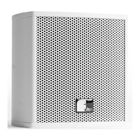
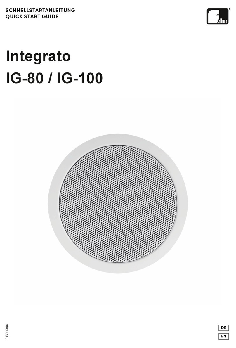
Fohhn INTEGRATO IG-100 User manual

INTEGRATO-SERIES
IG-100
CEILING SPEAKER
USER MANUAL
EN
Please read this user manual through carefully before putting the system into operation and keep it for future reference.

2
Contents
1.1 Important Safety Instructions 4
1.1.1 Explanation of Terms 4
1.1.2 General Safety Instructions 4
1.1.3 Acoustic Safety Information 5
1.1.4 Connections and Cabling 5
1.2 Operating Conditions 6
1.2.1 Information on Abnormal Operation 6
1.3 Storage and Transportation 6
2. The Product 7
2.1 Product Description 7
2.2 Delivery 7
2.3 Unpacking 7
3. Installation 8
3.1 Preparation 9
3.2 Ceiling Cut-Out 9
3.3 Removing the Front Grille 9
3.4 Safety Eyelet 10
3.5 Electronic Connection 10
3.6 Mounting Clamps 11
3.7 Installing the Ceiling Loudspeaker 12
4. Technical Documentation 13
4.1 Technical Data 13
4.2 Technical Drawings 15
4.3 Measurement Diagrams 18

3
5. Service and Repair 22
5.1 Maintenance Measures 22
6. Appendix 23
6.1 Environmental Information 23
6.2 CE Marking and Declaration of Conformity 23
6.3 Trademarks 23
6.4 Disclaimer and Copyright 23
6.5 Contact Address 24

4
1. Introduction and General Instructions
Congratulations on the purchase of your INTEGRATO IG-100 ceiling loudspeaker. Specially developed as an
unobtrusive system for installation in ceilings and walls, the speaker has been kept very compact in response to
demand.
1.1 Important Safety Instructions
Please read the following safety instructions in their entirety before putting this device into operation. Keep these
instructions near the device at all times. Reading the user manual does not replace the need for awareness of and
compliance with currently applicable national safety regulations and standards, or the observance of safe on-site
working methods.
All information and technical specifications published here are based on data that was available at the time of
publication. We expressly reserve the right to make any changes.
1.1.1 Explanation of Terms
Danger
This signal word indicates a hazard with a high risk level, which, if not avoided, could result in death or serious
injury.
Warning
This signal word indicates a hazard with a medium risk level, which, if not avoided, could result in death or serious
injury.
Caution
This signal word indicates a hazard with a lower risk level which, if not avoided, could result in minor or moderate
injury.
1.1.2 General Safety Instructions
Danger:
To avoid danger to life or limb, please ensure that all personnel involved in installing, operating or dismantling the
system have read and understood the contents of this manual.
The information presented here, however, should be regarded as accompanying advice and this does not affect
the ultimate responsibility of the user to ensure safe on-site operation of a FOHHN system.
Warning:
To prevent injury caused by a fallen system,
this device must be securely installed in accordance with the assembly instructions and current
safety guidelines. Only use the specially designed FOHHN mounting accessories or components,
which are explicitly specified in the assembly instructions.
this device must be regularly inspected for any signs of wear or loosening of the load-bearing
connections.
it is necessary to ensure that the mounting points on a building or structure have sufficient load-
bearing capacity and are structurally viable.
all components of a hung (i.e. “flown”), ceiling- or wall-mounted device must be visually inspected
before installation. Any part showing signs of deformity, cracks, rust, fractured welds or other
signs of wear must not be used under any circumstances.

5
the load limit of any component that will be used for system suspension (including shackles,
chains and hoists) must not be exceeded. In order to comply with local safety regulations, these
load limits may, in certain circumstances due to underlying safety factors (operating ratios), need
to be recalculated and, if necessary, reduced.
All components required for the mounting of a FOHHN system have been designed and
constructed in accordance and compliance with the following regulations that are applicable in
Germany: BGV-C1, BGI 810-3, DIN EN 1993-1-1, DIN EN 1999-1-1 und DIN 18032-2
The safety factor (operating ratio) is therefore equal to or better than 10:1. If the system is to be
used in countries that have stricter requirements, the permissible load capacity must be reduced
accordingly.
To avoid injuries, the device must be stored, installed and operated well away from children.
To avoid injuries, this device must be taken out of operation, marked appropriately and protected against
accidental use if it
shows visible signs of damage
appears to contain loose parts
no longer works correctly
has been subjected to unfavourable conditions (e.g. moisture) for a prolonged period
has been subjected to poor transportation conditions (e.g. with unsuitable packaging or damp /
humidity).
If necessary, please contact your FOHHN dealer and the transportation company immediately.
1.1.3 Acoustic Safety Information
FOHHN systems are capable of generating very high sound pressure levels, which can cause irreparable damage
to hearing.
Warning:
To avoid potential hearing impairment, never stand in close proximity (1 metre or less) to a device while it is in
operation.
To prevent both hearing impairment and damage to the device, avoid the following while the device is in
operation:
acoustic feedback
high powered, permanently distorted signals
impulse noises, which can occur when a device is switched on or off, connected or disconnected
from the system.
1.1.4 Connections and Cabling
Please note the following when wiring up your system:
Check that your cable is working faultlessly and only use cables with a sufficient cross section.
Only use cabling- and connector materials that meet professional standards.
Lay and secure the cabling so that it cannot be damaged by tools, or through being trapped by
the device or by a fixing bracket.
Protect any laid cables from mechanical damage, or unnecessary traction.
Avoid excessive tightening of the screws on connection terminals!
The wiring up of loudspeakers should only be carried out by suitably qualified personnel!
6
1.2 Operating Conditions
Please note the following when operating your system:
The permitted ambient temperature of the device during operation ranges from 0 °C to +40 °C.
The device is intended for use in a dry environment with normal levels of dust and humidity in the
air.
If condensation has built up on the device, or on its rear panel during transportation or storage,
let the device acclimatise for ca. 2 hours before using it.
Never expose the device to any aggressive chemical fluids or vapours.
Never expose the device to strong vibration.
1.2.1 Information on Abnormal Operation
The device should be immediately inspected by a FOHHN AUDIO AG approved service partner if
a foreign body or liquid has got into the interior of the device,
the device has been exposed to rain,
the device is not working normally i.e. it is showing marked differences in performance,
the device is damaged (e.g. after a fall).
1.3 Storage and Transportation
Please note the following:
The device should only be transported in its original packaging.
Store the device in a dry environment with a constant ambient temperature in order to avoid
condensation.
The permitted ambient temperature range for storing the device is -10 °C to +70 °C.
Due to fluctuations in temperature during transportation and storage, condensation may start to
build up on the surface of the device. Before operating the device, examine its surface for any
signs of moisture. If this is the case, allow the unpacked device to acclimatise for two hours in the
environmental temperature before using it.

7
2. The Product
2.1 Product Description
The INTEGRATO IG-100 is a compact ceiling speaker with 2-way coaxial design: The loudspeaker is equipped
with a 4″ woofer –with a 0.75″ high frequency driver placed in front – and a crossover with high frequency driver
protection. The system also offers exceptionally even beam dispersion (100° conical).
The IG-100 has a flame-resistant metal enclosure, with a maximum mounting depth of 100 mm, and a flat
protection grille –this grille is magnetically attached and can easily be removed. On the side of the enclosure is a
safety eyelet.
The ceiling speaker is also fitted with an integrated 100-Volt transformer and a 5-stage selector switch. This
enables low-ohm control (16 ohms) and three settings for 100 V operation (30/15/7.5 W) to be selected. During
installation or calibration, the system can be completely switched off if necessary.
2.2 Delivery
Every product is examined in accordance with the highest quality and safety standards prior to despatch.
Please check your product carefully for any signs of transport damage and, in the event of any damage having
occurred, inform your dealer and the transportation company immediately. Please also check that the packaging
contains all the components belonging to the device.
Your IG-100 system is delivered with the following:
1 × IG-100 loudspeaker system
1 × cut-out template
1 × frame painting template
1 × quick start guide
If you have not received all of the above, please contact your FOHHN dealer.
2.3 Unpacking
When unpacking the system, we recommend the following procedure:
Open the packaging and take out the product.
Examine the product for any visible signs of transport damage. If the product has been damaged,
inform the transportation company immediately. A claim for transport damage can only be made
by the recipient (that is to say, you). Keep the packaging for examination by the transportation
company.
As a general rule, always retain the packaging. Despatch the product in appropriate outer
packaging.

8
3. Installation
The IG-100’s exceptionally flat design makes it suitable for a range of installation situations:
in suspended ceilings with at least 100 mm installation depth
in concrete structures –in concrete ceilings with the aid of installation housing: To build the
IG-100 into a concrete ceiling, we recommend the HaloX® 250 System from Kaiser Elektro
(www.kaiser-elektro.de) with the following components:
oHousing: HaloX® 250 –Kaiser article no.: 1283-00
oFront section: HaloX® 250 Universal Front Part –Kaiser article no.: 1283-10
Extension rings are not required as the installation depth of the IG-100 is less than the HaloX®
system’s required 110 mm.

9
3.1 Preparation
If your IG-100 ceiling loudspeaker is no longer the colour you desire, you have the possibility to simply re-paint
any visible parts yourself, such as the front grille and mounting ring. This is relatively straightforward.
a) Remove the front grille (see Chapter 3.3) and paint this separately.
b) Detach the supplied frame painting template from its cardboard surround and place it centrally on the
baffle. This protects the drivers in your IG-100 against any spray.
c) Place at least three small magnetic elements (e.g. washers or nuts) on the template over the IG-100’s
magnets. This will prevent the template from moving.
d) Now you can paint the mounting ring.
Please take note of the relevant safety- and user instructions relating to the paint used!
3.2 Ceiling Cut-Out
Use the template supplied with the product to create the appropriate ceiling cut-out (176 mm in diameter).
Proceed as follows:
a) Detach the round disk from the cut-out template
b) Either use the template’s inner circle to create the installation cut-out –use a pen to mark up the intended
position. Or, use the detached round disk for marking up the cut-out.
TIP: You can facilitate the positioning by applying double-sided sticky tape to the relevant template
section. This will secure it in the required position.
c) Cut the opening in the ceiling according to the template marking then remove the template.
Alternatively, you can make the ceiling cut-out using a circle cutter.
3.3 Removing the Front Grille
The IG-100’s front grille is magnetically attached to the loudspeaker enclosure. To remove the grille, proceed as
follows:
a) Between the front grille and loudspeaker enclosure is a paper strip whose ends can be seen at both
sides.
b) Pull on both ends of the paper strip to lever the grille away from its fixing (see following image).

10
3.4 Safety Eyelet
On the side of the enclosure, to the right of the cable outlet, is an eyelet for securing the loudspeaker in the ceiling
using a safety cable.
TIP: Before actually installing the speaker, we recommend fitting a safety cable and securing the loudspeaker via
the eyelet. This way, the loudspeaker is already hanging in preparation for mounting and the secure connection of
its cabling to the ceiling and therefore cannot accidentally fall to the floor.
3.5 Electronic Connection
For electronically connecting the IG-100, there is a cable outlet on the side of the enclosure with a 2-pin twin wire.
The ends of the single strand wires are pre-fitted with a flexible 3-pin quick-mount WAGO terminal for connecting
the product as follows:
In the above diagram, the red cable represents the positive pole and the black the negative.

11
3.6 Mounting Clamps
Thanks to its three mounting clamps, the IG-100 can be easily, quickly and safely installed. To ensure secure
mounting, the ceiling thickness should not exceed 37 mm! Depending on the ceiling thickness, it is intended that
the mounting clamps be used in one of two positions:
Mounting clamps in their factory positioning for Mounting clamps rotated for ceiling
ceiling thicknesses of 0 mm to 18.5 mm thicknesses of 18.5 to 37 mm
To rotate the mounting clamps for ceiling thicknesses of > 18.5 mm, proceed as follows:
a) Undo the three fixing screws on the inside of the loudspeaker (see following image).
b) Rotate the mounting clamps
c) Screw the mounting clamps back on again.

12
3.7 Installing the Ceiling Loudspeaker
Install the IG-100 as follows:
a) With the front grille removed, slide the loudspeaker - which is secured via its rear eyelet - into the
specially created ceiling cut out.
b) Tighten the three fixing screws with a cross-head screwdriver. The three mounting clamps will fold out
and pull the IG-100 into the ceiling.
c) Using the selector switch, choose your desired setting. Use a slotted screwdriver for this.
The selector switch offers the following settings:
100 V –100 % –30 W
100 V –50 % –15 W
100 V –25 % –7.5 W
OFF (switch off e.g. during installation or calibration)
LOW IMPEDANCE (for low-ohm control –16 ohms)
d) Replace the front grille.
IMPORTANT: To remove the front grille again –without the paper strips –you will just need a pointed item such
as a screwdriver (see following image).

13
4. Technical Documentation
4.1 Technical Data
Electroacoustic features
Acoustic design ceiling loudspeaker, 2-way coaxial
Components 1 x 4″weather resistant cone / 0.75″tweeter with
self-resetting HF protection
Power rating (16 ohms, nominal) [1] 50 W
Power rating (16 ohms, program) [2] 100 W
Power rating (Peak) [3] 200 W
Sensitivity [4] 86 dB
Maximum SPL (16 ohms) [3] 109 dB
Frequency range [5] 85 Hz –20 kHz
Nominal dispersion [6] 100° conical
Nominal impedance 6 Ohm, switchable to 100 V –30/15/7.5 W
General Features
Enclosure steel fire dome, powder-coated
Protection grille steel grille, powder-coated
Mounting points 3 x rotating mounting clamp, 1 x steel safety latch
Connections tool-free quick connectors with loop-through option
Integrated 100 V transformer switchable 30/15/7.5 W –OFF –16 ohms
Standard colours white (RAL 9016)
Dimensions (D x H) 202 Ø x 100 mm
Dimension of baffle Ø 202 mm
Installation depth 99 mm

14
Ceiling cut-out diameter Ø 176 mm
Weight [7] 1.8 kg
Optional features
Optional colours all RAL colours
[1] according to IEC-60268-5 long term
[2] according to IEC-60268-5 short term
[3] Peak, 20 ms with bandpass filtered pick noise signal according to IEC 60268- 2, at one octave above the lower
limit of the frequency range
[4] 2.83 V at 8 ohms (2 V at 4 ohms, 4 V at 16 ohms) at a distance of 1 meter under anechoic halfspace
conditions
[5] -10 dB under anechoic halfspace conditions
[6] nominal dispersion at -6 dB
[7] net weight without optional equipment

15
4.2 Technical Drawings

16

17

18
4.3 Measurement Diagrams
Polar response, horizontal

19
Conical coverage, horizontal
Directivity

20
Frequency response
Impedance
Other manuals for INTEGRATO IG-100
1
This manual suits for next models
1
Table of contents
Other Fohhn Speakers manuals

Fohhn
Fohhn EasyPort User manual

Fohhn
Fohhn LINEA LEN–20 User manual

Fohhn
Fohhn INTEGRATO IG-100 User manual

Fohhn
Fohhn Focus Modular User manual

Fohhn
Fohhn Linea Focus DLI-130 User manual

Fohhn
Fohhn Linea FocusDLI-230 User manual

Fohhn
Fohhn AIREA LX-10 ASX User manual

Fohhn
Fohhn FP-22 modular User manual

Fohhn
Fohhn EasyPort FP-Media User manual

Fohhn
Fohhn AT-05 User manual