Fohhn LINEA LC Series User manual

DESIGNLAUTSPRECHER FÜR HÖCHSTE
SPRACHVERSTÄNDLICHKEIT.
LINEA LC
LC20 / LC60 / LC100 / LC150 / LC220
BEDIENUNGSANLEITUNG | USER MANUAL
Bitte lesen Sie vor Inbetriebnahme des Gerätes die Bedienungsanleitung sorgfältig durch und bewahren Sie sie auf.
Please read this manual carefully before operating the equipment and keep it for the future reference.
LINEA LC

CONTENT | ENGLISH
1. IMPORTANT SAFETY INFORMATION 15
1.1 Connections and cabling 15
2. INTRODUCTION 16
2.1 Intended readers of this manual 16
2.2 Scope of supply 16
2.3 Unpacking the product 16
3. SETUP AND OPERATION 17
3.1 Installation and mounting 17
3.2 Wiring 21
3.3 Operating conditions 22
3.4 Transportation and storage 22
3.5 Maintenance 22
3.6 Servicing and repair 22
4. TECHNICAL DATA 23
5. ACCESSORIES 24
6. EG CONFORMITY CE MARKING 25
7. WEEE DIRECTIVES DISPOSAL 25
14

MARKINGS AND DEFINITIONS
DANGER
This term is used to denote high-risk hazards which, if not prevented, can
result in death or serious injury.
WARNING
This term is used to denote medium-risk hazards which, if not prevented,
can result in death or serious injury.
CAUTION
This term is used to denote low-risk hazards which, if not prevented, can
result in minor or moderate injury.
DANGER
To avoid risk of injury or death, please make sure that anyone involved in
installing, operating or dismantling the system has read this user manual.
WARNING
To prevent any potential injury caused by the system falling down,
• it must be firmly fixed to building structures according to the
mounting instructions. Please also ensure that these structures
combined with the equipment used for system deployment have
sufficient load-bearing capability and are structurally suitable.
Only use the recommended FOHHN accessories with this product, or
other components that have been explicitly specified in this manual.
• it must be regularly checked for any signs of wear or loosened parts
on load bearing connections.
To minimize the risk of fire or electric shock,
• the system should not be opened: It does not contain any parts to
be maintained by the user. For maintenance requirements, please
consult a qualified technician.
• items that have a naked flame (such as candles) should not be placed
near the system.
To avoid injury, this product must be taken out of operation, appropri-
ately marked and secured against unauthorised use if
• it shows any visible signs of damage.
• there is any indication of loose parts.
• it does not work properly.
• it has been subjected to poor transportation conditions (e.g. with un-
suitable packaging).
1. IMPORTANT SAFETY INFORMATION
Please read the following safety information carefully before using the system. This information should be kept handy for
future reference. Reading this manual does not replace the need for awareness and observation of all current local safety
regulations, legal requirements and compliance with safe working methods at the venue.
The following information and technical specifications have been based on data that was available at the time of publica-
tion. We expressly reserve the right to make changes as necessary.
To avoid injury
• this product must not be stored, installed or operated in reach of
children.
To prevent hearing damage caused by excessive sound pressure levels,
do not
• stand directly in front of a loudspeaker, that is ready for operation,
without wearing ear protection.
• subject yourself to high sound pressure levels over a long time period.
CAUTION
To prevent damage to the product, please avoid the following:
• acoustic feedback
• high powered, permanently distorted signals
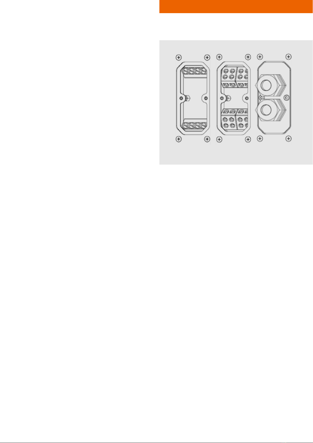
1.1 CONNECTIONS AND CABLING
Cables form the vital links between the different components in an audio
system.
Please make sure that your cables are in perfect working order. Only use
branded cables of an appropriate cross section!
Speaker cables must be laid and secured in a way that they cannot be
harmed by tools or jammed and damaged by the loudspeaker or wall
brackets.
Wiring of loudspeaker must be solely executed by skilled personnel. We
recommend using ferrules for stranded wires.
Avoid excessive torque to the terminal screws!
IMPORTANT SAFETY INFORMATION | ENGLISH 15

2. INTRODUCTION
Congratulations on purchasing a FOHHN®LC loudspeak-
er system. LC loudspeakers are passive, weatherproof line
source systems with aluminium housing, specially designed
for use in fixed installations where the highest demands for
speech intelligibility and visual appearance must be met.
They are equally suited to indoor or outdoor use.
LEN loudspeaker systems feature two-way technology with
integrated passive filters that guarantee an even disper-
sion and the best possible coverage. An integrated FOHHN
SOURCE DIVISION WAVEGUIDE effectively suppresses side
lobes, resulting in improved speech intelligibility for acousti-
cally challenging venues with long reverberation times, such
as railway stations, airports, auditoria and conference halls.
2.1 INTENDED READERS
OF THIS MANUAL
This user manual outlines the operation and potential ap-
plications of the LINEA LC loudspeaker. The information is
aimed at system technicians, users and anyone else involved
in setting up, operating and dismounting the system.
2.2 SCOPE OF SUPPLY
All FOHHN products are developed by qualified engi-
neers. During the build process, current safety regula-
tions are always kept in mind. Each product is thorough-
ly tested before leaving the factory.
Please examine your new product carefully for any signs
of damage that may have occurred during transporta-
tion and, if necessary, inform your dealer and the trans-
port company immediately. Please also check that the
packaging includes all components belonging to the
product.
Your LINEA LC system contains the following components:
1 × LC20 / LC60 / LC100 / LC150 / LC220
1 ×quick start guide
1 ×cover plate
(including 2 x cable glands & dummy plugs)
If anything is missing, please let your FOHHN dealer
know immediately.
2.3 UNPACKING THE PRODUCT
When unpacking the system, we recommend proceeding
as follows.
1. Open the packaging and take out the product.
2. Check the product carefully for any signs of damage
during transportation.
If any is found, please notify the transport com-
pany immediately. Recompense for damage during
transportation can only be claimed by the consign-
ee i.e. you. Please retain all packaging for exami-
nation by the transport company.
3. The packaging should ideally be kept in any case, as
products should never be returned without their original
packaging.
INTRODUCTION | ENGLISH 16

SETUP AND OPERATION | ENGLISH
3. SETUP AND OPERATION
3.1 INSTALLATION AND MOUNTING
Depending on the particular model, LC loudspeakers can
be mounted on building structures using the following wall
brackets (see Chapter 5 “Accessories”):
WAL1, WAL03, WLX100, WLX221
Loudspeaker mounting within buildings should only be car-
ried out by trained personnel.
Please ensure that the wall brackets you have selected are
suitable for use with the product to be installed.
We recommend that you read Chapters 1 and 2 of this user
manual carefully. You must also observe any relevant na-
tional safety requirements.
CONNECTION TO BUILDING STRUCTURES
• Make sure that the building structure to which the loud-
speaker will be connected is statically suitable.
• Surfaces that support brackets must be sufficiently sta-
ble and not be subject to long-term settlement.
• Wall plug and screw connections must be of sufficient
size to cope with the tensile strength required. This will
also depend on the type and inclination of the particu-
lar speaker mounting.
• If you are uncertain about any of the above points, it
is imperative to consult a qualified structural engineer.
CONNECTIONS BETWEEN LOUDSPEAKERS AND
BRACKETS
• All FOHHN brackets include fastening materials for
connecting them to the loudspeaker. If you want to use
other screws, their strength must be at least class 8.8;
this corresponds to a tensile strength of 800 N/mm² and
a 0.2 % proof stress of 640 N/mm².
• Never use screws that are longer than the originals
supplied. This could damage structures inside the loud-
speaker, or cause a short circuit.
• When connecting the following brackets to LC series
loudspeakers, a tightening torque of 10 Nm is required:
WAL1, WAL03, WLX100, WLX221. This applies to
standardised screws without washers: DIN 912/6912,
DIN 931/933, ISO 7380.
SAFETY
• Regardless of any currently applicable legal require-
ments, we strongly recommend securing all systems to
a second separate point. Any M6 thread points on LC
loudspeakers are suitable for this purpose. The two sets
of threads above the connection panel and on the up-
per end of the housing rear wall are specifically intend-
ed for this.
• DIN 580 C15 forged eyelets can be used for anchoring
the system. SEE FIGURE 1.
• To secure the loudspeaker, only suitably sized permit-
ted elements (such as wire ropes, shackles or quick
links) should be used. The maximum falling distance,
before the safety element is engaged, should be as
small as possible and must not exceed 200 mm.
Figure 1
17
• When anchoring the system to the wall, dynamic
strength caused by the falling loudspeaker must also
be considered.

SETUP AND OPERATION | ENGLISH
MOUNTING WITH WAL1 BRACKETS
1. Remove the two oval-head screws from the top and
base of the loudspeaker.
SEE FIGURE 2.
2. Fix both WAL1 brackets to the wall using two screws
and wall plugs in each case. The loudspeaker itself
serves as the best distance gauge.
When mounting the longer LC150 and LC220
loudspeakers models, it makes sense to fix the low-
er bracket first and determine the position of the top
bracket using the actual loudspeaker.
Allow play of ca. 2 mm between the loudspeaker
and the bracket.
3. It is advisable to affix the supplied rubber wash-
ers around the drill holes on the top and bot-
tom surfaces of the speaker. This will prevent
the powder coating from becoming scratched.
SEE FIGURE 3.
4. Slide the loudspeaker between the two brackets.
5. Screw the brackets to the loudspeaker using the sup-
plied M6x25 screws and washers. Do not tighten the
screws at this point.
Apply medium-strength thread lock fluid to both
screws beforehand.
6. Adjust the loudspeaker then firmly tighten both screws
according to the required torque.
Figure 2
Figure 3
18

SETUP AND OPERATION | ENGLISH 19
MOUNTING WITH WLX100 / WLX221 WALL BRACKETS
1. Remove both oval-head screws M6 (D) at the mount-
ing plate and loosen the screws (C, F, G) by about three
turns.Removethemountingplatefromthewallbracket.
SEE FIGURE 4.
2. Remove the fourto six M6 oval-head screws thatare lo-
cated underneath the connector panel. SEE FIGURE 5.
3. Fix the loudspeaker to the WLX100/WLX221 mount-
ing plate. Apply medium-strength thread lock fluid to
all screws. On both brackets, use four of the locking
screws you just removed. Tighten all screws according
to the required torque. SEE FIGURE 6.
4. Fix the WLX100 or WLX221 to the building structure
using two screws and wall plugs. To do this, you will
need to disassemble the mounting bracket from the wall
bracket. During installation, don‘t forget to place the two
tooth-lock washers (A) between the mounting bracket
and the wall bracket. Make sure that the wall brack-
et is mounted with the horizontal slot facing upward.
SEE FIGURE 7.
5. Put the mounting bracket in a roughly vertical position by
turning the adjustment spindle (B) to the right.
6. Place the loudspeaker and its mounting plate on the
wall bracket. Both sides of the mounting plate must be
resting on the screw (C). SEE FIGURE 8.
7. At this point the fixing screws (D) can be fitted and
tightened with a torque of 8-10 Nm. There are two op-
tions here: If the front holes (20) are to be used, this will
result in an adjustment angle of 0-20°; if the rear holes
(30) are used, this will result in an adjustment angle of
10-30°.
8. Set up the required inclination angle by turning the ad-
justment spindle (B) to the left. If you need to reduce
the angle again, turn the spindle back while pushing
the speaker slightly up towards the wall bracket and
thus releasing the spindle.
9. Loosen the clamping screws (E) on the horizontal axis
and turn the loudspeaker to its required position.
10. Once you are happy with the loudspeaker’s angle and
rotation, tighten the clamping screws (E) with a torque
of 20 Nm. Tighten the screws (C, F, G) with a torque of
8 to 10 Nm.
Figure 4
Figure 6
Figure 8
Figure 5
A
E
E
A
C
D
F
G
B
Figure 7

SETUP AND OPERATION | ENGLISH 20
MOUNTING WITH THE WAL03 BRACKET LEN20 ONLY
1. Remove the two M6 oval-head screws that are located
underneath the connector panel. SEE FIGURE 9.
2. Fix the WAL3 to the wall using two screws and wall
plugs. For this, use the part containing the two slotted
holes at right angles.
3. Fix the bracket to the loudspeaker using the WAL3’s
mounting plate. Apply medium strength thread lock
fluid to all screws. Firmly tighten all screws using the
required torque.
4. Tighten the M8 nut (F) just as far as it is still possible to
turn and angle the loudspeaker. Set the required rota-
tion and inclination angles. SEE FIGURE 10.
5. Once you are happy with the above angles, tighten the
M8 nut (F) using a torque of 18 Nm.
Figure 9
Figure 10

SETUP AND OPERATION | ENGLISH
3.2 WIRING
All LC series loudspeakers are passive systems designed
for use with external amplifiers. They have identical ca-
bling connectors and can be supplied with a choice of two
options:
• 2 × 4 plastic terminal blocks are supplied as standard.
These are suitable for wires with a cross section of up
to 4 mm².
• The loudspeakers can also be supplied with 2 × 4 ce-
ramic terminal blocks. These are suitable for wires with
a cross section of up to 2.5 mm².
All cables used must be of an appropriate cross section. We
recommend using ferrules for stranded wires.
A sealing plate is attached to each loudspeaker, along with
two M16 cable glands. Once cabling has been completed,
this can be used to cover the connector panel and provide
tension relief for the cable.
Please be aware of the fact that the specified degree of
protection (in accordance with IEC 60529) is only obtained
by mounting the sealing plate correctly. The cable glands
are suitable for use with cables of between 6 and 10 mm
in diameter.
If only one cable is being used, the other cable gland
should be replaced by the dummy plug that has been sup-
plied with the loudspeaker.
Plastic terminals Ceramic terminals Cable outlet
21

SETUP AND OPERATION | ENGLISH
3.3 OPERATING CONDITIONS
The recommended operating temperature range for this
system is -25 °C to +70 °C. If used in temperatures below
0˚ C, the system should be permanently operated using a
pilot tone in order to prevent the system from freezing and
getting stuck.
Always allow the system to acclimatise before using it.
Do not subject the system to aggressive chemical liquids
or vapours.
Always ensure that heat can be dissipated over the exter-
nal surfaces of the housing.
The system should be well ventilated at all times. To en-
sure sufficient air-flow, it should not be covered with tow-
els. Heat from the sun and strong lighting should also be
avoided.
Do not subject this system to strong vibrations!
3.4 TRANSPORTATION AND STORAGE
This system should only be transported in its original pack-
aging.
Store it in a dry place with an even temperature, so that it
is not affected by condensation.
The recommended temperature range for storing this sys-
tem is -10 °C to +70 °C.
3.5 MAINTENANCE
Clean the system as required using a damp cloth. Do not use
any cleaning products that contain aggressive chemicals.
3.6 SERVICING AND REPAIR
Servicing and/or repairs should only be carried out by
qualified personnel who have been trained by FOHHN.
Do not carry our any servicing or repair on a system other
than stated above.
To find a FOHHN Service centre in your area, please con-
tact us at the address on the back page of this manual.
Keep the packaging that has been supplied with this sys-
tem so that, in the event of any damage, it can be returned
in its original packaging. This will reduce the risk of any
further damage occurring during transportation.
22

TECHNICAL DATA | ENGLISH
4. TECHNICAL DATA
23
Model LC-20 LC-60 LC-100 LC-150 LC-220
Number of 4" drivers with treated cones 2 6 8 12 18
2-way design No Yes Yes Yes Yes
Power rating (nominal) [1] W 60 180240360440
Power rating (program) [2] W 120360480720880
power rating (peak) [3] W 24072096014401760
Sensitivity [4] dBSPL 93 97 98 100101
Maximum SPL dBSPL117125127131133
Frequency range [5] Hz
Nominal dispersion (hxv) [6.2] Deg 130 x 60 130 x 25 130 x 15 130 x 14 130 x 14
Nominal impedance Ohms 16 12 8 4 4
Housing
Mounting points 4xM6 8xM6 8xM6 8xM6 10xM6
Protection class acc. toIEC529/EN60529
Weight [7] kg 2,5 6 8 11,5 16
Width mm 130130130130130
Depth mm 120120120120120
Height mm 23064099014602200
Standard colours
Optional features
Custom colours
Weather protection
Terminal
CAAD Simulation data
Optional accessories
Wallbracket WAL-1 x x x x x
Wallbracket WAL-03 x
Wallbracket WLX-100 x x x
Wallbracket WLX-221 x
[6.2] horizontal x vertical at -6 dB, averaged 1-4 kHz
[7] net weight without optional equipment
120 - 12000
All measurements normalized to freefield full-space conditions
[2] according to IEC-60268-5 short term
egnarycneuqerfehtfotimilrewolehtevobaevatcoenota2-86206CEIotgnidroccalangisesionknipderetlifssapdnabhtiwsm02,kaeP]3[
[4] 2,83 V at 8 ohms (2 V at 4 ohms, 3,46 V at 12 ohms, 4 V at 16 ohms) normalized to a distance of 1 meter
[5] -10 dB under anechoic halfspace-conditions
IP54
[1] according to IEC-60268-5 long term
Acoustic design weatherproof passive line source speaker system, closed, passive 2-way CD crossover and filter,
suppression of side lobes by Source Division Waveguides (SDW)
Mechanical features
Electroacoustical features
all RAL classic colours
EASE, Ulysses, CLF
black (RAL 9005) or white (RAL 9016)
ceramic terminals capable of receiving up to 2,5mm2
weatherproof without further protection as standard
Front design ball impact resistant steel grille, galvanized and powder coated in enclosure colour, backed by
acousticallytransparent foam
terminal connectors capable of receiving up to 4mm2, two per pin, terminal cover with dual cable gland
for up to 10mm cable diameter
Terminal
weatherproof aluminium housing, powder coated, steel bracings

5. ACCESSORIES
ACCESSORIES | ENGLISH
WAL1
LC loudspeaker with wall bracket
WLX100
WAL03
WLX221
24

6. EG CONFORMITY CE MARKING
This loudspeaker complies with the currently applicable conditions of EMC law and as such, carries the CE
marking.
The relevant Declarations of Conformity are available on request from FOHHN AUDIO AG
CERTIFICATES | ENGLISH 25
7. WEEE DIRECTIVES DISPOSAL
Electrical and electronic components must not be disposed of in standard household waste. For this
reason we include the dustbin symbol shown here on our products and in manuals.
Please consult your dealer or distributor regarding product disposal in your particular country.

FOHHN®AUDIO AG
Hohes Gestade 3-8
72622 Nürtingen
Germany
Tel. +49 7022 93323-0
Fax +49 7022 93324-0
www.fohhn.com
DB0092X Stand 10.04.2018
FOHHN®im Social Web
This manual suits for next models
5
Table of contents
Other Fohhn Speakers manuals

Fohhn
Fohhn LINEA LEN–20 User manual

Fohhn
Fohhn AIREA LX-10 ASX User manual

Fohhn
Fohhn EasyPort FP-Media User manual

Fohhn
Fohhn AT-05 User manual

Fohhn
Fohhn Focus Modular User manual

Fohhn
Fohhn INTEGRATO IG-100 User manual

Fohhn
Fohhn EasyPort User manual

Fohhn
Fohhn EASY PORT FP2pro User manual

Fohhn
Fohhn Linea FocusDLI-230 User manual

Fohhn
Fohhn Linea LX-10 User manual