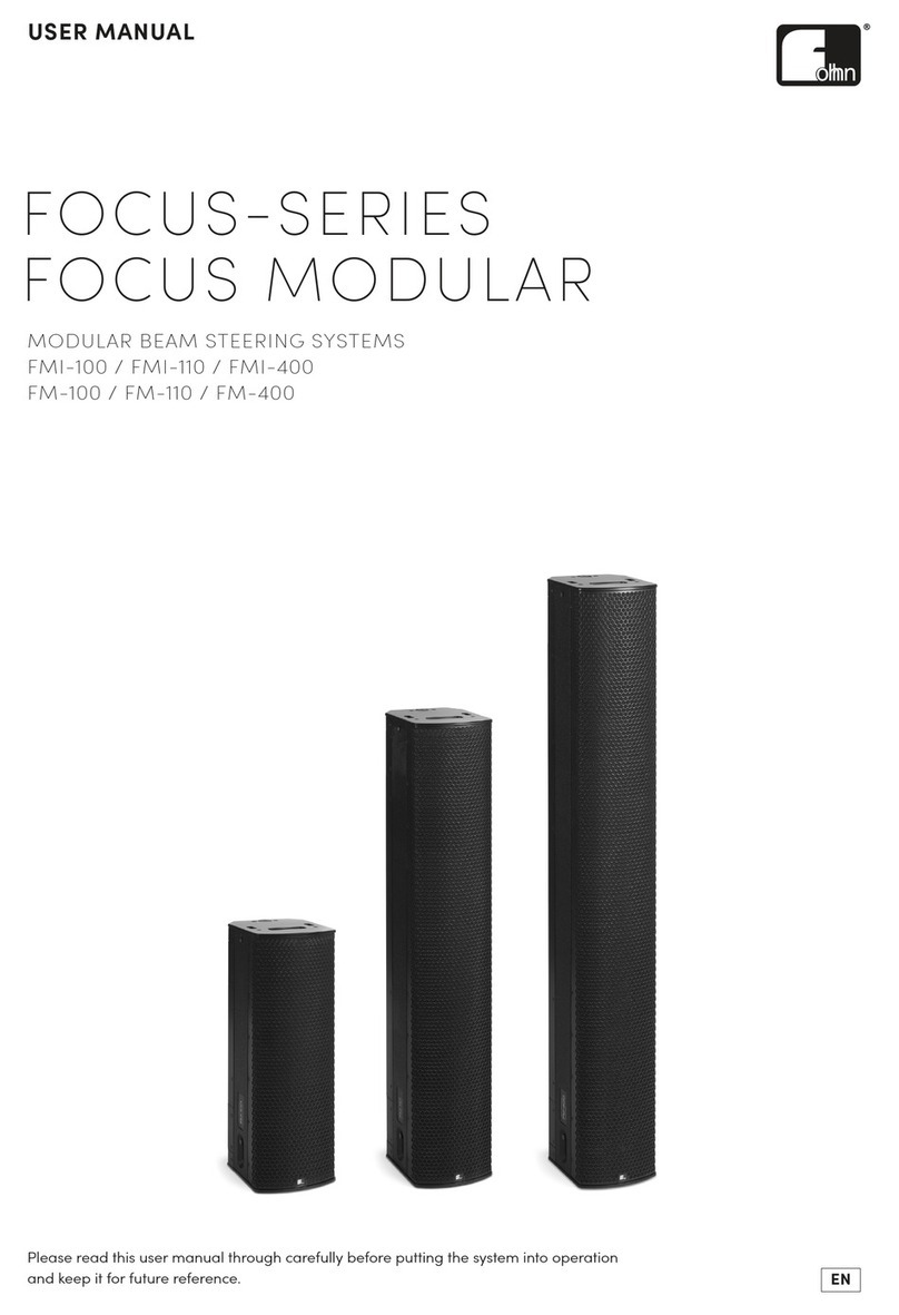
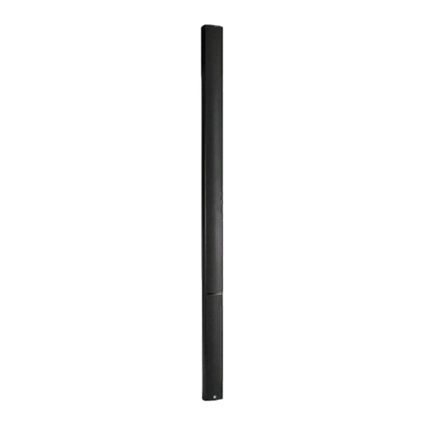
Fohhn Focus Modular User manual

1
Version 1.0 / Oct. 2021
Copyright by Fohhn Audio AG 2021; all rights reserved.
Please read this user manual through carefully before putting the system into operation and keep
it for future reference.

2
Contents
1. Introduction and General Information............................................................................................... 5
1.1 Safety Instructions...................................................................................................................... 5
1.1.1 Explanation of Terms.......................................................................................................... 5
1.1.2 General Safety Instructions ................................................................................................ 6
1.1.3 Electrical Safety Information .............................................................................................. 7
1.1.4 Acoustic Safety Information ............................................................................................... 8
1.2 Connections and Wiring ............................................................................................................. 8
1.3 Operating Conditions.................................................................................................................. 8
1.4 Storage and Transportation........................................................................................................ 9
2. The Product...................................................................................................................................... 10
2.1 Product Description.................................................................................................................. 10
2.2 Delivery and Unpacking............................................................................................................ 11
2.3 Product Identification............................................................................................................... 11
2.4 Accessories ............................................................................................................................... 12
3. Mechanical Setup and Rigging ......................................................................................................... 13
3.1 Wall mount installation............................................................................................................ 13
3.2 Rigging a Focus Modular System.............................................................................................. 13
3.2.1 Rigging System of a Focus Modular Module .................................................................... 13
3.2.2 Flying adapter VFM-1, number of arrayable modules...................................................... 14
3.2.3 Cardan Clamp CC-300 ....................................................................................................... 16
3.2.4 Safety chains..................................................................................................................... 17
3.2.5 Flying from the hook of a crane or chain hoist................................................................. 18
3.2.6 Flying from traverses or bars............................................................................................ 23
3.2.7 Rain covers for outdoor use.............................................................................................. 24
4. Wiring and Software Setup .............................................................................................................. 27
4.1 Wiring ....................................................................................................................................... 27
4.1.1 Input panel........................................................................................................................ 27
4.1.2 Output panel..................................................................................................................... 29
4.2 General configurations............................................................................................................. 29
4.3 Hardware and Software Requirements.................................................................................... 31
4.4 Downloading and Installing Fohhn Audio Soft ......................................................................... 31
4.5 Fohhn Net ID Allocation ........................................................................................................... 32
4.6 Identifying Connected Systems................................................................................................ 33
4.7 Renaming Devices / Channels .................................................................................................. 34
4.8 Graphically Arranging the Loudspeaker System....................................................................... 34
4.9 Combining Modules to a Speaker Stack................................................................................... 35

3
4.10 Loading Loudspeaker Presets................................................................................................... 36
4.11 Further Options ........................................................................................................................ 36
4.11.1 Auto Power Save............................................................................................................... 36
4.11.2 Password Lock................................................................................................................... 37
4.11.3 Tilt Sensor ......................................................................................................................... 37
4.12 Adjusting level relations within an array.................................................................................. 38
5. Control via Fohhn Audio Soft ........................................................................................................... 39
5.1 Beam Steering –the functional principle................................................................................. 39
5.1.1 Side Lobe Free Technology ............................................................................................... 39
5.1.2 Two Beam Technology (Two Beam Mode)....................................................................... 40
5.1.3 Acoustic Centre................................................................................................................. 42
5.2 Setup in the Beam Steering View............................................................................................. 42
5.3 Adjustment of DSP Functions................................................................................................... 44
5.4 Saving Projects.......................................................................................................................... 45
6. Application Examples....................................................................................................................... 46
6.1 Smaller venues with a single audience level............................................................................ 46
6.2 Larger venue with a single audience level................................................................................ 47
6.3 Large venues with two audience levels.................................................................................... 49
6.4 Large venues with three or four audience levels ..................................................................... 50
7. Technical Documentation ................................................................................................................ 52
7.1 Technical Specifications............................................................................................................ 52
7.1.1 DFM-100 ........................................................................................................................... 52
7.1.2 DFM-110 ........................................................................................................................... 54
7.1.3 DFM-400 ........................................................................................................................... 56
7.2 Technical Drawings................................................................................................................... 58
7.2.1 DFM-100 ........................................................................................................................... 58
7.2.2 DFM-110 ........................................................................................................................... 60
7.2.3 DFM-400 ........................................................................................................................... 62
7.3 Pin Assignments and Cable Lengths......................................................................................... 64
8. Troubleshooting............................................................................................................................... 65
9. Service and Repair............................................................................................................................ 66
9.1 Maintenance Measures............................................................................................................ 66
10.Glossary............................................................................................................................................ 67
11.Appendix .......................................................................................................................................... 68
11.1 Environmental Information...................................................................................................... 68
11.2 CE Marking and Declaration of Conformity.............................................................................. 68
11.3 Trademarks............................................................................................................................... 68
11.4 Protection Classes and Protection Types ................................................................................. 68
11.5 Disclaimer and Copyright ......................................................................................................... 69

4
11.5.1 Disclaimer ......................................................................................................................... 69
11.5.2 Copyright........................................................................................................................... 69
11.6 Contact Address........................................................................................................................ 69
5
1. Introduction and General Information
Congratulations on the purchase of your Fohhn Focus Modular system. The DFM modules are the new
generation of the renowned FM modules, which are now fully digitized and provide further developed
Fohhn DSP and digital signal connections. Acoustically redesigned and equipped with even more
powerful drivers, DFM delivers excellent, audiophile sound and best speech intelligibility. A high-
quality and high-performance solution for larger conference rooms, theatres and even open-air
concerts. And all of this with an enclosure that is just about 22 cm wide and can be flown straight and
integrated seamlessly thanks to beam steering. The Fohhn Beam Steering Technology allows users to
adjust the system’s vertical beam dispersion characteristics in real time, enabling optimum sound
coverage –even in the most acoustically challenging venues.
All the functions of a Focus Modular system can be controlled using a single piece of software, Fohhn
Audio Soft.
To benefit from all the advantages of your Focus Modular system and to guarantee smooth
operation, please read the following user instructions carefully before putting the system into
operation and keep this manual for future reference!
1.1 Safety Instructions
Please read the following safety instructions in their entirety before putting your Focus Modular
system into operation. Always keep these instructions near the device. Reading the user manual does
not replace the need for awareness of and compliance with currently applicable national safety
regulations and standards, or the observance of safe on-site working methods.
All information and technical specifications published here are based on data that was available at the
time of publication. We expressly reserve the right to make any changes.
1.1.1 Explanation of Terms
Danger!
This signal word indicates a hazard with a high risk level, which, if not avoided, could result in death
or serious injury.
Warning!
This signal word indicates a hazard with a medium risk level, which, if not avoided, could result in
death or serious injury.
Caution!
This signal word indicates a hazard with a lower risk level, which, if not avoided, could result in minor
or moderate injury.

6
1.1.2 General Safety Instructions
Danger!
To avoid danger to life or limb, please ensure that all personnel involved in installing or
deconstructing such a system have read and understood the contents of this manual.
All personnel should be aware of local regulations concerning workplace safety. It is strongly
recommended to wear suitable helmets and safety footwear during the rigging procedure.
The information presented here should, however, be regarded as accompanying advice and it does
not affect the ultimate responsibility of the user to ensure safe on-site operation of a Focus Modular
system.
Warning!
To prevent injury caused by a collapsing system,
-this device must be securely mounted in accordance with the rigging instructions and current
safety guidelines. Only use the specially designed Fohhn mounting accessories or
components, which are explicitly specified in the rigging instructions.
-this device must be regularly inspected for any signs of wear or loosening of the rigging
connections.
-it is necessary to ensure that the mounting points on a building, scaffolding or truss structure
have sufficient load-bearing capacity and are structurally viable.
-all components of a hung (i.e. “flown”) device must be visually inspected before installation.
Any component showing missing parts, deformations, cracks, corrosion, fractured welds or
other signs of wear must not be used under any circumstances.
-the load limit of any component that will be used for system suspension (including shackles,
chains and hoists) must not be exceeded. In order to comply with local safety regulations,
these load limits may, in certain circumstances due to underlying safety factors (operating
ratios), need to be recalculated and, if necessary, reduced.
-it is strongly recommended that a flown (loudspeaker) system should be landed and
dismounted if local wind intensity is equal or greater than 6 Bft (Beaufort Scale).
All components required for the mounting or suspension of a Focus Modular system have been
designed and constructed in accordance and compliance with the following regulations that are
applicable in Germany: DGUV V17 (formerly BGV-C1), DGUV I215-313 (formerly BGI 810-3), DIN EN
1993-1-1 and DIN EN 1999-1-1.
The operating ratio against non-elastic deformation (yield strength) is equal to or better than 5:1, the
operating ratio against fracture (tensile strength) is equal to or better than 7:1 for an array with a gross
weight of 300 kg. If the system is to be used in countries that have stricter requirements, the
permissible load capacity must be reduced accordingly.
Warning!
To prevent injury through accidents, the stability of the entire Focus Modular system (e.g. during
assembly, in a vertical stack or when using a pole-mounted flange) must be guaranteed. Make sure
that the system cannot topple over (e.g. as the result of a sloping surface or wind) and that it is
protected against being hit from people or vehicles, for example.

7
Caution!
To avoid injury,
-the device must be stored, installed and operated well away from children.
-no one must climb on either flown or stacked loudspeaker systems.
-the device must be taken out of operation, marked appropriately and protected against
accidental use if it
-shows visible signs of damage.
-appears to contain loose parts.
-is not working correctly.
-has been subjected to poor transportation conditions (e.g. with unsuitable packaging).
If necessary, please contact your Fohhn dealer and the transportation company immediately.
Contact details can be found in the appendix to this user manual.
1.1.3 Electrical Safety Information
Focus Modular systems are Protection Class 1 appliances. They are built and certified in accordance
with the VDE safety measures for electronic devices and, safety-wise, leave our factory in perfect
condition. The devices comply with all currently applicable EMC directives: Confirmed by the attached
CE marking.
The relevant guidelines can be found in the appendix to this user manual.
Warning!
To minimize the risk of electric shock
-the mains plug grounding pin must never be separated and under no circumstances should
the plug be taped up.
-the device must only be connected to a professionally tested shockproof socket.
-the amplifier housing and loudspeaker enclosure must never be opened. It does not contain
any components that can be repaired by the user. In the case of a defect, please consult
qualified service personnel and/or the dealer from whom you purchased the system.
Please also ensure that the local mains supply voltage matches the power supply voltage specified
on the device.
To minimize the risk of an electric shock or fire,
-the device must not be subjected to moisture / wet conditions for a long period of time.
-containers filled with liquid (e.g. beverage containers) must not be placed on the device.
-ventilation slots must not be covered with objects (e.g. protective rain covers).
-the device must not be subjected to excessive heat, sunshine, fire or similar.
-no open sources of flame (e.g. pyrotechnics) must be placed on the device.
Caution!
To avoid damaging the device, do not leave the power cable plugged in if the device is not going to
be used for a while. (Remove the plug from the mains socket to completely disconnect the device.)

8
1.1.4 Acoustic Safety Information
Focus Modular loudspeaker systems are capable of generating very high sound pressure levels, which
can cause irreparable damage to hearing.
Warning!
To avoid potential hearing impairment, never stand in close proximity (5 metre or less) to a device
while it is in operation.
To prevent both hearing impairment and damage to the device, avoid the following while the device
is in operation:
-acoustic feedback
-high powered, permanently distorted signals
-impulse noises, which may occur when some other device in the signal chain is switched on
or off, connected or disconnected from the system, e.g. a mixing desk, audio matrix or
controller.
1.2 Connections and Wiring
Warning!
Please note the following when wiring up your system:
-Make sure that all cables are working faultlessly.
-Only use cables with a sufficient cross section.
-Only use cabling- and connector materials that meet professional standards.
-Only use properly shielded cables and plugs for audio and data connections.
-Only use power cables with a fully intact grounding pin
-Lay and secure the cabling in a way that it cannot be damaged by tools, machinery, the
loudspeakers itself or its flying accessories.
-Lay the cabling in such a way that it cannot be tripped over.
-Protect any laid cables from unnecessary traction.
-Note the respective pin assignment of audio and data cabling.
-Never use any signal or power cables for mounting, hoisting or securing a system.
Wiring of loudspeakers should only be carried out by suitably qualified personnel.
More information can be found in section 4.1Fehler! Verweisquelle konnte nicht gefunden werden.
of this user manual.
1.3 Operating Conditions
Caution!
Please note the following when operating your Focus Modular system:
-The permitted ambient temperature of the device during operation ranges from 0 °C to
+40 °C. A short period of use outside this temperature range is possible, but not advisable.
-The device is intended for use in a dry environment with normal levels of dust and humidity
in the air.
-Never expose the device to any aggressive chemical fluids or vapours.

9
-Always make sure that heat can be dissipated via the rear surface of the device enclosure.
-Always make sure that the device is well ventilated. To ensure adequate cooling, the device
must not be covered with towels or cloths. Avoid letting the enclosure become hot through
exposure to sunlight or strong spotlights.
-To guarantee sufficient cooling for the device, the following minimum gaps must be
maintained: left/right side >5 cm, back >10 cm, top >10 cm.
-Never expose the device to strong vibration.
Information on abnormal Operation:
If the permissible operating temperature is too high (over 75 °C), the device will shut down. As soon
as the temperature returns to within the normal operating range, the device will automatically power
up again.
The temperature of the Focus Modular loudspeaker system will be displayed in Fohhn Audio Soft.
Shutdown is getting more likely if the product is exposed to direct sunlight or very high environmental
temperatures. Reliable operation is only guaranteed in compliance with the permissible ambient
temperature range.
Warning!
The device should be immediately inspected by a Fohhn Audio AG approved service partner if
-the mains power socket is damaged,
-a foreign body or liquid has got into the interior of the device,
-the device is not working normally i.e. it is showing marked differences in performance,
-the device is damaged (e.g. after a fall).
1.4 Storage and Transportation
Please note the following:
-The device should only be transported in its dedicated transport case.
-Store the device in a dry environment with a constant ambient temperature to avoid
condensation.
-The permitted ambient temperature range for storing the device is -10 °C to +70 °C.
-Due to fluctuations in temperature during transportation and storage, condensation may start
to build up on the surface of the device. Before operating the device, examine its surface for
any signs of moisture. If this is the case, allow the unpacked device to acclimatise for two hours
in the environmental temperature before using it.

10
2. The Product
2.1 Product Description
Fohhn Focus Modular loudspeaker systems, which form part of the Focus-Series, are active, modular
loudspeaker systems designed both for touring applications and fixed installation use.
The special feature of these systems is their integrated Beam Steering Technology: Using dedicated
control software, Fohhn Audio Soft, the systems’ vertical beam dispersion characteristics can be
intuitively controlled in real time and thereby optimally adjusted to suit the particular application.
Conventional mechanical curving, i.e. the physical adjustment of the line curvature is no longer
necessary, though in some cases mechanical inclination of a Focus Modular array may improve the
acoustical result.
The current version of the required Fohhn Audio Soft software can be downloaded free of charge from
www.fohhn.com.
The following modules are available:
-DFM-100: high frequency module
-DFM-110: high frequency module
-DFM-400: low-mid frequency module
The high frequency modules are equipped with 8 or 16 1” compression drivers respectively, and a
preceding Fohhn waveguide system. Each high frequency driver is separately powered by a Class-D
amplifier channel. The high frequency modules have a frequency range of 1,7 kHz to 20 kHz and can
only be used in combination with one or more low-mid modules.
The low-mid module is equipped with 32 long excursion cone speakers. The chassis are driven in pairs
by 16 Class-D amplifier channels. The frequency range is 55 Hz to 1,7 kHz.
DFM-400 modules are linkable to longer stacks in an array with other DFM-400.

11
A brief overview is given in the table below:
The modules can be acoustically and mechanically combined as required to suit the particular
application and space situation. Long reach and optimal sound results can be achieved even in
acoustically difficult situations.
2.2 Delivery and Unpacking
Every Focus Modular module is examined in accordance with the highest quality and safety standards
prior to despatch.
Please check your product carefully for any signs of transport damage and, in the event of any damage
having occurred, inform your dealer and the transportation company immediately. Please also check
that the packaging contains all the components belonging to the device.
Your Focus Modular module is delivered with the following:
-1x Focus Modular module DFM-100, DFM-110 or DFM-400
-1x powerCON mains cable
-1x powerCON mains link cable
-1x etherCON link cable
-1x safety instructions
When unpacking the system, we recommend the following procedure:
1. Examine the packed product for any signs of transport damage.
2. Remove all packing material from the product.
3. Examine the product for any signs of transport damage. Don´t forget the bottom surface.
4. If the product has been damaged, inform the transportation company immediately. Any claim
for transport damage must be made by the you, the consignee. Keep the packing material for
examination by the transportation company.
2.3 Product Identification
The Focus Modular module’s type designation can be found below the upper connection panel at the
rear side of the speaker.
Module
DFM-100
DFM-110
DFM-400
Components
8x 1” driver
16x 1” driver
32x 4” chassis
Amplifier channel
8x 120 W, Class-D
8x 120 W, Class-D
16x 120 W, Class-D
Frequency range
1,7 - 20 kHz
1,7 –20 kHz
55 Hz - 1,7 kHz

12
2.4 Accessories
Setting up a Focus Modular module requires a Windows PC (Windows 7 or higher) with Fohhn Audio
Soft installed and a Fohhn network adapter or –if connected via Fohhn Airea –an AIREA breakout box.
Product ID
Article number
Description
NA-11
6115-00000
Fohhn Net USB Adapter
NA-4
6122-00000
Fohhn Net Ethernet Adapter
ABX-2
1716-00000
Analogue NF and Fohhn Net to Airea converter
ABX-5
1719-00000
Dante to Airea converter and Fohhn Net Ethernet
Adapter
AM-4.4
1714-xxxxx
Airea Master
The following accessories are available:
Product ID
Article number
Description
WFM-100
8441-B0000
Wall-mounting bracket for DFM-100, black
WFM-110
8442-B0000
Wall-mounting bracket for DFM-110, black
WFM-400
8443-B0000
Wall-mounting bracket for DFM-400, black
VFM-1
8444-B0000
Flying adapter, black, including:
- 2 x shackles with 1000 kg WLL
- 1 x shackle with 2000 kg WLL
CC-300
8320-B0000
Cardan Clamp, black, with rotation brake, for use with
VFM-1, 300 kg SWL (Safe Working Load)
RC-FM-100
8147-00000
Rain cover for FM-100 / FMI-100, sound permeable,
extendable via zip fastener
RC-FM-110
8148-00000
Rain cover for FM-110 / FMI-110, sound permeable,
extendable via zip fastener
RC-FM-400
8149-00000
Rain cover for FM-400 / FMI-400, sound permeable,
extendable via zip fastener
RC-FM-LID1
8150-00000
Lid for FM-/FMI rain cover, closed
RC-FM-LID2
8151-00000
Lid for FM-/FMI rain cover, open, for use with VFM-1
FM-CASE
8156-00000
System flight case for any two modules

13
3. Mechanical Setup and Rigging
3.1 Wall mount installation
On the back of each Focus Modular module, two M8 threaded inserts can be found at both the top
and bottom. These are solely intended for attaching dedicated wall brackets.
3.2 Rigging a Focus Modular System
3.2.1 Rigging System of a Focus Modular Module
Each Focus Modular module has two aluminium supporting tubes integrated into its enclosure. These
are located behind the right and left side panels respectively and can be accessed via slots in the
aluminium covers that form the top and bottom ends of the enclosure. The two tubes carry the entire
weight of the system –both must therefore always be used during installation.
At the lower end of each supporting tube is a steel latch. It can be extended, enabling the Focus
Modular module to be joined to another module. A knurled-head screw acts as a handle when moving
the latch and keeps the latch locked within the enclosure during transportation, or when the system is
not in use. The knurled-head screw may be tightened as soon as the latch is connected to a rigging pin
to avoid rattling noise at high SPL of the system.
A visible yellow tag on the latch indicates, that the latch is not connected to the respective slot in the
lower module correctly.

14
To connect the Focus Modular modules to one another, or to flying adapters, two ball lock pins are
used. During transportation, these ball lock pins can be securely housed in two pilot holes on the
connector panel.
Danger!
Always make sure, no yellow tag is visible at the two latches and all ball lock pins are inserted
correctly before hoisting the system.
3.2.2 Flying adapter VFM-1, number of arrayable modules
To fly an array of Focus Modular modules, the flying adapter VFM-1 is required. Its load capacity is
300 kg, which is the limit for any possible array combination including cabling and accessories.
The total number of 6 modules may safely be suspended.
Warning!
Using any other form of suspension is expressly forbidden.
b
a
c

15
Focus Modular is a modular Beam Steering system. In its main mode of application, it is usually flown
or suspended in a vertical, linear format. However, in some cases it can be advantageous –for acoustic
or optical reasons –to carry out a mechanical inclination.
The VFM-1 has three suspension points for different purposes.
1. Vertically straight alignment: Use (a) as main rigging point to set up an array that hangs
vertically straight without any degree of tilt. In this instance, the supplied 2t shackle in
accordance with DIN 13889 must be used.
Attach elements to (b) which enable horizontal alignment of the Focus Modular system. If
cables are used for this purpose, the tensile direction should, ideally, be approximately
horizontal to prevent the modules from tilting.
2. Vertically tilted alignment: Use (b) as main rigging point to set up an array with a slight forward
tilt without the need for a second rigging point. In this instance, the supplied 2t shackle in
accordance with DIN 13889 must be used.
The inclination angle depends on the numbers of modules in the array and their type and is
given in the table below for serval module combinations.
Top
Middle
Bottom
Incl. angle
DFM-100
14,5°
DFM-110
8°
DFM-400
7,5°
DFM-400
DFM-100
4°
DFM-400
DFM-110
3,5°
DFM-400
DFM-400
DFM-100
2,5°
DFM-400
DFM-400
DFM-110
2,5°
DFM-100
DFM-400
5°
DFM-110
DFM-400
4°
DFM-100
DFM-400
DFM-400
3°
DFM-110
DFM-400
DFM-400
2,5°
DFM-400
DFM-400
4°

16
3. Safety chains: The two permanently attached 1t shackles at (c) are only to be used for safety
cables or chains. Never use just one of these two suspension points.
If (b) is chosen to be the main rigging point, the safety chain and a 2t shackle can be attached
to (a), provided that any potential outward swing of the module is also prevented in the event
of a failure.
Please refer to section 3.2.4.
Danger!
Under no circumstances must a Focus Modular stack be tilted or inclined sideways –either during
use, assembly or dismantling. This could cause structural overload and damage to the internal
and/or external flying hardware. Viewed from the front, every Focus Modular system must hang
vertically.
The use of a CC-300 Cardan Clamp guarantees vertical suspension, regardless of the installation
situation, and is therefore mandatory in this particular case.
3.2.3 Cardan Clamp CC-300
The Cardan Clamp CC-300 can be used to mount a Focus Modular system to a traverse or bar, while
the array remains in its centre of gravity without tilting sideways. Other advantages are an ease in
rigging and in the horizontal alignment of the system.
a
b
c

17
The CC-300 consists of three components:
1. Half Coupler (a): The Half Coupler used here is a fixed system component, which should not
be removed or substituted for other components that may appear identical in construction.
The coupler’s clamping screw should always be secured to a bar via use of lock nuts.
2. Gimbal suspension (b): This suspension ensures that, under all operating conditions, no load
bending can affect the connection between the traverse/bar and the Focus Modular system
and that, even in the case of vertically slanting traverses, the system can hang unhindered in
its central position of gravity.
3. Y-branch with rotation brake (c): Adapter to be attached to a VFM-1.
3.2.4 Safety chains
Despite all checks and worst-case scenario considerations, any component could fail during the flow
of force between load and suspension point. This could either be a shackle or a motorized chain, or
even the suspension points of the rig or building itself.
Warning!
To guarantee the best possible degree of safety for staff, performers and public, we strongly
recommend the use of safety chains as a secondary safety component at all times –even when using
steel reinforced multi-layer slings and lifting belts like STEELFLEX and even if it´s not required by local
safety regulations. This is most important since Focus Modular has been designed as a single-point-
suspension system.
When selecting safety chains, their workload limit (WLL) has to be greater than the entire weight of
the system (loudspeaker modules, flying adapter, cables, motors etc.) plus a safety margin
complying with local regulations. We recommend using safety chains with a WLL of minimum 2t and
a safety factor of 6. They should also be attached to a secure point that is structurally separate from
the actual system suspension point at the truss, scaffold or building.
Never use just one of the safety chain suspension points of the VFM-1.
Once the Focus Modular system has reached its final working height, all safety chains have to be
pulled tight and attached to the safety suspension point as tight as possible. Any failure of a
suspension element should only lead to a minimal drop in height, the maximum drop distance should
be not more than 10 cm to keep the dynamic forces as low as possible.
It is also necessary to ensure that the system cannot or only marginally rotate or swing when
dropping into the safety chains. The best method of securement is via a chain bridle, which can be
attached to the two shackles of the safety skids.
With flown systems that involve a CC-300 Cardan Clamp, it is important to ensure that rotation and
alignment of the system remains possible.

18
Main and secondary safety
chains installed correctly
Safety chains are too loose
Safety chain suspension
points must not be used as
main rigging points
3.2.5 Flying from the hook of a crane or chain hoist
Due to its slimline construction, a Focus Modular system cannot be horizontally pre-assembled on the
ground and hoisted as a complete unit. Assembly requires that each individual module is first hoisted
and then (by slightly lowering the rig/motor) placed on top of the next lowest, upright module.
Proceed as follows:
1. Start by connecting each Focus Modular module to Fohhn Audio Soft and check its Fohhn Net
ID. To avoid any confusion during assembly, mark each module, e.g. with a sticker on its front
grille that shows the Fohhn Net ID. This can be removed before the system is flown. It may be
helpful to put together a brief overview of all integrated Fohhn Net devices, along with their
respective ID numbers.
2. Connect the top module to the VFM-1 by inserting the VFM-1’s latches into the slots on the
top of the Focus Modular module. Only use the ball lock pins of the Focus Modular module
located in their pilot holes in the connector panel. Therefore, the VFM-1 must be slightly
raised.
Danger!
Make sure that both pins are fully inserted and that their collars are fastened to the metal
of the supporting tube.

19
3. Attach the VFM-1 to the hook of the motor or crane by using the supplied 2t shackle and the
suspension point described in section 3.2.2.
4. Fasten the safety bridle to both 1t shackles. If using separate cables or chains for both points,
make sure that these are exactly of the same length and that they are attached to the same
point. Please refer to section 3.2.4.
5. Wire power cable, Airea data or Fohhn Net and digital audio data. Relief the cables to avoid
them from dragging on the VFM-1.

20
6. Raise the currently suspended module to a height that enables you to position the next module
directly underneath it.
7. Carefully lower the suspended module until it sits on top of the standing module. Stop the
motor as soon as the chain loses its tension. Then align both modules horizontally with one
another.
Warning!
Never put your hands in between the two modules.
8. Loosen the knurled-head screws on the upper module’s latches and slide them into the lower
module’s supporting tubes. A visible yellow tag on the latch indicates that the latch is not fully
inserted, and adjustment is needed. Keep the knurled-head screws loosened for the moment.
This manual suits for next models
3
Table of contents
Other Fohhn Speakers manuals

Fohhn
Fohhn Linea FocusDLI-230 User manual

Fohhn
Fohhn FP-22 modular User manual

Fohhn
Fohhn EASY PORT FP2pro User manual

Fohhn
Fohhn EasyPort User manual

Fohhn
Fohhn LINEA LEN–20 User manual

Fohhn
Fohhn EasyPort FP-Media User manual

Fohhn
Fohhn Linea Focus DLI-130 User manual

Fohhn
Fohhn AIREA LX-10 ASX User manual

Fohhn
Fohhn AT-05 User manual

Fohhn
Fohhn INTEGRATO IG-100 User manual