FOLLO FUTURA STABILIS WALKER User manual
FOLLO STABILIS WALKER
17/04/18
Side 2
Rev: 21

We congratulate you on choosing a Follo Stabilis product. This instruction information
makes i t able for you to take full advantage of the product from the first day in use.
Please read these instructions carefully before taking the product into use.
Contents: Check list, unpacking/iInstallation, safety information, how to use,
maintenance instructions, technical specifications and spare parts list
Flat packed Walkers are controlled according to our procedure in ISO 9001 system.
ORDER NO.:
COLOUR:
SERIAL NO.:
ELECTRIC
GAS 200N 250N
FUNCTION TEST: Arm rest/surface: No damages
Bottom frame: Wheels, Screws, plastic parts Battery function
Top frame: Surface, srews, plastic parts Labels: Serial number
Glide tube: Welding, surface, Silicon grease ENCLOSED:
Gas: Adjusting handle Instructions
Screws
ASSEMBLED (date/sign.):
END CONTROLLED (date/sign.):
PACKING CONTROL: (date/sign.):
FOLLO FUTURA AS -POSTBOKS 112 -1430 ÅS -NORWAY
www.follo-futura.no
17/04/18
Side 3
Rev: 21

Unpacking / Installation:
1. Make sure that the product has not been damaged (hurt) in
transport.
2. Fit the walker according to assembly instructions.
3. Assemble all the accessories that have been ordered.
4. Test all the various functions and setting options.
Security Information:
1. If there is any damage or defects in the walker should not be
used until these are rectified.
2. The Walker is designed for indoor use.
3. When adjusting height and depression, make sure that nothing
is pinched between the frame parts.
4. The Walker should never be charged with more than the
approved static use weight.
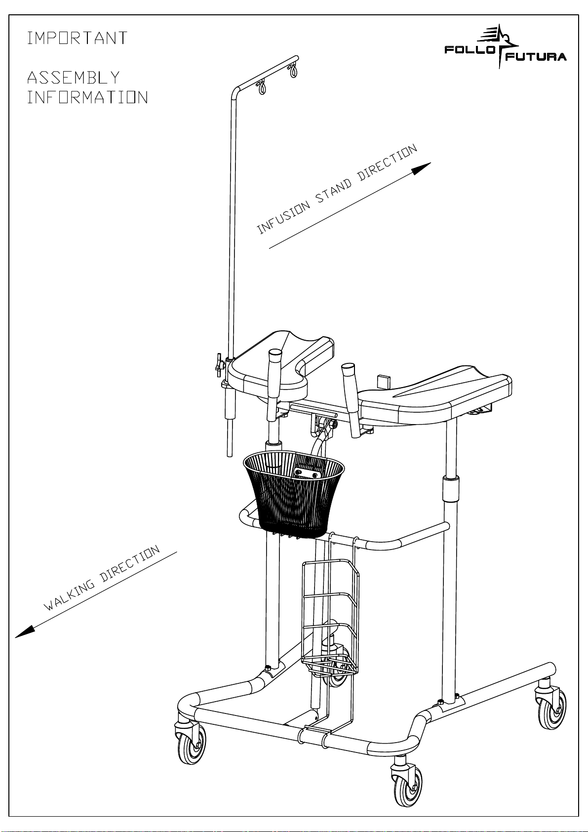
5. Infusion stand has to be mounted parallel to the walker. (See
illustration on page 1).
6. The electric walker should not be used with the charger
attached to the wall outlet.
Guarantee:
The product must not be modified or be used with other items
than original parts. The manufacturer responsibility for CE
marking is invalidated if any form of modification is carried out.
The product carries a 1-year guarantee on cushions.
Not against shipping damage, cuts or using alcohol-
based cleaners.
The product carries a 1-year guarantee on gas shock
absorbers.
The product carries a 2-year guarantee on electrical
parts.
The product carries a 5-year manufacture guarantee on
mechanical constructions.
This product has been assembled, controlled and approved in
accordance with the company’s quality assurance system.
Instructions for use:
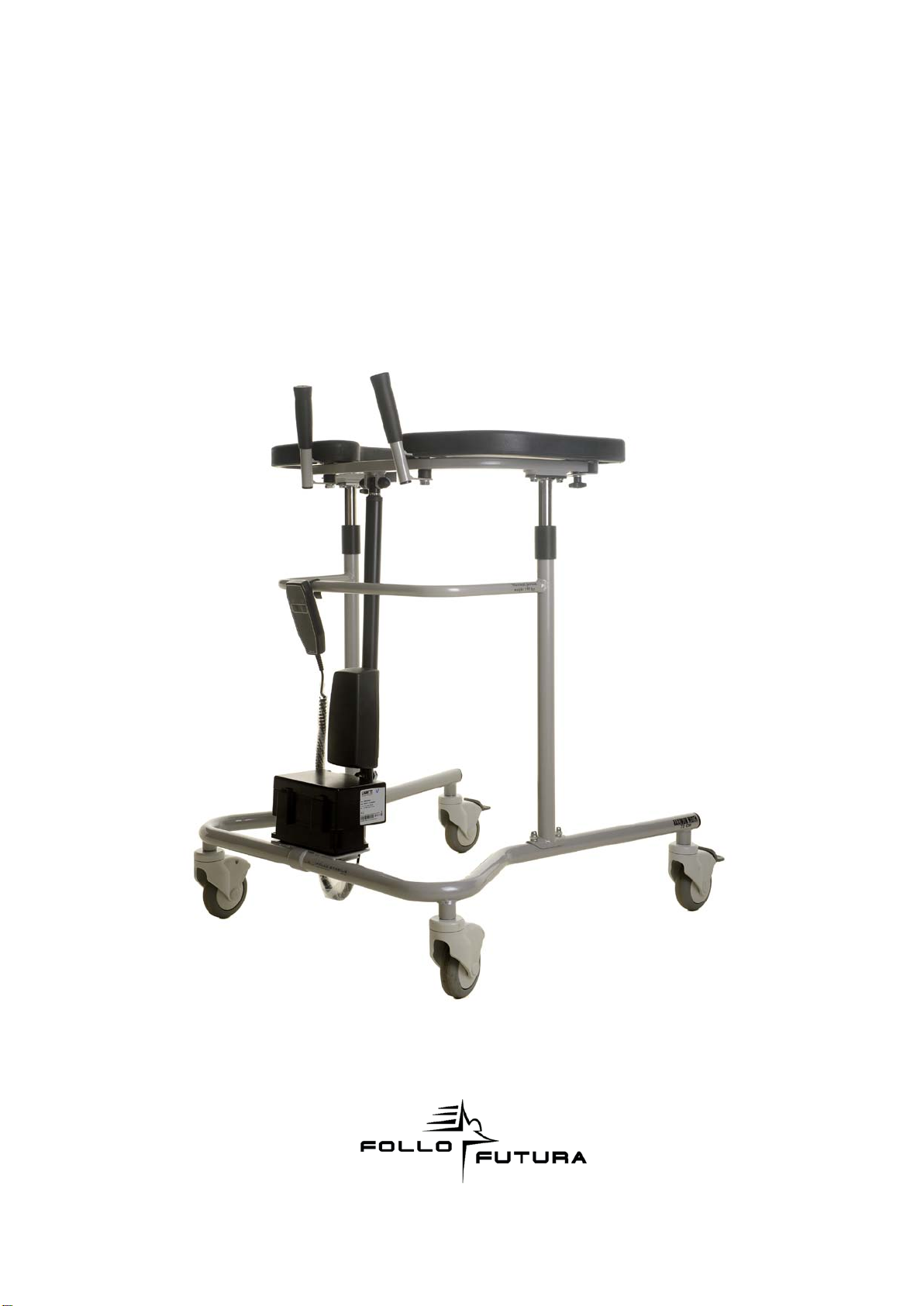
Height Control of walker with gas spring: The handle on the front
of the top frame activates the gas spring. Squeeze the handle to
the top frame to adjust the walker up or down. To lower the
walker, squeeze the handle and load the armrest with body
weight, then drop the handle at the desired level.
Height Control of walker with electric motor: The height of the
armrests is adjusted with the controller to the desired height. The
product is also delivered with maneuvering feature integrated into
the handles.
Height adjustment of the manual version:
Height is adjusted by loosening the clamp
handle on the front tube. Adjust the top
section to the correct height and tighten
the clamp handle. Make sure the clamp
handle is securely tightened.
Cushions adjustment:
Loosen the handles. Adjust the
cushions to the desired position,
tighten the handles. (Make sure they
are tightened). Please note: support
handles follow the armrest setting and
facilitates appropriate support and
use.
Wheels locking: The rear wheels have locks. To unlock the
brakes press down the "locking" with the foot. To release the
brakes tilt "locking" up again with the toe.
Maintenance / inspection:
Control at regular intervals (for example every third months):
1. That all screws are tight and all functions are working properly.
2. That there is no damage or wear and tear on the walker and
the walker is stable.
3. That the braking effect on the brakes is adequate.
4. That the telescopic tubes are lubricated regularly (with a thin
layer of, for example, Vaseline or silicone).
The cushions are made of polyurethane foam, and can easily be
wiped off with most detergents.
Attention! Alcohol-based products discolor the cushions. The
motor, the control box and the controller should be wiped off with
a slightly moist cloth.
Reconditioning:
• Reconditioning of the product must be performed by
professionals.
• Before cleaning / disinfection, remove the cushions. Control Box
is attached with Velcro must be easily removed from the base
frame, a hand control follows with. Engine disassembles easily by
removing two M10 bolts and nuts, see the groundbreaking
design.
• After cleaning / disinfecting, wipe product carefully so that
moisture dislodges. It is very important that all cavities are
inspected for moisture.
• When the product is dry, Telescopic tube must be lubricated
with silicone spray and top frame is moved up and down a few
times so that the parts slide easily. After mounting of cushions,
check the sideway adjust alignment and if the felt is in place.
• Replace worn parts and ordered by the supplier, see the
exploded drawing and part list.
• All worn / damaged Information - and warning labels must be
replaced. These ordered from the supplier.
• The product assembles in accordance with groundbreaking
design.
Recycling:
The motor, the control box and the hand control are disposed of
as electronic waste. The cushions are disposed of as combustible
waste, while the stand etc. are sorted as metal.
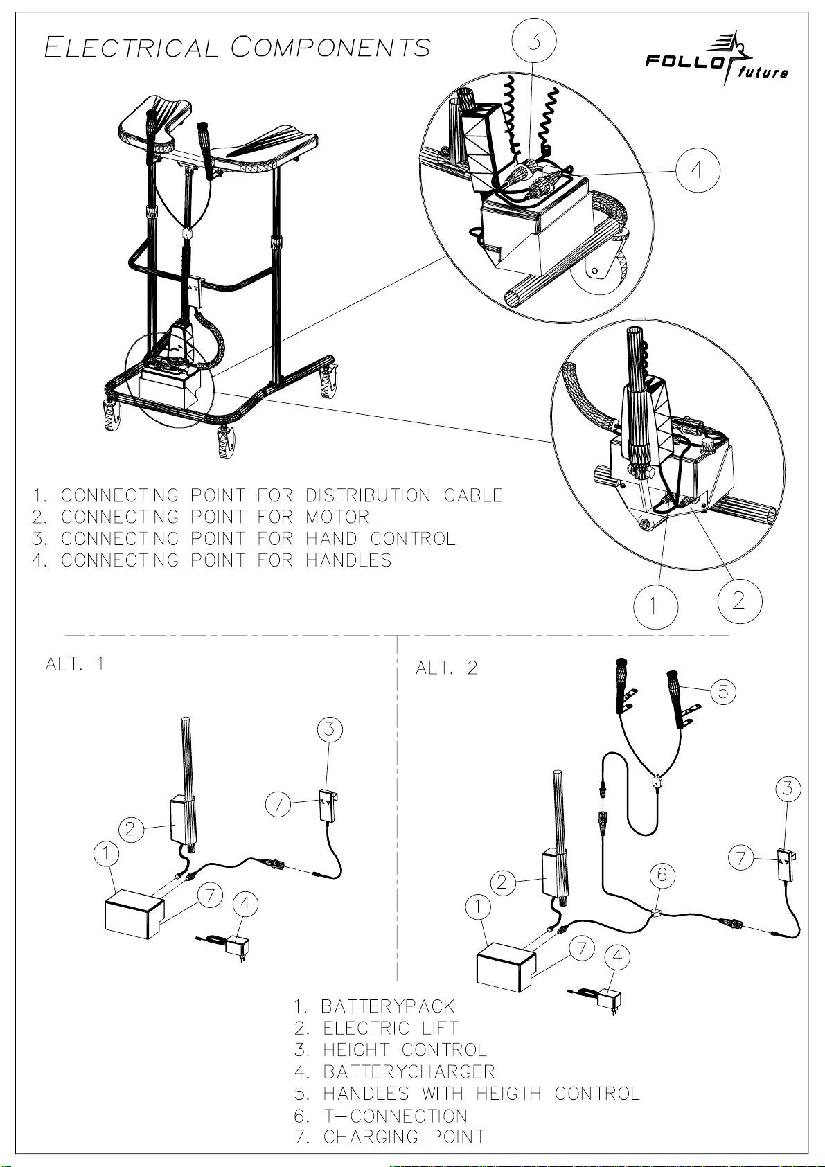
Charge Routines:
When charging the Follo Stabilis Walker, the charger should
always first be connected to the walker before plugging into the
wall outlet. Disconnection is performed in the reverse order.
The batteries are usually fully charged at delivery, but they should
nevertheless be set to charge overnight before Follo Stabilis
Walker is applied. The charging should always be done in room
temperature. It should always be charged when the warning
sound appears (a beep sound). The battery should never be
completely emptied. The battery will not be destroyed by too
much charge.
NOTE: The walker should NOT be used with the charging
device (A) connected.
The charging takes place via the battery pack (B) or via the
controller (C). The charging unit (A) is inserted into a hole on the
left side products. The unit is charged via a common wall outlet.
17/04/18
Side 4
Rev: 21
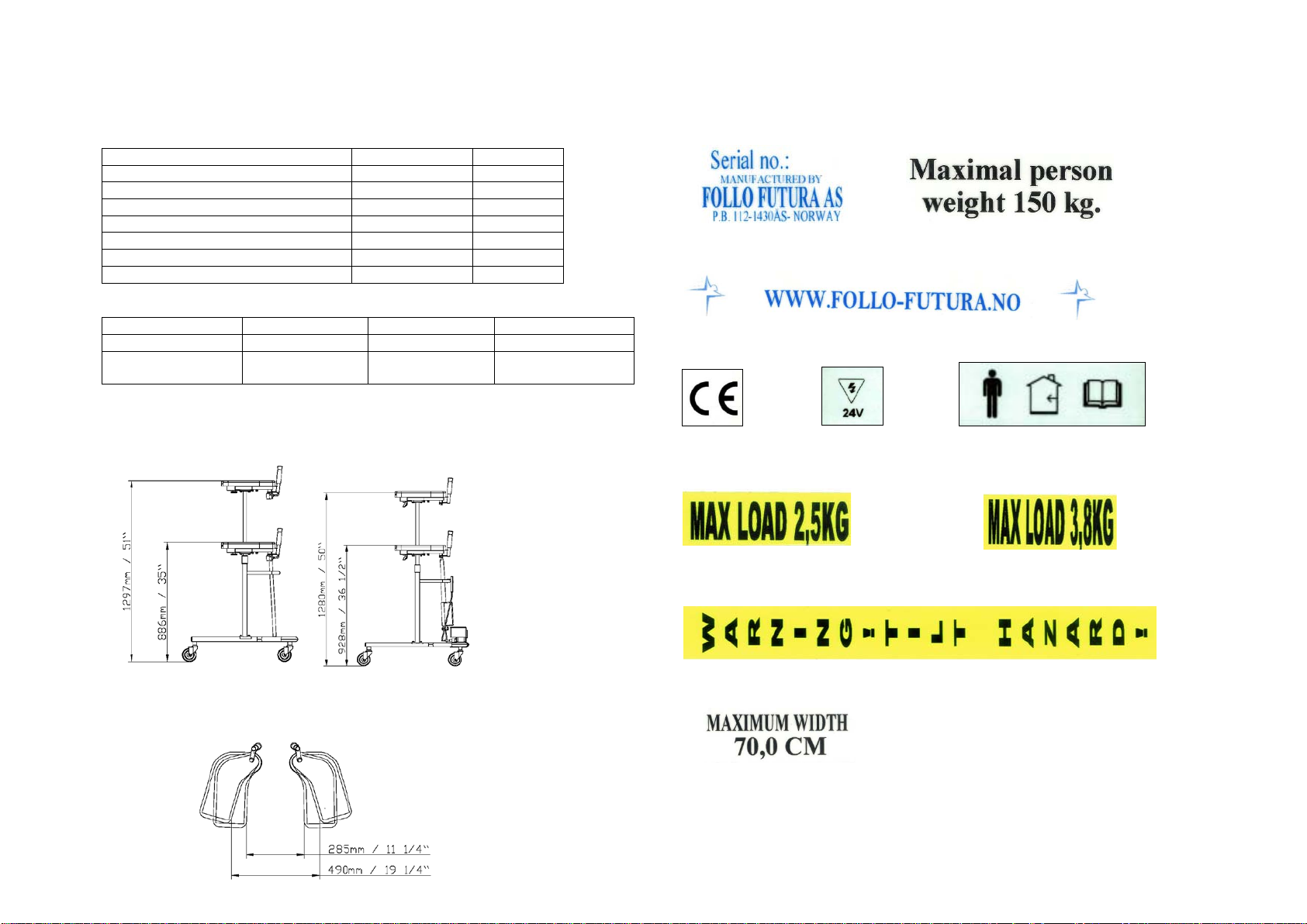
Technical specifications
Cm
Inch
Height min / max manual
88 / 128
34½ / 50½
Height min / max gas
88,6 / 129,7
35 / 51
Height min / max el.
92,8 / 128
36 ½ / 50
Width
81
31 ¾
Length
79,5
31 ¼
Width lower frame
70
27 ½
Minimum turn with lower frame
100
39 ¼
Manual
Gass
Elektrisk
Weight
16,2 kg / 35,6 lbs
14,7 kg / 32,6 lbs
20,6 kg / 45,7 lbs
Maximum user
weight
150 kg/ 333,3 lbs
150 kg / 333,3
lbs
150 kg / 333,3 lbs
Height gas: Height El:
Width between cushions:
Labelling
1. Manufacturer’s name and address, serial number and max. load
2. Web address.
3. CE label 4. Location of charging point 5. For indoor use and consult
operator’s manual
6. Max load on the basket. 7. Max load on the holder for oxygen bottles
8. Warning tilt hazard with use of infusion support, read instruction manual.
9. Max width on lower frame.
17/04/18
Side 5
Rev: 21

17/04/18
Side 6
Rev: 21
17/04/18
Side 7
Rev: 21
17/04/18
Side 8
Rev: 21

17/04/18
Side 9
Rev: 21

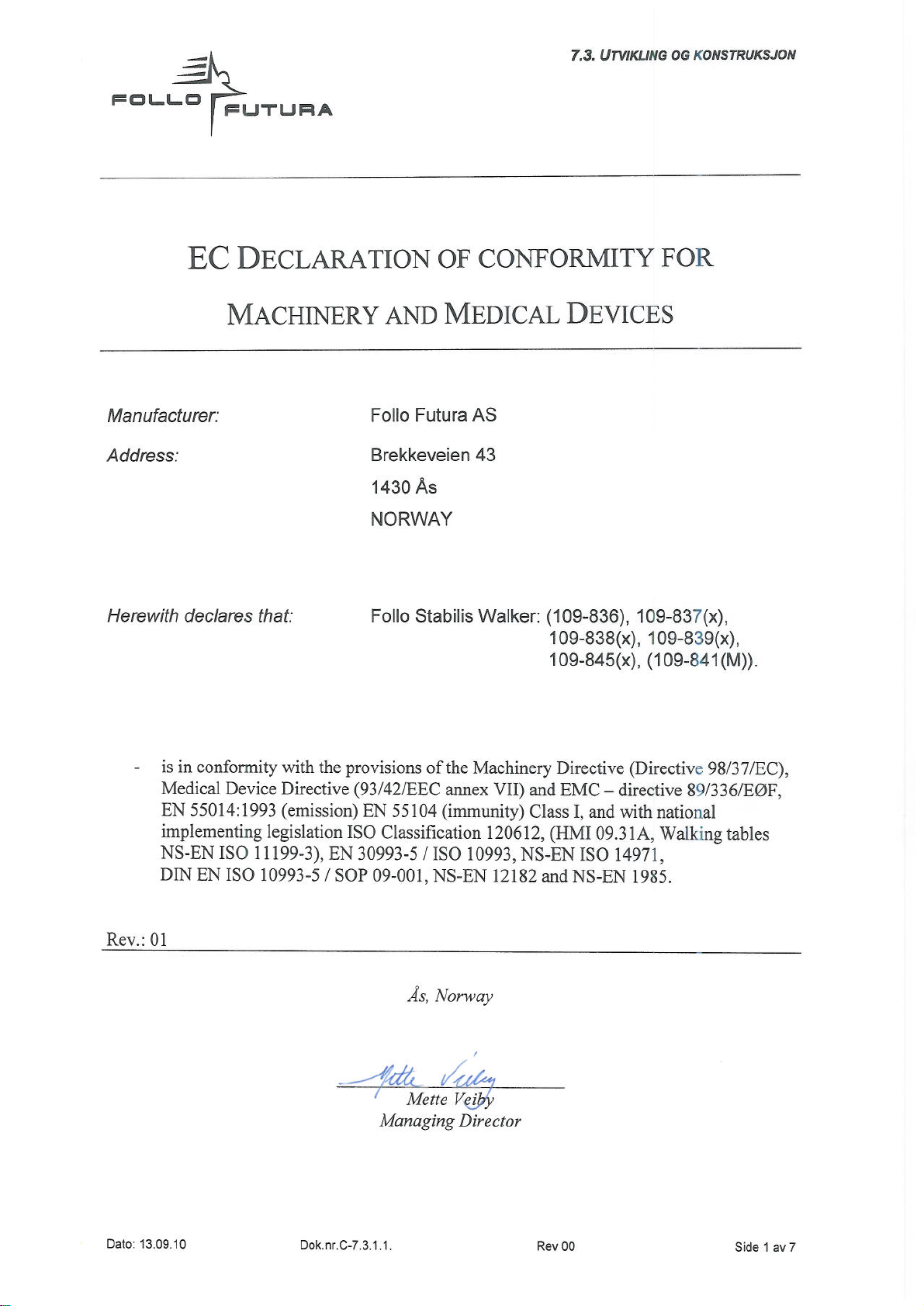
Follo Stabilis Walker 109-8xxxx
Follo Futura AS, Brekkeveien 43, N-1430 Ås
NORWAY
Pos El Gas Man Ref. no. Dim Benevnelse Description
1 0 1 1 218-108 BUNNRAMME FRAME
2 1 1 1 218-04 STATIV FRAME
3 2 2 2 218-07 TELESKOPRØR GLIDE FRAME
8 1 1 1 218-09H HÅNDTAK HØYRE HANDLE RIGHT
9 2 2 2 218-11 HYLSE TUBE
10 2 2 2 218-26 GLIDER GLIDER
11 1 1 1 595-218-34 HØYRE PUTE RIGHT REST
12 1 1 1 595-218-33 VENSTRE PUTE LEFT REST
13 4 4 4 570-001835 TANNSKIVE WASHER
14 2 2 2 562-003358 INNSLAGSMUTTER NUT
17 2 2 2 591-000200 PLASTHÅNDTAK PLASTIC HANDLE
18 2 2 2 572-001947 Ø10,2 NYLON SKIVE WASHER
19 2 2 2 218-18 POM HYLSE TUBE
20 2 2 2 591-000753 GL 32 PLASTINNSATS PLASTIC PLUG
21 2 2 2 532-004310 Ø100 HJUL U/BREMS WHEEL
22 2 2 2 532-004320 Ø100 HJUL M/BREMS WHEEL
23 1 1 1 218-09V HÅNDTAK VENSTRE HANDLE LEFT
24 0 1 0 586-000759 GASSFJÆRFESTE GAS SPRING HEAD
26 2 2 2 218-107 JUSTERINGSBØYLE ADJUSTING BOW
28 0 1 0 560-001886 M6X20 UNBRAKOSKRUE SCREW
29 2 2 2 597-218-32 FINER PLATE PLATE
32 4 4 4 560-001845 M8x20 6-KT SKRUE SCREW
34 2 6 2 572-001959 M10 UNDERLAGSKIVE WASHER
35 0 1 0 562-001850 M6 LÅSEMUTTER LOCKNUT
37 9 8 8 572-001847 M8 UNDERLAGSKIVE WASHER
38 4 4 4 560-002688 M10x35 INNV.6-KT SKRUE SCREW
40 1 1 1 590-000756 SERIEMERKE SERIAL NO.
42 0 (1) 0 586-000771 200N GASSFJÆR GAS SPRING
43 0 (1) 0 586-000772 250N GASSFJÆR GAS SPRING
45 2 2 2 562-002002 M10 MUTTER NUT
46 2 2 2 591-002841 GL 22 PLASTINNSATS PLUG
48 0 1 1 589-000101 KOMPL. KULEFESTE BALL SCREW
53 4 4 4 561-000760 Ø4x20 TRESKRUE SCREW
54 4 4 4 560-003930 M4x16 MASKINSKRUE SCREW
59 2 1 1 562-001891 M10 LÅSEMUTTER LOCK NUT
60 1 0 0 670-004172 KONTROLLBOKS CONTROL BOX
61 1 0 0 670-004173 HØYDEKONTROLL HEIGHT CONTROL
62 1 0 0 670-004175 BATTERILADER BATTERY CHARGER
63 1 0 0 670-004171 ELEKTRISK LØFTER ELECTRIC LIFT
65 1 1 1 560-003335 M10x45 6-KT SKRUE SCREW
68 2 2 2 560-000315 M10x65 6-KT SKRUE SCREW
69 2 2 2 567-003000 M6x20 RATT WHEEL
70 4 4 4 562-002528 M8 HETTEMUTTER CAP NUT
71 1 0 0 560-000691 M10x40 6-KT SKRUE SCREW
72 1 1 1 590-000247 CE-MERKE CE-LABEL
74 2 2 2 591-001964 SW 17 MUTTERHETTE NUT CAP
77 0 1 0 218-92 UTLØSERBØYLE RELEASE BOW
78 1 1 1 218-111 TOPP RAMME TOP FRAME
79 1 0 0 218-109 BUNNRAME EL FRAME EL
80 2 2 2 572-001998 Ø6/Ø22 Skjerm skive Washer
81 2 0 0 594-000464 150mm BORRELÅS HAN VELCRO HOOK
82 2 0 0 594-002780 150mm BORRELÅS HUN VELCRO LOOP
83 2 2 2 572-002000 Ø6,5 NYLON SKIVE WASHER
Pos El Gas Man Ref. no. Dim Benevnelse Description
84 2 2 2 572-003210 Ø13/20 POM skive POM washer
85 2 2 2 218-110 FILT FELT
86 2 0 0 530-117616 Ø12/Ø10 FORING BEARING
87 0 2 2 218-53 Teleskop rør / Barn Glide frame / Child
88 0 1 1 218-57 Stativ / Barn Frame / Child
89 0 2 2 532-004171 Ø75 Hjul M/brems Barn Wheel with brake / Child
90 0 2 2 532-004170 Ø75 Hjul U/brems Barn Wheel / Child
91 0 1 0 586-000770 100N Gassfjær / Barn Gas spring / Child
92 1 1 1 590-004205 www.follo-futura.no www.follo-futura.no
93 0 4 4 560-002103 M10x25 Innv.6kt. / Barn Screw / Child
94 1 1 1 590-004210 Merke innendørs bruk Label indoor use
95 1 1 1 590-004220 Merke maks bredde Label max width
96 1 1 1 590-004230 Merke maks vekt Label max weight
98 2 2 2 576-003324 Ø3x20 Spennstift Bolt
99 4 4 4 562-002008 M4 Klomutter Nut
140 0 0 1 218-23 Ø16 Teleskopbolt Glide frame
141 0 0 1 40000-84-04 Glidehylse Tube
142 0 0 1 40000-84-03 Låsehylse Lock shell
143 0 0 1 567-002996 M10x20 Låsespak Locking handle
144 0 0 1 218-22 Styrerør Tube
145 0 0 1 218-56 Teleskopbolt / Barn Glide frame / Child
146 0 0 1 218-55 Styrerør / Barn Tube / Child
17/04/18
Side 10
Rev: 21

Follo Stabilis Walker 109-8xxxx
Follo Futura AS, Brekkeveien 43, N-1430 Ås
NORWAY
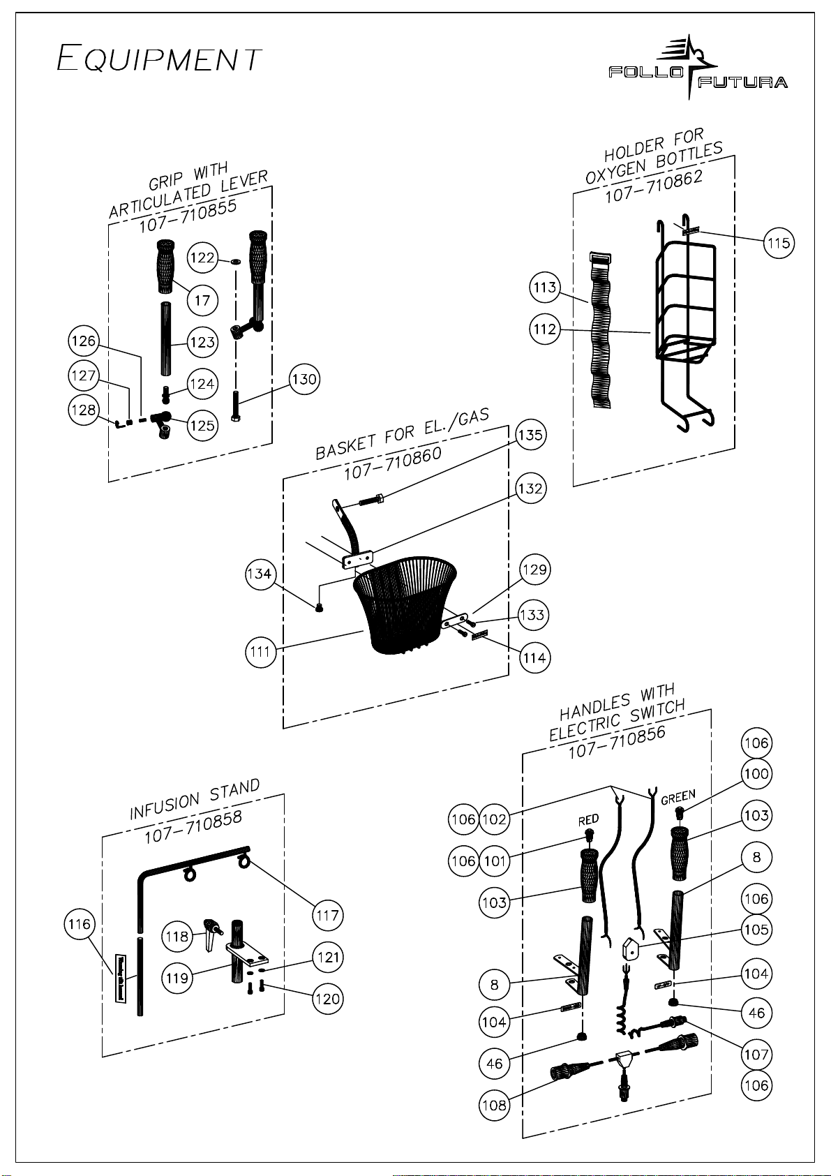
Pos Ant/Qty Ref. no. Dim Benevnelse Description
100 1 679-000101 GRØNNBRYTER GREENSWITCH
101 1 679-000100 RØD BRYTER RED SWITCH
102 2 640-000100 SORT LEDNING CABLE
103 2 218-38 PLASTHÅNDTAK PLASTIC HANDLE
104 1 599-000658 KLISTREMERKER
A
DHESIVE T
A
PE
105 1 679-000200 KOBLINGSBOKS CONNECTION BOX
106 1 599-000657 KOBLINGSSKJEMA DIAGRAM OF CONNECT
107 1 640-000101 SPIRALLEDNING SPIRAL CABLE
108 1 640-000102 FORDELINGSLEDNING DISTRIBUTE CABLE
109 2 M6 MUTTER NUT
110 1 KURV HOLDER FRAMEFOR BASKET
111 1 499-000662 KURV BASKET
112 1 107-710862 OKSYGENFLASKEHOL OXYGEN BOTTLE HOLD.
113 2 218-99 BELTE BELT
114 1 590-000410 2,5 kg MAX LAST FOR KURV LABLE BASKET
115 1 590-000411 3,8 kg MAX LAST FOR OKSYGENH. LABLE , OKSYGENBOTTLE
116 1 590-000412
A
DVARSEL MOT TILTING WARNING TILT HAZARD
117 1 499-000686 INFUSJ.HOLDER,BØYL INFUS. HOLDER, ARM
118 1 567-003925 HÅNDTAK M8x30 LOCK HANDLE
119 1 218-51 INFUSJ.HOLDER,FESTE FASTEN F/INFUSI.HOLDER
120 2 560-001886 M6x20 INNV. 6-KT SKRUE SCREW
121 2 572-000759 Ø6 SKIVE WASHER
122 2 570-003321 Ø10 SPRENG SKIVE SPRING WASHER
123 2 499-000850 RØR TUBE
124 2 579-000018 M10 KULESKRUE BALL SCREW
125 2 499-000853 STILLBART FESTE
A
DJUSTABLE FASTEN
126 2 599-000857 TRYKKSTANG PIN
127 2 560-003720 M10x10 SETTSKRUE LOCK SCREW
128 2 579-000018 LÅSESPLINT SAFETY PIN/CLIP
129 1 BRAKETT BRACKET
130 2 M6x20 SKRUE SCREW
131 1 DISTANSEBRIKKE DIST. PLATE
132 1 218-98 KURVHOLDE EL, GASS BASKET FRAME, EL, GAS
133 2 560-002234 M6x16 SKRUE SCREW
134 1 591-002578 GL 16 PLASTINNSATS PLASTIC PLUG
135 1 560-000367 M10x50 SKRUE SCREW
17/04/18
Side 11
Rev: 21
17/04/18
Side 12
Rev: 21

Parts Included: 2 Screws, 2 Nuts, 6 Wash-
ers, 1 Plate, 1 Mounting Tube and 1 Basket.
Mounting tube plate is threaded.
Tools required: Phillips screwdriver and
adjustable wrench.
Attach plate to Mounting Tube:
Attach washer to screw and insert through the
mounting plate. Attach washer to the screw
at the back of the basket and screw into the
threaded hole of the Mounting Tube.
Attach Nuts to Mounting Tube:
Attach washers and nuts to screws. Slide
the mounting tube to the top as shown, and
tighten nuts. Assembled Basket
Mounting Basket to EVA Walker:
Remove nut that attaches the pneumatic release
handle. Attach Basket Mounting Tube. Replace
nut and tighten.
Basket attached to the front of the EVA
Walker
Basket w/ Bracket Assembly Instructions
17/04/18
Side 13
Rev: 21
Table of contents
Other FOLLO FUTURA Mobility Aid manuals


