FONESTAR MPX-4088 User manual

MPX-4088, MPX-400MIC, MPX-410ES,
MPX-420V, MPX-430VS AND MPX-440X
AUDIO MATRIX
INSTRUCTION MANUAL

EN
- 2-
We take this opportunity to thank you for buying this product.
We recommend you read the instruction manual before switching on the machine and follow the instructions
that are given. Keep the manual for future reference.
SECURITY AND THE ENVIRONMENT
ELECTRICAL SECURITY
Check that the current in the mains connection where the machine is to be installed corresponds to the
power supply of the machine.
To avoid damaging the equipment, electrical shocks, fire or physical injury when you connect or disconnect
the equipment from the power supply, pull the plug firmly out of the mains socket holding the plug, never the
cable.
Always do this with dry hands.
Keep the power supply cable far from sources of heat. Do not put heavy objects on top of it or change it.
Clean dust and dirt off the power supply cable regularly.
Do not open the machine; you could get an electric shock.
CAUTION
While installing the machine, make sure it is switched off and unplugged.
Do not open the machine. Touching the internal parts is dangerous and you could receive an electric shock.
The machine must not be splashed or dripped on. Never place recipients with liquid inside on the machine.
Do not place anything inside the machine.
LOCATION
Place the equipment on a horizontal surface with enough space around it to allow ventilation.
Avoid direct sunlight, heat sources and excessive dust.
Do not place the machine near magnetic fields or static electricity.
Do not use surfaces which vibrate or receive impact.
Do not pile machines on top of one another.
VENTILATION
Never block or cover the ventilation slits on the machine.
Do not expose it to direct sunlight or place it near sources of heat.
PERIODS OF INACTIVITY
When the machine is not going to be used for a long period of time, disconnect it from the mains.
If you are using an adapter, take into account that it will continue using electricity even if the machine is
switched off. If it is not going to be used for a long period of time, disconnect it from the mains.
THE ENVIRONMENT
To save energy, switch the machine off when you are not going to use it for a long time. The machine could
contain substances that are harmful to the environment or human health. To minimize the effect of these
substances the machine must be correctly managed and recycled when you decide to dispose of it.
When you dispose of it remember: it cannot be thrown into a conventional rubbish bin.
If it contains or uses batteries, these must be disposed of separately.
The machine (without batteries) must be disposed of correctly. Put it in a container specially intended for the
collection of electronic and electrical appliances, at the dump or hand it over to the dealer when you purchase
similar equipment, so that the dealer can dispose of it correctly (at no added cost).

SIGNIFICANCE OF THE SYMBOLS ON THE MACHINE*
The symbol formed by the expression “Class 1 laser product” written in a rectangle
indicates that visible or invisible laser radiation could be produced. Avoid direct exposure
to the laser.
The symbol formed by a ray of lightening inside a triangle shows that the machine has
connection terminals or a circuit with areas with a current which could cause an electric
shock, even in normal working conditions.
The symbol formed by an exclamation mark in a triangle shows that the instruction manual
must be referred to for information on how the machine works and its use.
The symbol formed by one square inside another square shows that the machine has
double electrical insulation.
The European Community symbol shows that the machine complies with the current
European Union legislation, as well as its transposition to local legislation.
The symbol of a rubbish bin crossed out and over a horizontal line shows that when the
product is disposed of it must be done properly, placing it in a special selective electronic
and electrical equipment container or through a dealer when purchasing a similar product,
at no additional cost. It also shows that the machine was put on the market after 13th
August 2005 (European Community Directive 2002/96/CE of Electrical and Electronic
recycling, and its Spanish equivalent R.D.208/2005).
In accordance with what is set out in the aforementioned decree, FONESTAR is registered
in the RAEE (Registro de Aparatos Eléctricos y Electrónicos) in a special section REI
(Registro de establecimientos Industriales), with the entry number 001851.
*It is possible that some of these symbols do not appear on the machine.
EXEM TION OF LIABILITY
The characteristics of the equipment and the content of the manual can change without forewarning.
FONESTAR, S.A. does not assume responsibilities regarding the inappropriate use of the equipment or the
information supplied in this instruction manual, and specifically disclaims any implied liability for marketability
or fitness for any other use.
All rights reserved by FONESTAR, S.A.
- 3-
EN

DESCRI TION
The model M X-4088 is an audio matrix with 8 analogue input channels to 8 output zones and 4 configurable
digital channels.
It has 8 analogue input channels to 8 output zones and 4 configurable digital channels. Musical source
selection, volume and equalization control for each zone through PC software or via the optional zone controls
mod. M X-420V or M X-430VS. DSP function in inputs/outputs, priority control and feedback suppressor.
Priority paging using optional microphone with zone selector mod. M X-400MIC.
A highly versatile system which is suitable for installations of any size, allowing music to be selected in each
zone. Perfect for commercial installations, conference rooms, etc.
CONTROLS AND FUNCTIONS
FRONT ANEL
1.- LCD DIS LAY: information display:
a.- Device name.
b.- Selected preset.
c.- Software version.
d.- Connection status between PC and device. If the connection is
correct, both icons will flash alternatively.
e.- DSP indicator. Should a problem occur “DS !” will be displayed.
f.- Device ID number. It is obtained automatically when switched on.
2.- ANALOG IN UT: LED analogue input indicators:
-SIGNAL: indicates signal presence in the corresponding input channel.
-CLI : indicates signal saturation in the corresponding input channel.
3.- RD IN UT: digital input LED indicators:
-SIGNAL: indicates signal presence in the input channel.
-CLI : indicates signal saturation in the corresponding input channel.
4.- ANALOG OUT UT: LED analogue output indicators:
-SIGNAL: indicates signal presence in the input channel.
-CLI : indicates signal saturation in the corresponding output channel.
5.- RD OUT UT: digital output LED indicators:
-SIGNAL: indicates signal presence in the corresponding output channel.
-CLI : indicates signal saturation in the corresponding output channel.
6.- STATUS:
-FAULT: indicates a fault with the DSP.
-COM: provides information about the communication between the PC and the device. A light flashes
when there is data transmission between them. It remains switched off if there are communication
problems.
-OWER: matrix LED power indicator.
- 4-
EN

REAR ANEL
1.- 100-240 V AC power supply.
2.- Ethernet port. RJ-45 connector.
3.- RC-NET IN/LINK: input/output for interconnection of several M X-4088 devices. Connect the LINK
output to the IN input of the next matrix and so on with the rest of the matrices up to a maximum of 16
matrices, 192 inputs and 192 zones. The matrices are configured using the PC software. RJ-45
connector.
4.- RD 9/10 - 11/12: ports corresponding to the digital input and output channels, 9/10 and 11/12. They
allow the connection of models M X-400MIC, M X-410ES, M X-420V, M X-430VS for sending and
receiving of control and digital audio signals. RJ-45 connector.
5.- RELAY: contact closures that can be controlled individually using PC software. They can be used as
switches for other electric devices. Euroblock terminals.
6.- IN UT/OUT UT (1-8): balanced analogue audio input/output euroblock terminals. 48 V phantom power
supply available via PC software.
7.- FUSE: AC power supply protective fuse.
8.- LAN/RC-NET: allows the type of communication to be selected in the LAN port (2) between, TCP/IP in
LAN position or RS-485 in RC-NET position.
9.- RS-232: euroblock terminals to control via the series port.
ST CABLE FOR RD ORTS
The RD ports transmit and receive AES3 Plus control signals. Below, the PIN-OUT is shown for an RJ-45
connector and STP cable.
Note: do not connect an RD port to a router, the router could be damaged.
- 5-
EN

EN
- 6-
CONNECTION
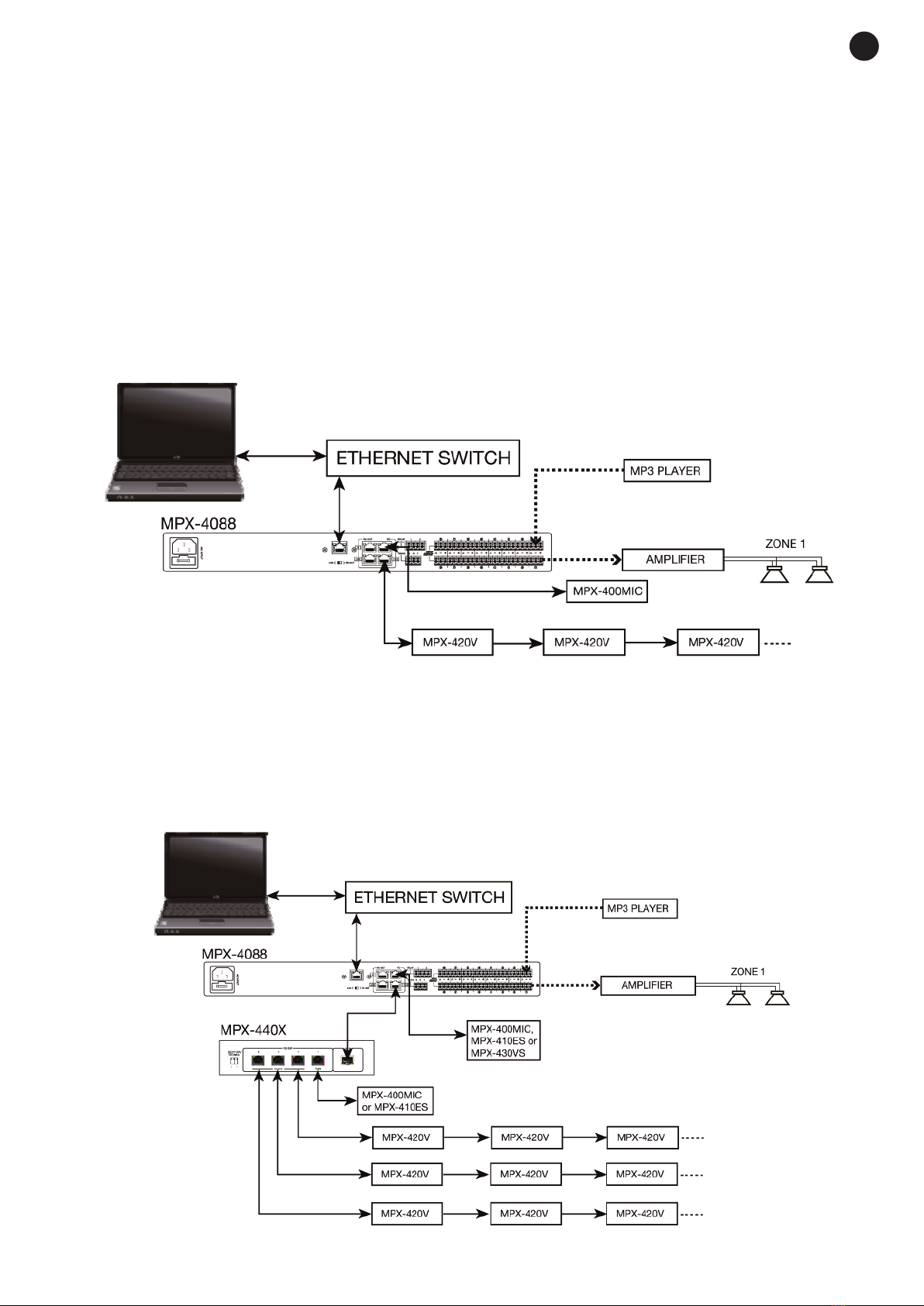
CONNECTION OF BALANCED AUDIO IN UTS 1 TO 8 AND REMOTE ZONES
Connect the analogue audio sources/microphones to the inputs 1 to 8 on the rear panel of the mod.
MX-4088. The order in which the inputs are connected will allow their selection for each of the zones via
software or zone controls.
If the zones are equipped with the remote audio input/output control mod. M X-410ES, it is possible to
connect the source directly to the microphone or line input, corresponding to the 9/10 or 11/12 lines
according to which RD port on the M X-4088 matrix it has been connected to. Each matrix supports a
maximum of two M X-410ES connected and operating at the same time.
CONNECTION OF MICRO HONES WITH ZONE SELECTORS
Connect the microphones with zone selector mod. M X-400MIC, up to a maximum of 2 units, to the RD 9/10
or 11/12 inputs on the rear panel of the mod. M X-4088, using shielded Cat 5e cable with RJ-45 connector.
Note: it supports the connection of two M X-400MIC microphones maximum per matrix, for non-
simultaneous use.
ZONE OUT UT CONNECTION
Each matrix mod. M X-4088 has 8 independent zones with balanced line level output for the connection of
a power amplifier or amplifier per zone. Connect the output of each of the zones to a line level input of a
corresponding power amplifier. Control the output volume with the PC software or using the remote control
mod. M X-420V or M X-430VS and then regulate the level of the power amplifier in order to achieve a
suitable level of volume in the loudspeakers in the zone. It is possible to extend the output zones to 12 with
the connection of 2 M X-410ES audio input/output controls or 2 M X-430VS zone controls with audio
output.
CONNECTION OF ZONE CONTROLS
Each of the output zones can be controlled remotely using the controls mod. M X-420V or mod.
M X-430VS. These controls allow the selection of any of the selectable inputs 1 to 12 of the matrix mod.
M X-4088, as well as the regulation of the volume of each remote zone. The M X-430VS control
incorporates two audio outputs corresponding to the channels 9/10 or 11/12 according to the RD port on the
M X-4088 matrix to which it has been connected.
Connect the M X-420V or M X-430VS control with Cat 5e or higher cable, RJ-45 connector to the RD ports
9/10 or 11/12 on the matrix.
Note: up to 8 M X-420V controls can be connected in series as a maximum, for a maximum distance of 150
meters with shielded Cat 5e or higher network cable.
GENERAL CONNECTION RECOMMENDATIONS
Make the connections with the matrix and all the components of the audio system switched off and
disconnected from the power supply. Always begin with the volume controls at their minimum. Move the
controls slowly.
Firstly, connect the audio sources to the inputs. A bad connection can cause noise and interference. Use
suitable cables that are not excessively long to make the connections: shielded cables, preferably low
capacity.
Connect remote controls mod. M X-420V or M X-430VS in the required zones and the microphone with
zone selector mod. M X-400MIC, the remote audio input/output control mod. M X-410ES or the extender
M X-440X to the matrix RD ports using Cat 5e or higher cable.
Connect a power amplifier to the OUTPUT of each zone you are going to use. 100 V line or low impedance
4-8 Ω amplifiers can be used depending on the type of loudspeakers that are going to be connected. Once
the connections have been made, connect the devices to the mains supply and switch them on. After use,
do not forget to switch them off and disconnect the device from the mains supply.

CONNECTION EXAM LES
With the audio matrix mod. M X-4088 it is possible to configure systems of 12 to 192 zones. The basic
system allows connection of up to a maximum of 12 inputs and 12 outputs per matrix. With the optional mod.
M X-450D (DANTETM module), the interconnection of up to 16 M X-4088 matrices is possible for a total of 192
inputs and 192 outputs, making it compatible with other DANTETM systems. The configuration and allocation of
inputs and outputs can be performed using the PC software or the M X-420V or M X-430VS zone controls.
The matrix has up to 8 analogue audio inputs, 8 zone outputs and two RD ports with 4 audio input/output
channels for the connection of models M X-400MIC, M X-410ES, M X-420VS or extending the RD ports
with the mod. M X-440X.
Below, the different connection configurations are shown:
CONFIGURATION 1
- RD port 9/10: M X-400MIC microphone with zone selector for priority paging.
- RD port 11/12: M X-420V zone controls, without exceeding a maximum of 8 devices in series and a
distance of 150 meters for a shielded Cat 5e or higher cable.
CONFIGURATION 2
EN
- 7-

EN
- 8-
With the port extender mod. M X-440X connected as shown in the previous diagram, 4 audio input/output
channels are available corresponding to the audio port of mod. M X-440X and the RD 9/10 matrix port and
3 control ports on the mod. M X-440X for the connection of M X-420V zone controls. Up to a maximum of
8 units of the model M X-420V can be connected in series by port and a maximum cable distance of 150
meters for a shielded Cat 5e or higher network cable.
CONFIGURATION 3
With the two M X-4088 matrices connected as shown in the diagram above, up to 16 analogue audio inputs
can be connected to 16 selectable zones, 4 M X-400MIC microphones with zone selectors or 4 M X-410ES
audio input/output controls, plus the M X-420V or M X- 420VS zone controls. With the optional M X-450D
model, the interconnection of up to 16 M X-4088 matrices is possible for a total of 192 inputs and 192 outputs,
making it compatible systems with other DANTETM systems.

EN
- 9-
CONFIGURATION AND CONTROL SOFTWARE
The matrix M X-4088 is configured using PC software. In order to download the software, access our
website fonestarpro.com and find the product M X-4088. Then, open the “Software” tab to download the
file in your computer and install the software. This software is compatible with Windows 7 or higher. The
software has two connection modes for the configuration of the matrix.
1.- Daisy chain network mode: allows configuration of the matrix M X-4088, as well as the optional models
M X-400MIC, M X-410ES, M X-420V and M X-430VS. In this edition mode, the PC and the matrix
M X-4088 must be connected directly by RJ-45 cable and the LAN/RC-Net selector located on the rear
panel of the matrix, must be in the LAN position.
It is necessary to establish the IP address of the matrix. To do so, click on the SETUP button and, then,
on SCAN to begin the automatic search for the IP and MAC address of the M X-4088 matrix.

Select the line with the IP and MAC address of the M X-4088 matrix and click on APPLY. Then, click on
CONNECT and the STATUS indicator should turn green. Add the devices located in the sidebar by
dragging them into the grey area.
Double click on the required device module to access the edition mode.
Note: when several matrices are connected in cascade, the LAN/RC-Net connector must be in the LAN
position on the matrix that is directly connected to the PC, and in the RC-Net position on the rest of the
matrices that are connected to each other. To access the configuration of each device, it is necessary to
establish the device’s ID manually by right-clicking on the device to be configured and accessing “Change
Device ID”.
2.- Star network mode: allows the configuration and individual control of several M X-4088 matrices
connected to the same router. In this edition mode, the PC and the M X-4088 matrix must be connected
to the router with RJ-45 cable and the LAN/RC-Net selector located on the rear panel of the matrix must
be in the LAN position.
In this edition mode, the system automatically detects the M X-4088 matrices connected to the network
for their configuration and control.
- 10 -
EN

EDITION MODE
M X-4088
The edition mode of the M X-4088 allows real-time editing of input/output signal processing parameters,
allocation of sources to zones, attenuation of signal level inputs, feedback cancellation, auto-mix, presets to
be saved and loaded, relays to be activated/deactivated, the device name to be changed and factory values
to be restored. By default, the Input DS Channel tab is displayed.
IN UT DS CHANNEL
2.- EX /GATE MODULE:
Add dynamic to the signal for each input channel. When the input signal is below the
threshold, the expander amplifies it with the ratio value adjusted. If the signal is above
the threshold, the output remains identical. By adjusting the ratio value to the maximum
(Limit), the expander becomes a noise gate.
a.- raphic display of EX /GATE module.
b.- Release: expander release time when the signal goes above the threshold.
c.- Ratio: amplification ratio between input signal and amplified signal.
d.- Threshold: threshold value, the signal below this value will be amplified according to the selected
amplification ratio.
e.- Attack: expander reaction time when the input signal is below the threshold value.
f.- Bypass: the input signal is not processed and is diverted to the next processing module.
g.- Default: resets the default values of the EX /GATE module.
- 11 -
EN

2.- HANTOM OWER SU LY MODULE
a.- DC 48 V: allows the phantom power supply of each input channel to be
activated/deactivated.
b.- Microphone Sensitivity: allows the microphone sensitivity to be adjusted.
c.- olarity: allows the input signal phase to be inverted 180º.
3.- IN UT/OUT UT CHANNELS
a.- Input/output channel selector (CH1 - CH12).
b.- Mute: silences the corresponding input/output channel.
c.- Signal level digital fader (-80 a +15dBu).
d.- LED indicator of input/output channel signal level.
e.- Displays the gain value applied to the input/output channel.
4.- DELAY MODULE
a.- Delay: delay applied to the signal from the corresponding input/output
channel, in ms.
b.- Bypass: the input signal is not processed and is diverted to the next
processing module.
5.- EQUALIZATION MODULE
High and low pass filters to eliminate frequencies above or below the
established cutoff frequency.
a.- Freq.: cutoff frequency.
b.- Type: type of filter applied: Bessel, Linkwitz or Butterworth.
5-band parametric equalization. Allows the input signal spectrum to
be modified graphically or by entering the required values manually.
c.- Frequency: central frequency.
d.- Qfact: filter quality factor. The greater the value, the smaller the range of frequencies that are affected.
e.- Flat: all the equalization parameters are restored to their original value.
f.- Bypass: the input signal is not processed and is diverted to the next processing module.
g.- Gain: gain elevation or attenuation in the established central frequency.
h.- Type: type of filter; peak, low pass or high pass.
i.- Bypass 1~5: allows the processing of filters 1 to 5 to be cancelled without using the general bypass.
6.- COM RESSION MODULE
Limits the dynamic of the signal for each input channel. When the signal exceeds
the threshold, it is compressed in a ratio greater than 1. Below the threshold, the
compressor does not modify the signal. By adjusting the ratio to its maximum
value (Limit), the compressor becomes a limiter.
a.- raphic view of the Compressor module.
b.- Threshold: threshold value, above this value the signal will be compressed
according to the selected compression ratio.
c.- Attack: compressor reaction time when the input signal is above the
threshold level.
d.- Ratio: compression ratio between the input signal and the compressed
signal.
e.- Release: release time of the compressor when the signal is above the
threshold value.
f.- Flat Comp: sets the Compressor module default values .
g.- Bypass: the input signal is not processed and is diverted to the next processing module.
- 12 -
EN

MATRIX
With the MATRIX function, the inputs are allocated to the outputs. By clicking on the grey rectangles, they
turn green, indicating the correct allocation of the input channel to the chosen output.
IN/OUT 1~8 correspond to the analogue audio inputs/outputs available on the rear panel.
IN/OUT 9~12 correspond to the digital audio inputs/outputs (RD ports) for models M X-400MIC,
M X-410ES and M X-430VS, available on the rear panel.
IN/OUT NET 1~8: correspond to the broadcast inputs/outputs.
OUT UT DS CHANNEL
The same menu as the DSP Input Channel but without the expander module and phantom power supply. The
parametric equalization is 8-band instead of 5.
DUCKER
The DUCKER function allows one or several channels to be attenuated depending on the signal level of the
channels with priority.
Source Select
1.- Local Input: selection of input channels with priority.
- 13 -
EN

BGM Setting
2.- Local input: selection of input channels to be attenuated.
3.- Network Input: selection of broadcast inputs to be attenuated.
Ducking Controller
4.- Threshold: attenuation threshold.
5.- Depth: attenuation depth.
6.- Attack: reaction time to attenuate the selected channels.
7.- Release: release time of the selected channels.
8.- Default: resets the default values.
9.- Bypass: the input signal is not processed and is diverted to the next processing module.
FEEDBACK CANCELLER FBC
The Feedback Canceller function automatically eliminates the feedback produced by microphones to nearby
loudspeakers.
FBC Input Select
1.- Local Input: selection of input channels to be processed.
2.- Network input: selection of broadcast input channels to be processed.
FBC Setting
3.- Filter Release: dynamic filter release time after processing the signal.
4.- FBC Mode: application mode, for music or for speech.
FBC Setup
5.- Static Filters Setup: volume configuration to achieve feedback.
6.- FBC filters: 24 feedback cancellation filters.
7.- Clear Dynamic Filters: restarts dynamic filters.
8.- Clear All Filters: restarts all filters, static and dynamic.
9.- Bypass: the input signal is not processed and is diverted to the next processing module.
- 14 -
EN

FBC Output Assign
10.- Local Output: output channels corresponding to the inputs selected for processing.
11.- Network output: broadcast output channels corresponding to the inputs to be processed.
The configuration of the FBC is manual. It consists in finding the resonance frequencies to be eliminated.
Once the frequencies have been found, the system will automatically decide on the suitable filters.
In order to configure the FBC, the microphones must be connected and open. The FBC (4) fader must be
moved until feedback is reached. When the system detects feedback, the indicators 1 to 24 turn red for
static filters and green for dynamic filters.
AUTOMIXER
The AutoMixer function reduces the level of a microphone when it is not being used, ideal for conference
rooms, theatres, etc.
This function can be combined with the Ducker function, by doing so also establishing priority.
1.- Local input: selection of input channels to be processed.
Active Time
2.- ON/OFF: activates/deactivates the attenuation time.
3.- Sets the attenuation time.
- 15 -
EN

SAVE/LOAD
From the SAVE/LOAD tab, configurations can be saved and loaded as presets. This data can be saved in the
internal memory of the matrix, as well as in the PC. The memory of the M X-4088 matrix has a capacity for
a total of 16 presets.
1.- Import All resets: imports the presets from the M X-4088 matrix to a file in the PC.
2.- Window showing the list of presets and their position in the memory.
3.- Export All resets: exports all the presets from the PC to the M X-4088 matrix.
4.- Device/Local C: selects in order to act on the matrix memory or that of the PC.
5.- Copy from: channel from which the copy is made.
6.- Selection of channels to which the copy is applied.
7.- Selection of all channels simultaneously.
8.- Save: saves the current configuration of the M X-4088 matrix as a preset in the PC or matrix memory.
9.- Delete: eliminates a preset from the M X-4088 matrix.
10.- Load: loads a preset from a PC file or from a matrix memory.
11.- Copy: makes a copy of the selected channels.
- 16 -
EN

SYSTEM
1.- Relay Control: controls the contact closures on the rear panel of the M X-4088 matrix. Press the button
to close the relay(s): the buttons will turn green. Press the button(s) again in order to open the relays.
2.- Restore Default Settings: restores the matrix to the default configuration.
3.- Reset to Factory Setting: eliminates all the configurations, including the default configuration.
4.- Device name: displays the name of the device.
5.- Change Device Name: allows the name of the device to be changed.
6.- assword setting: allows the lock password to be changed.
7.- Lock System: allows the device to be locked/unlocked.
Note: the default password is 8888.
- 17 -
EN

M X-400MIC
In Daisy Chain connection mode, the edition mode for the M X-400MIC microphone with zone selector,
has the following functions:
1.- Max. Zone Setting: maximum number of paging zones, from 12 to 192.
2.- Zone Setting: possibility of establishing names for each zone.
3.- Selection of zone number assigned to the output of each zone.
4.- riority: selects the priority of this microphone within the system, 1 to 8.
5.- Mic. Volume: allows microphone volume to be adjusted.
6.- Load reset: allows the saved configuration to be loaded.
7.- Save preset: saves the current configuration.
8.- Load from Device: loads the configuration of M X-400MIC.
9.- Save to Device: saves the current configuration in the M X-400MIC.
10.- Default: sets the default configuration.
11.- Chime time: sets the duration of the chime, from 0.5 to 12 seconds maximum.
12.- Chime volume: allows the chime volume to be adjusted.
13.- Master volume: allows the general volume of the M X-400MIC to be adjusted.
14.- Device name: allows the device name to be changed to one that is easily identified.
M X-410ES
In Daisy Chain connection mode, the edition mode for the audio input/output control M X-410ES, allows the
device name to be changed within the system.
M X-420V
In Daisy Chain connection mode, the edition mode for the remote zone control M X-420V, allows the device
name to be changed within the system.
M X-430VS
In Daisy Chain connection mode, the edition mode for the remote zone control M X-430VS, allows the
device name to be changed within the system.
- 18 -
EN

O TIONAL MODELS FOR MATRIX M X-4088
M X-400MIC
DESCRI TION
The model M X-400MIC is a microphone with zone selector and chimes for the audio matrix model
M X-4088. The zones can be selected individually or all at the same time.
There is the option to personalise the zone names, microphone volume, volume and chime duration, using
physical controls or PC software.
CONTROLS AND FUNCTIONS
FRONT ANEL
1.- XLR connector for electret condenser.
2.- LCD information display, showing the zones, volume and ID number.
3.- COM/BUSY: LED communication status indicator:
-COM: correct communication between the M X-4088 matrix and the M X-400MIC microphone.
-BUSY: communication problem between the M X-4088 matrix and the M X-400MIC microphone.
4.- SIGNAL/CLI : LED signal indicators:
-SIGNAL: indicates signal presence.
-CLI : indicates signal saturation.
5.- VOL/ALL ZONES: microphone volume control for selected zones. One press of the button, selects all
zones. A long press of this button, accesses the edition mode of the M X-400MIC.
6.- ZONE SELECT/ : selects one or several zones by turning the button to the left or right and pressing
to select them.
7.- TALK: when the button is pressed, the chime is played in the selected zones and the LED ring on the
microphone lights up indicating that it is possible to speak.
Note: in order to perform a factory reset, the buttons VOL/ALL ZONES and ZONE SELECT/ must
be pressed and held for more than 3 seconds.
- 19 -
EN

REAR ANEL
1.- RD: RD port for connection to matrix mod. M X-4088.
2.- .: mini USB port to load customized chimes in MP3. To set a different chime, connect the mini USB
port to your PC and replace the chime with the one of your choice. The maximum duration of the chimes
is 4 seconds.
INSTALLATION
Insert the RJ-45 connector in the RD port on the rear panel and the other end of the connector in the RD port
9/10 or 11/12 of the matrix mod. M X-4088.
Note: the total distance of the cable must not exceed 150 meters for an STP Cat 5e cable.
M X-410ES
DESCRI TION
The model M X-410ES is an audio input/output remote control for the matrix mod. M X-4088, with 2
input channels for Mic. or 2 x RCA. Balanced XLR microphone input and 2 euroblock balanced audio
outputs selectable via the control module M X-420V, M X-430VS or PC software.
CONTROLS AND FUNCTIONS
FRONT ANEL
1.- A/B RCA: line level analogue inputs allocated to channels 9 or 10 (A) and 11 or 12 (B) according to the
RD port connection 9/10 or 11/12 in the M X-4088 audio matrix.
2.- HANTOM 48 V: phantom power supply connector for XLR microphone.
3.- IN UT: signal indicators for channels A/MIC and B.
-SIGNAL: indicates signal presence in the corresponding channel.
-CLI : indicates signal saturation in the corresponding channel.
4.- MIC: XLR connector for the microphone input. When the microphone is connected, replace the input
channel A of the RCA connection.
5.- MIC LEVEL: adjusts the microphone volume level.
- 20 -
EN
Other manuals for MPX-4088
1
This manual suits for next models
5
Table of contents
Other FONESTAR Matrix Switcher manuals