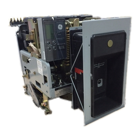
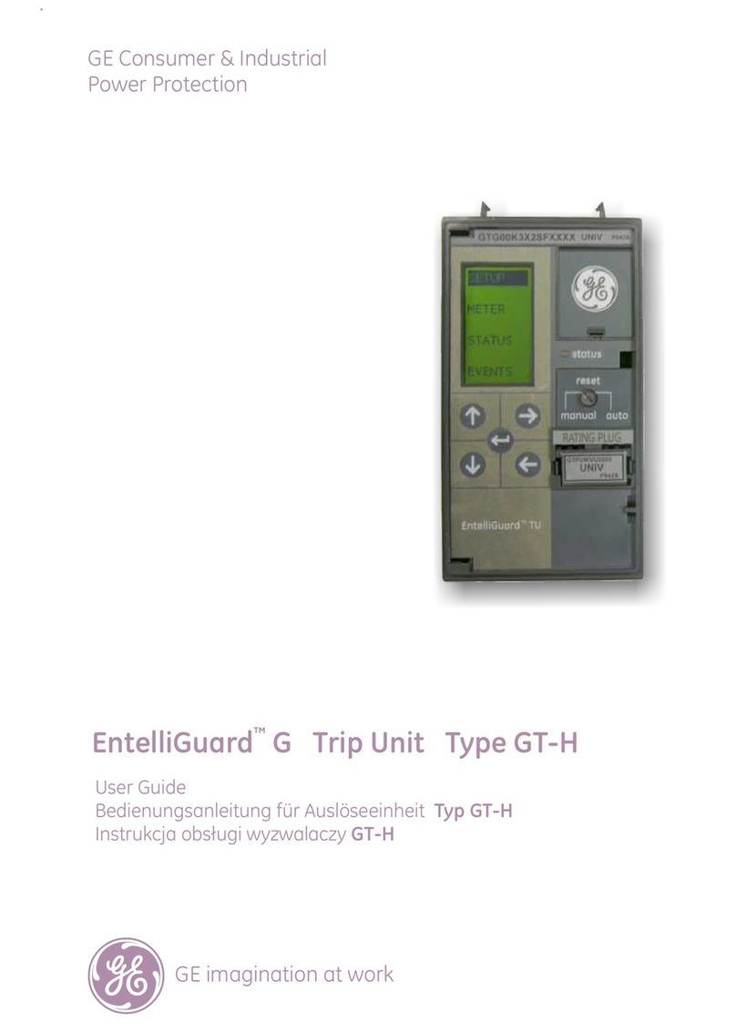
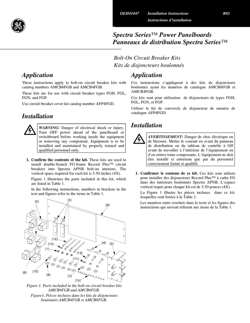
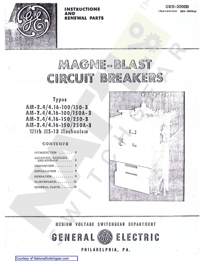
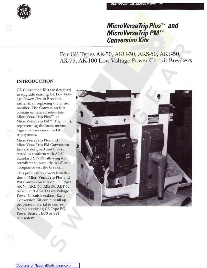
GE EntelliGuard G User guide

Contents
Section Page
1 Introduction . . . . . . . . . . . . . . . . . . . . . . . . . . . . . . . . . . . . . . . . .1
2 Features and Characteristics . . . . . . . . . . . . . . . . . . . . . . . .3
3 EntelliGuard TU Trip Unit System . . . . . . . . . . . . . . . . . . . . .7
4 Accessories . . . . . . . . . . . . . . . . . . . . . . . . . . . . . . . . . . . . . . . .31
5 Catalog Numbering Guide . . . . . . . . . . . . . . . . . . . . . . . . . .41
6 Application Data . . . . . . . . . . . . . . . . . . . . . . . . . . . . . . . . . . .47
7 Physical Data . . . . . . . . . . . . . . . . . . . . . . . . . . . . . . . . . . . . . .55
8 Standards and References . . . . . . . . . . . . . . . . . . . . . . . . .57
Courtesy of NationalSwitchgear.com

1
EntelliGuard®GPower Circuit Breaker
Section 1. Introduction
EntelliGuard®Gcircuit breakers are the newest line of low voltage power circuit
breakers (LVPCBs) evolved from the exceptional designs and practices of GE legacy
breakers. EntelliGuard G breakers offer a truly global product platform that meets
industry standards throughout the Americas, Europe and Asia (ANSI, UL, CSA, IEC,
Lloyds Register of Shipping, etc.).
Breakers are available in 3 and 4 pole designs from 400A to 6400A (IEC) with fault
interruption ratings up to 150kAmps. New, state-of-the-art EntelliGuard Trip Units
enable the breakers with advanced technology that provides system protection, local
and remote monitoring, relaying and communications. EntelliGuard Trip Units may be
supplied with either Modbus or Profibus communications protocols. The breaker-
trip unit system delivers superior circuit protection without compromising selectivity
or arc flash protection. The EntelliGuard system is yet another evolution of GE’s core
competencies in reliable electric power distribution, circuit protection and safety.
EntelliGuard G breakers are the standard in GE AKD-20 Low Voltage Switchgear.
The breakers are suitable for 480vac and 600vac applications, and they provide
advanced circuit protection, limit arc fault energy and preserve system coordination
without sacrificing any of these critical functions.
ANSI®Certified
Low-Voltage
Power Circuit
Breaker
C3-7.13
C3-7.16
C3-7.17
C3-7.20
C3-7.50
UL 1066
NEMA SG3&5
UL®Listed
Insulated Case
Circuit Breaker
UL 489
NEMA AB1
CSA 22.2 NO 5.1
IEC®Rated
Circuit Breaker
IEC 60947-1
IEC 60947-2
IEC 60947-3
IEC®Extreme Atmospheric Conditions
IEC 68-2-1: Dry cold at -55°C
IEC 68-2-2: Dryheat at +85°C
IEC 68-2-30: Damp heat (temp. +55°C,
rel. humidity 95%)
IEC 68-2-52 Level 2: Salt mist
EntelliGuard G devices are available in all standard, 100% rated, ANSI, UL and IEC
ratings in both fixed and draw-out designs. Standard devices are also offered in 4
pole designs. No compromise (e.g., derating) is necessary in the system protection
scheme as the EntelliGuard G Neutral poles are fully rated. Front and rear access
connections areavailable, and all configurations can be manually or electrically
operated with multiple and redundant accessories (optional).
Device Ratings (Amperes)
Standard Current Range (A)
Envelope 1 (N, H) Envelope 2 (E, M) Envelope 3 (B, L)
ANSI/UL 400 - 2000 2000 - 3200 3200 - 5000
Courtesy of NationalSwitchgear.com

2
Section 1. Introduction
EntelliGuard G short circuit & interrupting ratings
ANSI/UL1066
UL489
Non-Automatic Circuit Breaker – ANSI Version
NOTE: GE internal quality testing requirements exceeded 20,000 mechanical operations.
Non-Automatic Circuit Breaker/Molded Case Switch – UL Version
NOTE: GE internal quality testing requirements exceeded 20,000 mechanical operations.
Type E = Sq. Rated (ICW = ICU) 400-2000A, 85kAIC @ 480/508V
Type B =Sq. Rated (ICW = ICU) 3200-6000A,100kAIC @ 480/508V
Type N = 65kAIC @ 480/508/600/635V
Type H = 85kAIC @ 480/508V, 65kAIC @ 600/635V
Type M =100kAIC @ 480/508V,85kAIC @ 600/635V
Type L = 150kAIC @ 480/508V, 100kAIC @ 600/635V
Envelope Type Amps
Short
Interrupting
Current
Rated Endurance
Minimum Mechanical
Endurance
Minimum Electrical
Endurance at 480V
Minimum Electrical
Endurance at 600V
1N800 42 12,500 10,000 7,500
1N1600 42 12,500 10,000 7,500
1N2000 42 12,500 7,500 5,000
2H3000 65 5,000 5,000 5,000
3L4000 100 5,000 3,000 2,000
3L5000 100 5,000 3,000 1,500
3L6000 100 5,000 2,000 1,000
Envelope Type Amps
Rated
Interrupting
Current
Rated Endurance
Minimum Mechanical
Endurance
Minimum Electrical
Endurance at 480V
Minimum Electrical
Endurance at 600V
1N800 42 12,500 10,000 7,500
1N1600 42 12,500 10,000 7,500
1N2000 42 12,500 7,500 5,000
2H3200 65 5,000 5,000 5,000
3L4000 100 5,000 3,000 2,000
3L5000 100 5,000 2,000 1,500
Interrupting Rating Tier UL489 Devices, ICCB Envelope 1 Envelope 2 Envelope 3
Type 240V 480V 600V 1/2S Withstand 400-2000 2500-3000 400-3000 3000 4000 5000-6000
N65,000 65,000 65,000 42,000 X X
H85,000 85,000 65,000 50,000 X X
M100,000 100,000 85,000 65,000 X X
L150,000 150,000 100,000 85,000 X X X
Interrupting Rating Tier ANSI/UL1066 Devices, LVPCB Envelope 1 Envelope 2 Envelope 3
Type 240V 480V 600V 1/2S Withstand 400-2000 3200 400-3200 3200 4000-5000
N65,000 65,000 65,000 65,000 X X
H85,000 85,000 65,000 65,000 X
E85,000 85,000 85,000 85,000 X
M100,000 100,000 85,000 85,000 X X
B100,000 100,000 100,000 100,000 X X
L150,000 150,000 100,000 100,000 X X
Courtesy of NationalSwitchgear.com

3
EntelliGuard G Power Circuit Breaker
Section 2. Features and Characteristics
EntelliGuard G at a glance
Label EntelliGuardTU Trip Unit
Secondary disconnects –
combination terminals
Padlock provision
Accessory windows
Main Screen with
Setup – allows adjustment of
settings and parameters
Meter – display full
measurement values
Status – indicates breaker
main contact position
Event log – shows history of
trip, cause,
overcurrent level
and access to
waveform capture
(optional)
Cursor-driven Setting/Selection
System
Rating Plug
Retractable handle for
manual spring charging
Detailed, factory-
assembled side
label
Breaker status contacts:
OPEN/CLOSED
Closing spring status:
CHARGED/DISCHARGED
Tamper-proof
breaker label
EntelliGuard TU
trip unit
Rating plug
Operating buttons:
ON/OFF
Spring charged indicator
Optional factory-
installed interlocks Complete, factory-assembled
catalog number
Mechanical operations
counter
Product Family Bar Code with
Manufacturing Data
Interruption Tier Color
Code (IEC only)
Voltage
Ratings
Short
Circuit
Ratings
Certification
& Standards
Current
Rating
Manufacturing Date
Courtesy of NationalSwitchgear.com

4
Section 2. Features and Characteristics
Standard and Optional Features
Short Time Rating Up to 100kA for 1 sec
Short Circuit/High Interruption Rating 150kA@600v, 100kA@690v (IEC only)
Thermal Performance ANSI C37 & UL 489 designs are 100% rated up to
40ºC when applied in recommended enclosure
sizes. IEC 60947 versions are 100% rated in free
air up to 50ºC. IP31 enclosure / switchboard rating
is based on size, recommended up to 50ºC ambient
with rear vertical bus connection.
Reverse Feed EntelliGuard G devices can be fed from top or
bottom terminals.
Two-Step Stored Energy Mechanism EntelliGuard G operates via stored energy mecha-
nisms that can be manually charged (MO) or elec-
trically charged (EO) by the Spring Charging Motor.
Closing time is less than fivecycles. Closing and
opening can be initiated remotely or via the front
cover push buttons. An O-C-O cycle is possible
without recharging. The breaker operating mecha-
nism is a trip-free and may be furnished with an inte-
grated anti-pumping system.
Field Installable Trip Units & Accessories Field-installable accessories arecommon to all
breaker envelopes.
Coils EntelliGuard G devices have provisions for 4 coils.
Twoshunt trip coils or 2 UVR coils can be mounted
along with closing coil. The closing coil is a “one-
shot” electronic closed circuit. Shunt trip (ST) coils
arecontinuous rated. Under voltage relays (UVR)
are available with a fixed time delay (50mS @
down to 50% system voltage; 20mS below 50%.
system voltage). The time delay module (TDM) is
available as a shipped-loose accessory for remote
installation (in equipment). Optional status mod-
ules for the ST, CC and UVRs provide coil via the
secondarydisconnects and trip unit.
Breaker/Main Contact Status OPEN/CLOSED,ON/OFF indication is provided on
the front cover.
Motor Operator Heavy duty, motor/gearbox unit; easily accessible.
Standard
Current Range (A)
Envelope 1
(N, H)
Envelope 2
(E, M)
Envelope 3
(B, L)
ANSI/UL 400 - 2000 2000 - 3200 3200 - 5000
Courtesy of NationalSwitchgear.com

5
Section 2. Features and Characteristics
Electrical Closing Button Located on the front cover; electrically closes breaker.
Ready to Close Indicator Provides visible indication/readiness for close
operation.
Mounting Straps/Accessories Kits are available to mount and connect fixed/
stationary breakers.
Thermal Sensing One sensor per pole continuously monitors the
temperature of the current path (optional). The
temperature sensing function monitors breaker
bus (phase) temperatures continuously at a range
of 0°C–200°C. Temperature readings are available
locally (trip unit LCD) or remotely (communications).
Auxiliary Switches (Optional) 4available designs:
•Power contacts, 3NO & 3NC (standard/included)
•Power contacts, 8NO & 8NC
•Power contacts, 3NO & 3NC + high fidelity
2NO & 2NC
•Power contacts, 6NO & 6NC + high fidelity
2NO & 2NC
Interlocks Standard interlocks include:
•Draw-out Breaker: prevents the breaker from being
closed unless it is in the TEST or CONNECT positions
•Draw-out Breaker/Main Contacts: prevents with-
drawal/removal of the breaker unless the main
contacts areOPEN. Access to the draw-out
mechanism racking screw is blocked when the
breaker is CLOSED.
•Spring Discharge Interlock: Automatically dis-
charges the closing springs when the breaker is
moved from the TEST to the DISCONNECT position.
This prevents withdrawing a breaker from the
cubicle with the closing springs charged.
(Commonly referred to as “crash.”)
Breaker Status Indicators Standard Indicators include:
•The breaker status indicator shows the condition
of the main contacts (OPEN, CLOSED).
•The status of the closing springs is indicated as
CHARGED or DISCHARGED.
•The draw-out position indicator displays whether
the breaker is in the CONNECT, TEST or DISCON-
NECT position.
•The breaker also includes a switch that provides
main contact status indication to the POWER
LEADER™ Power Management System.
Courtesy of NationalSwitchgear.com

6
Section 2. Features and Characteristics
Rejection Feature Afactory-installed rejection feature prevents mis-
matching breakers and cassettes/substructures.
This prevents (a) inserting a breaker with a lower
rating into a higher rated cassette/substructure
and (b) inserting a higher rated breaker into a
lower rated cassette/substructure.
Though-door Racking The breaker racking mechanism is accessible
through the front door and permits safely discon-
necting/withdrawing the circuit breaker without
opening the door and exposing personnel to live
parts during the process.
Padlocking Devices The padlocking device is standard on breakers
and allows up to three padlocks with 1/4" to 3/8"
diameter shanks to secure the breaker in the
OPEN/TRIP FREE position. A padlock provision on the
front panel of the cassette/substructure permits
locking the breaker in either the TEST or DISCONNECT
position with up to three padlocks.
Key Interlock Up to 4 optional key interlocks are available
(Kirk, Ronis, Profalux, Castel).
Shutters Optional lockable shutters are available
(factoryinstalled).
Carriage Position Switch This optional cassette/substructuredevice permits
local or remote indication of the circuit breaker
status (CONNECTED, TEST, DISCONNECTED, 6 sin-
gle-pole changeover contacts).
Lifting truck Optional lifting tool with separate slings is available
for all breaker sizes.
IP Covers Optional IP54 covers are available for all breaker
sizes.
Mechanical Counter Provides local record of the cumulative number of
complete breaker closing operations.
Cable Interlocks Available for fixed and draw-out breakers, these
units enable direct interlocking of EntelliGuard G
circuit breakers.
Bell Alarm Contact Available with or without a mechanical lockout
feature, the bell alarm operates whenever the
breaker trips due to a protective function.
Courtesy of NationalSwitchgear.com

7
EntelliGuard G Power Circuit Breaker
Section 3. EntelliGuard®TU Trip Unit System
The EntelliGuard TU Trip Unit offers optimum circuit
protection and optimum system reliability simulta-
neously with little or no compromise to either of
these critical functions. Reliability and safety, in
one package, at the same time, all the time.
EntelliGuard TU series trip units are available as
the standard controller for new production
EntelliGuard G ANSI/UL 1066, UL 489 and IEC circuit
breakers. EntelliGuard TU designs are also available
as direct, functional replacements for GE’s
PowerBreak®,Power Break II, WavePro®and AKR
circuit breakers. New on-board features and
communications capabilities enable equipment
enhancements, improved operational performance
and life extension programs. Performance will
vary based on associated circuit breaker and
equipment conditions.
This section describes the functions as implemented
in the EntelliGuard G UL 489 and ANSI/UL 1066 circuit
breakers. References or comparisons to other GE
circuit breakers are for informational purposes only.
Reliability without Compromising Safety
Reliable protection of circuits and equipment has
always been the circuit breaker’s primary mission.
Providing appropriate protection of the conductors,
while preserving selectivecoordination, has been
the the primary focus of most system designers.
However, what was acceptable in the past is no
longer the standardtoday.
Modern economic reality, coupled with strict
regulatory requirements, demand optimal system
performance with increased sensitivity to the
inherent power system hazards that face operating
and maintenance personnel. Safety agencies, local
authorities and owner-operators demand better
personnel protection and state-of-the-artcapabilities
to to minimize hazards while simultaneously
preserving critical loads and system capabilities.
These requirements often seem to be, and some-
times are, in conflict, pitting the speed and
sensitivity required to improve safety against the
delays and deliberate decision making required to
maximize power system reliability. The EntelliGuard
TU,along with the EntelliGuardfamily of circuit
breakers, offers flexible solutions for demanding
circuit protection and circuit preservation environ-
ments. The EntelliGuard TU is designed to provide
the utmost in system protection and reliability
simultaneously, with little or no compromise.
Arc Flash and the Entelliguard TU Trip Unit
Reducing arc flash hazard is a primary concern in
many power system designs. The best way to
ensure the lowest possible hazard for a particular
distribution system is to consider the hazard as
the system is designed and make careful selection
of the system’s topology, circuit sizes, equipment
sizes and protective devices to minimize hazard
for the operating and maintenance personnel that
will need to use the system for years to come.
The EntelliGuard TU trip unit, especially in con-
junction with the EntelliGuard G circuit breaker,
provides significant flexibility towards solving arc
flash hazard problems without excessive sacrifice
of system reliability, in terms of selectivity.
One way to lower potential incident energy is to
ensure that circuit breakers are able to interrupt
using their Instantaneous trips for all expected
arcing faults. Figure3.1 shows the expected arc-
ing currents for 480-volt systems for various arc
gaps representativeof switchgear (32mm), switch-
boards (25mm), MCCs (25mm) and panelboards
(13 mm). These values were determined using IEEE
standard 1548, Guide for Performing Arc-Flash
HazardCalculations, 2002.
Figure 3.1 demonstrates the wide range of possible
arcing currents predicted by the IEEE standard’s
calculations. The actual range of arcing currents
may be larger when consideration is given to the
potential error in shortcircuit calculations, fault
current data provided by the utility company, and
variance in the actual arcing gap or enclosure’s
geometry where the arc occurs. Of particular con-
cern should be the lower end of the possible range
of current that may fall below the Instantaneous
pick up of a circuit breaker or the current limiting
threshold of a fuse. Dangerous incident energy
may quickly increase when interruption time
increases from a few cycles to a few seconds,
even for the low arcing current.
Courtesy of NationalSwitchgear.com
8
Section 3. EntelliGuard TU Trip Unit System
Above downstream feeders
The EntelliGuard TU trip unit has multiple Short Time
bands under 100 milliseconds designed to optimally
fit above the Instantaneous clearing times of various
GE circuit breakers. Table 3.1 lists the suggested
Short Time band that may be used above specific
GE circuit breakers for the fastest coordination
and consequently fastest EntelliGuard G circuit
breaker interruption.
Also listed is the Hazard Risk Category for various
available fault currents calculated at the listed
Short Time band clearing times and Instantaneous
clearing times provided by the EntelliGuard TU trip
unit’s Adjustable Selective Instantaneous and its
Reduced Energy Let-Through (RELT) Instantaneous
trip. The Hazard Risk Category (HRC) levels shown
are calculated for a solidly grounded, 480-volt
system, 32mm arcgap,18” working distance and
arc in box. Using the optimized Short Time band
allows the system to stay at HRC2 most of the time
and always less than HRC4. However, use of the RELT
Instantaneous trip allows the system to protect at
HRC1 or 2 for available fault currents as high as 90kA.
The Adjustable Selective
The Instantaneous algorithm in the EntelliGuard
TU trip unit will allow a large switchboard or
switchgear circuit breaker to be set low yet maintain
selectivity. For example, when set to protect the
conductors to a motor control center, an 800A
feeder circuit breaker’s Instantaneous may be set
as low as 8kA nominal. This should provide complete
selectivity above the typical 150A and smaller circuit
breakers or fuses found in a motor control center.
Allowing for 10% pick up tolerance in the
Instantaneous pick up of the feeder circuit breaker
would indicate that the feeder would pick up
Instantaneously for arcing fault currents approxi-
mately 9kA or higher. From Figure 3.1 it can be
seen that fault currents of 20-25kA and higher
would seem to reliably produce arcing current
above9kA in a variety of configurations. From
Table 3.1 it can be seen that an EntelliGuard G circuit
breaker clearing Instantaneously can maintain
HRC1 in a system with up to 42kA available and
HRC2 in systems with up to 90kA available –
excellent arc flash protection and selectively!
Figure3.1
kA Arcing
50.0
40.0
30.0
20.0
10.0
0.0
10 20 30 40 50 60 70 80 90 100
kA Available
32mm
25mm
13mm
Box
Open
Courtesy of NationalSwitchgear.com

9
Section 3. EntelliGuard TU Trip Unit System
Note: These incident energy calculations do not take
into account motor contribution or other factors that
may affect expected levels of incident energy or
hazard. For a thorough understanding of the incident
energy available or HRC in a power distribution system,
an Arc Flash Study should be conducted by engineer-
ing personnel qualified to provide such analysis.
Above Other Power Circuit Breakers
Using the EntelliGuard TU trip unit’s unique
Instantaneous Zone Selective Interlocking (ZSI), the
main circuit breaker also can be set to interrupt
selectively for faults in its zone of protection.
However, the pick up level must be nested to prevent
anuisance trip at the main. Allowing for a 10%
tolerance in the pick up current of both trips, the
upper boundary of the main’s trip may be estimated
at approximately 11kA. Again, Figure 3.1 shows that
available fault currents above 25kA will generally
produce arcing currents above 11kA. Table 3.1 shows
that, in a system with fault currents from 25kA to
90kA, the feeder and main circuit breaker will provide
protection at HRC1 or HRC2 selectively. Tothis
capability one can add the RELT setting that provides
more sensitive and faster protection when needed.
Flexibility
The EntelliGuard TU was designed with solution
flexibility from the start. Examples of this flexibility
can be seen in some of its key capabilities and
characteristics, including:
•Availability to choose two different industry-rec-
ognized open protocols – Modbus RTU or Profibus
DP – that almost any building management,
power management or process software can
use. No closed protocols, no proprietary soft-
ware, only flexibility to create the right solution
for each system’s needs.
•The industry’s only universal spare trip unit (patent
pending). An EntelliGuard TU Universal Spare Trip
Unit can be installed in any EntelliGuard G circuit
breaker, regardless of frame size, sensor size,
short circuit rating or even if the circuit breaker
is a UL, ANSI or IEC model. Upon powering of the
trip unit, it automatically knows in what circuit
breaker it is installed and automatically acquires
that device’s personality.
•The industry’s only universal trip rating plug. Any
rating plug can be installed in any circuit breaker
within the acceptable sensor range. In other words,
for a specific rating, only one plug is necessary,
Table 3.1
GE Molded Case Circuit
Breaker Family
Circuit
Breaker Type1
Minimum
EntelliGuard TU
Short Time Band
Clearing
Time
480V, in box, 32mm HRC @ lbf=
35kA 42kA 50kA 60kA 75kA 90kA
FB, FC, TEY & THQL TM-LP 0.025 0.080 2 2 2 2 3 3
TED, TEC TM-GP & MCP 0.025 0.080 2 2 2 2 3 3
TF, TJ, TK TM-GP 0.025 0.080 2 2 2 2 3 3
Spectra E, F & G Frame E-GP 0.025 0.080 2 2 2 2 3 3
Spectra K Frame E-GP 0.033 0.088 2 2 2 3 3 3
Spectra with MVT, G & K Frame AE-GP 0.025 0.080 2 2 2 2 3 3
Record Plus G Frame E & AE-GP 0.042 0.097 2 2 3 3 3 3
Record Plus E Frame E-GP 0.033 0.088 2 2 2 3 3 3
Power Break with MVT AE-GP 0.058 0.113 2 3 3 3 3 3
Instantaneous Clearing Time 0.050 1 2 2 2 2 2
RELT Clearing Time 0.042 1 2 2 2 2 2
1TM = Thermal Magnetic
E = Electronic
AE = Adjustable Electronic
LP = Lighting Panel Application
GP = General Purpose Application
MCP = Motor Circuit Protection Application
Courtesy of NationalSwitchgear.com

10
Section 3. EntelliGuard TU Trip Unit System
whether it used for a retrofit kit on a 20 year old
ANSI circuit breaker or for a new production
EntelliGuard G circuit breaker.
•Traditional fuse shaped curves and thermal circuit
breaker type curves are now available. Regardless
of what mix of protective devices your system
includes – electronic trips, thermal magnetic circuit
breaker or fuses – the EntelliGuard TU has the
right curve shape to fit your system’s needs.
•Ground Fault
•Short Time bands every 1/2 cycle where you need
them to optimize selectivity without sacrificing
any more protection than absolutely necessary.
•The industry’s only true Zone Selective Interlocking
(ZSI) that works for Ground Fault, Short Time and
Instantaneous; with the ability to set the exact
clearing time of each circuit breaker when
restrained or unrestrained.
•Aspecial Instantaneous algorithm that provides
the ability to use standard protection and simul-
taneously achieve selectivity while providing the
highest possible response and clearing. This
Instantaneous algorithm can be combined with
the ability to set an alternate Instantaneous
setting for maximum protection only when most
needed, thus providing arc flash hazard control
while preserving complete
selectivity.
Terms
In: Trip Plug Rating in amperes. This is the current
rating of the rating plug installed in the trip unit.
This is the maximum Long Time pick up a trip unit
can have with a specific plug installed. A sensor
can usually be applied with plugs between 37.5%
or 40% to 100% of the sensor rating. Plugs are
labeled in amperes.
X: Xis a multiplier that may be applied in front of
any rating value to denote a fraction of that rating.
Example: The Long Time Pickup may be set at 0.5X
of In.
HSIOC: High Set Instantaneous Overcurrent.Also
known as the Override. This is an Instantaneous
protection setting applied near the circuit breaker’s
withstand rating required to clear high magnitude
faults quickly. In UL 489 CBs this is fixed, in UL
1066 CBs this may vary, if present at all.
MCR: Making Current Release (MCR).Asetting
provided with each trip unit, based on the specific
circuit breaker size, used to protect the circuit
Figure 3.2
Maximum & Minimum Long Time Delay Bands
for a 1000A Long Time Pickup
0.01
0.10
1.00
10.00
100.00
1,000.00
22 Time Delay Bands
10 1,00 10,000100,000
Amperes
Seconds
Figure 3.3
Maximum & Minimum Long Time Delay Bands
for a 1000A Long Time Pickup
0.01
0.10
1.00
10.00
100.00
1,000.00
10 1,00 10,000100,000
Amperes
Seconds
22 Time Delay Bands
Courtesy of NationalSwitchgear.com

11
Section 3. EntelliGuard TU Trip Unit System
against closing on high magnitude faults. The MCR
function immediately trips/opens the circuit
breaker if high magnitude fault current is sensed
at the instant the circuit breaker is closed.
ICW:Short Circuit Withstand Rating of a particular
circuit breaker in amperes. The withstand rating is
defined differently within different standards, but
it is always the value of current that a circuit
breaker can withstand for some period of time
without interrupting.
ICU:Short Circuit Interrupting Rating (ISC), or ultimate
interrupting rating (ICU)in IEC terms. The maximum
short-circuit interrupting rating of a circuit breaker
in amperes.
Long Time Protection
The EntelliGuard TU offers two different shapes for
Long Time protection curves. Each type of curve is
available with 22 different time delays. The shapes
may be described as thermal type I2Tcurves and
fuse shaped I4Tstraight lines.
Long Time pickup is computed from the trip rating
plug value (In)multiplied by the Long Time pickup
setting. Long Time pickup setting multipliers are
user settings and may range from 0.05 to 1.0 in
increments of 0.05.
The actual Long Time pick up is 112% of the nominal
setting (Ir). The Long Time pick up has 10% tolerance
that is drawn as “actual value/(1+ tolerance)”. For a
nominal 1000A Long Time pick up, the actual trip
setting is 1120A, drawn as a vertical band between
1120/1.1 and 1120/0.9, or 1018A and 1244A.
Thermal Long Time Overcurrent
The thermal I2Tshape is similar to the typical curve
of a thermal magnetic circuit breaker and matches
the shape of many overcurrent devices used in
industry today. The typical shape and range of
settings may be seen in Figure 3.2. The range of
time delays is shown in Table 3.2 at various multiples
of nominal (100%) current setting. Drawn bands also
include a mechanical constant time to account for
circuit breaker operating and clearing time, which
causes the slight widening of the band evident at
the lower (right) end of the faster (lower) bands.
Table 3.2
Nominal Clearing and Commit Times for X Multipliers
of Nominal Pickup
X= 1.5 7.2 10 12 15
Commit Clear Commit Clear Commit Clear Commit Clear Commit Clear
Min CB 4.25 8.04 0.139 0.239 0.072 0.137 0.050 0.104 0.038 0.080
C-2 12.7 24.1 0.417 0.656 0.215 0.352 0.149 0.253 0.095 0.172
C-3 25.5 48.1 0.83 1.28 0.430 0.674 0.298 0.476 0.190 0.315
C-4 34.0 64.1 1.11 1.70 0.57 0.89 0.40 0.62 0.254 0.410
C-5 51.0 96.2 1.67 2.53 0.86 1.32 0.60 0.92 0.38 0.60
C-6 67.9 128 2.22 3.4 1.15 1.75 0.79 1.22 0.51 0.79
C-7 84.9 160 2.78 4.2 1.43 2.18 0.99 1.52 0.63 0.98
C-8 102 192 3.33 5.0 1.72 2.61 1.19 1.81 0.76 1.17
C-9 119 224 3.89 5.9 2.01 3.03 1.39 2.11 0.89 1.36
C-10 136 256 4.44 6.7 2.29 3.46 1.59 2.41 1.02 1.55
C-11 153 289 5.00 7.5 2.58 3.89 1.79 2.71 1.14 1.74
C-12 170 321 5.56 8.4 2.87 4.32 1.99 3.00 1.27 1.93
C-13 204 385 6.67 10.0 3.44 5.18 2.38 3.60 1.52 2.31
C-14 238 449 7.78 11.7 4.01 6.04 2.78 4.19 1.78 2.69
C-15 272 513 8.89 13.4 4.59 6.90 3.18 4.79 2.03 3.07
C-16 306 577 10.0 15.0 5.16 7.76 3.58 5.38 2.29 3.45
C-17 340 641 11.1 16.7 5.73 8.61 3.97 5.98 2.54 3.83
C-18 374 705 12.2 18.4 6.30 9.47 4.37 6.57 2.79 4.21
C-19 408 769 13.3 20.0 6.88 10.3 4.77 7.17 3.05 4.59
C-20 442 833 14.4 21.7 7.45 11.2 5.17 7.76 3.30 4.97
C-21 476 898 15.6 23.4 8.02 12.0 5.56 8.36 3.56 5.35
Max CB 510 962 16.7 25.1 8.60 12.9 5.96 8.95 3.81 5.73
Algorithm will not commit below 1.5 cycles, clearing time will not be less than 0.08 seconds.
Maximum LT curve is 15XLTPU for Envelope 1 and 2 devices, 10XLTPU for Envelope 3 devices.
Actual Long Time pickup is 112% of nominal pickup.
Courtesy of NationalSwitchgear.com
12
Fuse Shaped Steep Long Time Overcurrent
The optional steeper fuse characteristic is a
straight line K=I4tshape for application in systems
where fuses and circuit breakers are used together.
Twenty-two different time bands are available in
each trip unit. Figure 3.3 displays minimum and
maximum bands. Table 3.3 displays the nominal
time delays for each of the 22 bands at various
multiples of nominal current pick up.
Drawn bands also include a 30 millisecond con-
stant time, which accounts for the slight widening
evident in the time current curve at the lower (right)
end of the faster (lower) time bands.
Thermal Memory
The Long Time and Short Time pick up algorithm
also includes a cooling cycle that keeps track of
current if it oscillates in and out of pick up range.
This Thermal Memory is also active in case the
circuit breaker trips on Long Time or Short Time to
account for residual heating in conductors. If a cir-
cuit breaker is closed soon after a Long Time trip
or Short Time trip, a subsequent trip may happen
faster than indicated by the time current curve due
to the residual cable Thermal Memory effect. In trips
without control power, the Thermal Memory is
powered from the trip battery. The cooling algorithm
requires up to 14 minutes to fully reset to zero.
Short Time Protection
Short Time Pick up
The EntelliGuard TU provides a very wide range of
Short Time pickup settings, I2tslopes and time
bands to optimize selectivity while not sacrificing
clearing time unnecessarily.
Short Time pickup settings range from 1.5 to 12
times the Long Time pick up setting for the
EntelliGuard G circuit breakers in Envelopes 1 and
2. The maximum Short Time pick up for Envelope 3
is 10. In Power Break, WavePro, AKR and other
circuit breakers, the maximum ShortTime pick up
may be lower.
Depending on how fast or what type of Long Time
band is chosen, what Short Time pick up is selected
and what Short Time delay is selected, the transition
Section 3. EntelliGuard TU Trip Unit System
Table 3.3
Nominal Clearing and Commit Times for X Multipliers
of Nominal Pickup
Algorithm will not commit below 1.5 cycles, clearing time will not be less than 0.08 seconds.
Maximum LT curve is 15XLTPU for Envelope 1 and 2 devices, 10XLTPU for Envelope 3 devices.
Actual Long Time pickup is 112% of nominal pickup.
X= 1.5 7.2 10 12 15
Commit Clear Commit Clear Commit Clear Commit Clear Commit Clear
Min Fuse 0.675 1.51 0.025 0.080 0.025 0.080 0.025 0.080 0.025 0.080
F-2 1.96 4.37 0.025 0.080 0.025 0.080 0.025 0.080 0.025 0.080
F-3 3.56 7.95 0.025 0.080 0.025 0.080 0.025 0.080 0.025 0.080
F-4 5.57 12.4 0.025 0.080 0.025 0.080 0.025 0.080 0.025 0.080
F-5 8.07 18.0 0.025 0.080 0.025 0.080 0.025 0.080 0.025 0.080
F-6 11.2 25.0 0.025 0.080 0.025 0.080 0.025 0.080 0.025 0.080
F-7 15.1 33.7 0.028 0.080 0.025 0.080 0.025 0.080 0.025 0.080
F-8 20.0 44.7 0.038 0.084 0.025 0.080 0.025 0.080 0.025 0.080
F-9 26.1 58.3 0.049 0.110 0.025 0.080 0.025 0.080 0.025 0.080
F-10 33.8 75.4 0.064 0.142 0.025 0.080 0.025 0.080 0.025 0.080
F-11 43.3 96.7 0.082 0.182 0.025 0.080 0.025 0.080 0.025 0.080
F-12 55.3 123 0.104 0.232 0.028 0.080 0.025 0.080 0.025 0.080
F-13 70.2 157 0.132 0.295 0.036 0.080 0.025 0.080 0.025 0.080
F-14 88.9 198 0.167 0.374 0.045 0.100 0.025 0.080 0.025 0.080
F-15 112 251 0.211 0.472 0.057 0.127 0.027 0.080 0.025 0.080
F-16 141 316 0.266 0.595 0.072 0.160 0.035 0.080 0.025 0.080
F-17 178 397 0.335 0.748 0.090 0.201 0.043 0.097 0.025 0.080
F-18 224 499 0.421 0.940 0.113 0.252 0.055 0.122 0.025 0.080
F-19 280 626 0.528 1.179 0.142 0.317 0.068 0.153 0.028 0.080
F-20 352 785 0.663 1.479 0.178 0.397 0.086 0.192 0.035 0.080
F-21 441 984 0.830 1.853 0.223 0.498 0.108 0.240 0.044 0.098
Max Fuse 540 1204 1.017 2.269 0.273 0.610 0.132 0.294 0.054 0.120
Courtesy of NationalSwitchgear.com
13
Section 3. EntelliGuard TU Trip Unit System
between Long Time band and Short Time function
may happen at the horizontal Short Time Delay
Band rather than the vertical Short Time pick up.
An example of this may be seen in Figure 3.4.
For the combination of Long Time Delay Band and
Short Time Delay Band shown in Figure 3.5, any
Short Time pick up setting larger than 6X will result
in the Long Time band intersecting with the hori-
zontal Short Time delay band rather the vertical
Short Time pick up.
Short Time Bands
The EntelliGuard TU comes with a wide range of
adjustable Time Delay Bands, ranging from a min-
imum of 25 milliseconds (clears in 80mS) to 417
milliseconds (clears in 472mS). The bands are specially
designed to pick up above various circuit breakers
and trip systems to provide required selectivity while
not sacrificing any more clearing time than required
to provide the best possible arc flash protection.
The time bands may be seen in Table 3.4 and
Figure 3.6.
Table 3.4
Short Time Delay Bands
Short Time I2tSlopes
The EntelliGuard Trip Unit offers three different
Short Time I2tslopes to allow optimized settings
for selectivity and fast protection whenever possible.
When using the EntelliGuard trip unit in systems
that also employ older GE MVTtrip units, the
EntelliGuard Trip Unit’s maximum I2tslope is equal
to the Short Time I2tslope in the MVT trip.
The position of the I2tslopes varies with the Long
Time pick up of the respective circuit breaker. The
Label Pick Up Clearing
Minimum 0.025 0.080
2nd 0.033 0.088
3rd 0.042 0.097
4th 0.058 0.113
5th 0.092 0.147
6th 0.117 0.172
7th 0.158 0.213
8th 0.183 0.238
9th 0.217 0.272
10th 0.350 0.405
Maximum 0.417 0.472
Figure 3.4
0.01
0.10
1.00
10.00
100.00
1,000.00
10 1,00 10,000100,000
Amperes
Seconds
STPU
1.5-12X
or
1.5-10X
1X
Figure 3.5
0.01
0.10
1.00
10.00
100.00
1,000.00
10 1,00 10,000100,000
Amperes
Seconds
Transition to ST TDB
Transition to STPU
Courtesy of NationalSwitchgear.com
14
intersection of the Short Time pick up and the
Short Time delay band with the I2tslope varies
with the Short Time pick up and time delay band.
The three positions for the Short Time I2tband may
be seen in Figure 3.7. The slopes may be defined
by the formula K = I2t, where K equals 18, 8 and 2
times the nominal Long Time pick up, squared. A
30 millisecond fixed time is added to account for
circuit breaker mechanical operation, clearing time
and variance. Pick up tolerance is 10% of current.
The maximum (upper) Short Time I2tband may
not be used with the minimum Long Time thermal
band. Use of the fuse shaped Long Time bands also
inhibits use of the Short Time I2tbands. Only the
definite time Short Time pick up characteristic may
be used with the fuse shaped Long Time curves.
Ground Fault Protection
The EntelliGuard TU trip unit offers the ultimate in
Ground Fault protection. Each trip unit may be
provided with the ability to accept a neutral sensor
signal and generate an internal Zero Sequence
phasor for Ground Fault protection. It may also be
equipped with the ability to accept a Zero
Sequence phasor signal from an external Zero
Sequence CT or residual summation scheme.
Either Ground Fault method may be used to provide
Ground Fault trip or Ground Fault alarm. Four pole
circuit breakers may also provide Ground Fault
protection based on an external Zero Sequence input
signal or a residual sum of all four internal sensors.
Internal Residual Summation
The EntelliGuard TU trip unit uses internal air core
sensors for current sensing, and the signals are
residually summed using advanced digital elec-
tronics. A neutral sensor may be located remotely
and connected to the trip unit. The connection is
limited to 10 meters or 33 feet.
Due to the air core sensor’s ability to handle a
wide range of primary currents without distortion,
Ground Fault sensing is accurate for a wide range
of phase and current inputs.
External Zero Sequence Input
The EntelliGuard TU trip unit is able to accept input
from an externally calculated Ground Fault current.
The Ground Fault current may be derived using a
single ZeroSequence CT or multiple phase CTs
Section 3. EntelliGuard TU Trip Unit System
Figure 3.6
0.01
0.10
1.00
10.00
100.00
1,000.00
10 1,00 10,000100,000
Amperes
Seconds
Short Time Delay Bands
11 Available
0.025 – 0.417Sec. commit
Figure 3.7
0.01
0.10
1.00
10.00
100.00
1,000.00
10 1,00 10,000100,000
Amperes
Seconds
Maximum I
2
t
Slope Up to 10X of
ST Pickup
Minimum I
2
t
Maximum I
2
t
Same as MicroVersaTrip
Intermediate I
2
t
Courtesy of NationalSwitchgear.com
15
Section 3. EntelliGuard TU Trip Unit System
connected in a residual summation scheme.
External CE marked Zero Sequence or ground
return CTs are available for IEC applications, but are
not UL Listed. Phase CTs used for a summation
connection are UL Listed. Applications for this
capability include sensing at the ground return
connection for a transformer or generator as well as
application in multiple source grounded systems.
For multiple source connection schemes and
diagrams, see the Appendix.
Ground Fault Pick Up Settings
All UL 489 and UL 1066 circuit breakers are limited
to a maximum nominal pick up setting of 1200
amperes per the National Electrical Code or 60% of
the sensor size, whichever is lower. The minimum
setting is 20% of sensor size. The available maximum
settings per sensor may be seen in Table 3.5.
Ground Fault Time Delay Bands
Ground Fault Time Delay Bands used in the
EntelliGuard G circuit breakers range from 42
milliseconds to 942 milliseconds. In Power Break I,
Power Break II, WavePro and AKR circuit breakers,
the minimum GF Time Delay Band is 58 milliseconds
and the maximum is 417 milliseconds.
The available minimum settings per circuit breaker
type may be seen in Table 3.6. The maximum
Time Delay Band setting for all circuit breakers is
0.940 seconds with a 1 second clear.
Ground Fault Sloped Bands
The Ground Fault function may be shaped as a
definite time function (pick up and delay) or with
one of two I2tslopes or one I4tslope. The I4tslope
provides easier selectivity with downstream fuses
and may also facilitate selectivity with some circuit
breaker curves. An 800A EntelliGuard G circuit
breaker may be used under a 1200A GF setting
selectively using the I4tsloped GF characteristic.
The dual I2tslopes allow for optimized protection
and maximum selective capability simultaneously.
Instantaneous Protection
The EntelliGuardTU trip unit may provide several
types of Instantaneous protection, depending on the
circuit breaker in which it is installed. The different
types of Instantaneous protection are as follows:
•Adjustable Selective Instantaneous: Provided on
Power Break II, WavePro, AKR and EntelliGuard G.
• Extended Range Adjustable Selective Instantaneous:
An available option on ANSI EntelliGuard G circuit
breakers.
Figure 3.8
Ground Fault Slopes
3000A, 1Sec.
NEC Point
I
4
t
Maximum I
2
t
Minimum I
2
t
1200A
NEC Maximum
0.01
0.10
1.00
10.00
100.00
1,000.00
1,000 10,000 10,000100,000
Amperes
Seconds
Table 3.5
Short Time Delay Bands
Table 3.6
Minimum Pick Up and Clear Time
Sensor Minimum Maximum
400 0.2 0.60
600 0.2 0.60
800 0.2 0.60
1200 0.2 0.60
1600 0.2 0.60
2000 0.2 0.60
2500 0.2 0.48
3000 0.2 0.40
3200 0.2 0.37
4000 0.2 0.30
5000 0.2 0.24
6000 0.2 0.20
Continuously adjusted in 0.01 increments.
Power Break I & II,
AKR & WavePro EntelliGuard G
Minimum Pick Up 0.058 Sec. 0.042 Sec.
Minimum Clear 0.113 Sec. 0.097 Sec.
Maximum Pick 0.417 Sec. 0.940 Sec.
Maximum Clear 0.470 Sec. 1.000 Sec.
Courtesy of NationalSwitchgear.com
16
Section 3. EntelliGuard TU Trip Unit System
•High Set Instantaneous Overcurrent Trip: Provided
on Power Break II and some EntelliGuard G
circuit breakers.
•Making Current Release (MCR): Provided on all
EntelliGuard G circuit breakers.
•Reduced Energy Let-Through Instantaneous Trip:
An available option on Power Break II, WavePro,
AKR and EntelliGuard G circuit breakers.
Each of these Instantaneous trips provides optimum
protection, selectivity or both as required for different
applications, subject to the capabilities of the
respective circuit breakers in which the trip units
are installed.
Adjustable Selective Instantaneous
The EntelliGuard TU uses an exclusive algorithm,
developed by GE, to recognize the wave shape of
fault current within a cycle. With the improved
analysis of the fault current wave shape, the trip
unit allows the circuit breaker to trip immediately
yet provide superior selectivity when used above
current limiting circuit breakers or fuses. In many
cases, the trip unit’s Instantaneous pick up may
be set quite low yet allow for complete selectivity
up to the circuit breaker’s full withstand level. For
alist of possible selective combinations of GE cir-
cuit breakers employing the EntelliGuard TU trip
unit and various downstream overcurrent devices
see GE publication DET-536.
The EntelliGuard TU trip unit can be furnished with
one of two Instantaneous adjustment ranges. The
standard adjustable range may be as high as 15X
the trip plug value on all UL 891 or UL 1066 circuit
breakers. An optional Extended Range Adjustable
Selective Instantaneous, as high as 30X, may be
provided for UL 1066 Listed Low Voltage Power
Circuit Breakers (LVPCBs). LVPCBs also allow for
this adjustable Instantaneous trip to be turned off.
The minimum adjustable Instantaneous pick up
setting for all circuit breakers is 2X the trip plug
rating. The available maximum pickup settings are
described in Table 3.7. The maximum Instantaneous
pick up is limited by the circuit breaker’s withstand
rating.
The Adjustable SelectiveInstantaneous will clear a
fault in 3 cycles when used in 60 Hz or 50 Hz
applications. Zone Selective Interlocking (ZSI) may
be used with this Instantaneous function, allowing
several breakerswith overlapping Instantaneous
Table 3.7
Maximum Adjustable Instantaneous Pick-up for EntelliGuard G CBs with Normal or Extended Range Option
“In” (Plug
Rating, A)
Withstand Rating
42 50 65 85 100
Normal
Range
Extended
Range
Normal
Range
Extended
Range
Normal
Range
Extended
Range
Normal
Range
Extended
Range
Normal
Range
Extended
Range
150-2,000 15 N/A 15 N/A 15 30 15 30 15 30
2,200 N/A N/A 15 N/A 15 28 15 30 15 30
2,400 N/A N/A 15 N/A 15 25 15 30 15 30
2,500 N/A N/A 15 N/A 15 24 15 30 15 30
3,000 N/A N/A 15 N/A 15 20 15 26 15 30
3,200 N/A N/A N/A N/A 15 19 15 25 15 29
3,600 N/A N/A N/A N/A 15 17 15 22 15 26
4,000 N/A N/A N/A N/A 15 15 15 20 15 23
5,000 N/A N/A N/A N/A N/A N/A 15 16 15 19
6,000 N/A N/A N/A N/A N/A N/A 13 N/A N/A N/A
Extended Rating only availble in ANSI/UL1066 EntelliGuard G CB.
6,000A Sensor only available in UL489 CB.
42 & 50kA Withstand Tiersonly available in UL489 CB.
Courtesy of NationalSwitchgear.com
17
Section 3. EntelliGuard TU Trip Unit System
Figure3.9
Zone SelectiveInterlocked CB, Upper CB Shown “Unrestrained”
Figure3.10
Zone SelectiveInterlocked CB, Upper CB Shown “Restrained”
protection to be selective with each other. Because
each circuit breaker is set to trip Instantaneously
for faults within their respective zones of protec-
tion, fast protection and selectivity are achieved
simultaneously.
The special selective Instantaneous algorithm
allows any circuit breaker above current limiting
devices to be set with a relatively low Instantaneous
pickup and still achieve significant selectivity. The
system may be able to provide Instantaneous pro-
tection for most faults, including high impedance
arcing fault, while maintaining significant levels of
selectivity. Figures 3.9 and 3.10 demonstrate the
performance of the Instantaneous ZSI capability.
High Set Instantaneous Overcurrent (HSIOC)
The EntelliGuard TU Trip Unit’s High Set Instantaneous
Overcurrent (HSIOC) pick up is similar to the fixed
override used by other trip units and circuit breakers
in the industry. In EntelliGuard G, the HSIOC setting
is changed automatically by the trip unit if the
normal adjustable Instantaneous is turned off
(LVPCB only). When adjustable Instantaneous set-
ting is turned off, HSIOC nominal setting becomes
98% of the circuit breaker’s ShortTime withstand
setting. In all other cases, in the EntelliGuard G
family of circuit breakers, the HSIOC is set high
enough to allow full selectivity up to the circuit
breaker’s Short Time withstand rating.
For circuit breakers with a HSIOC trip function, the
location of the HSIOC trip is shown by the line that
reaches the 0.01 seconds axis at the bottom of the
TCC. The location of that line is shown in Table 3.8.
In many applications, the EntelliGuard G circuit
breaker with an EntelliGuard TU trip unit will be
completely selective up to the HSIOC pick up or
the circuit breaker’s full short circuit rating, even
with the adjustable Instantaneous on.
Table 3.8
All UL Overrides are-0% tolerance, ANSI Override pickup at -0% or -9% bvased on
Adjustable SelectiveInstantaneous being on or off.
Short
Circuit
Tier
Interrupting Rating UL489
Override
UL1066
Override
240V 480V 600V UL489
Icw
UL1066
Icw
N65,000 65,000 65,000 42,000 65,000 42,000 None
H 85,000 85,000 65,000 50,000 65,000 50,000 65,000
E 85,000 85,000 85,000 N/A 85,000 N/A None
M100,000 100,000 85,000 65,000 85,000 65,000 85,000
B100,000 100,000 100,000 N/A 100,000 N/A None
L 150,000 150,000 100,000 85,000 100,000 85,000 10,000
Unrestrained Settings
0.01
0.10
1.00
10.00
100.00
1,000.00
100 1,000 10,000100,000
Amperes
Seconds
Restrained Settings
ST TDB Shift
Adjustable Selective
Instantaneous Shift
0.01
0.10
1.00
10.00
100.00
1,000.00
100 1,000 10,000100,000
Amperes
Seconds
Courtesy of NationalSwitchgear.com
18
Section 3. EntelliGuard TU Trip Unit System
Making Current Release (MCR)
This form of Instantaneous protection is provided
on all EntelliGuard G circuit breakers. This function
provides protection in case the circuit breaker is
closed on an unusually high current. A circuit breaker
that experiences 15 times (15x) or more its plug rating
is possibly closing in on a fault caused by incorrectly
wired conductors, forgotten grounding cables or
some other type of unusual low impedance fault.
Alternatively, it is closing on a very low impedance
arcing fault. In either case, there is a possibility that
equipment may be damaged by the high fault
current or an arc flash hazard has been inadvertently
created. The Making Current Release (MCR) provides
very fast protection when the circuit breaker is
closed and for the first 6 cycles thereafter. After the
6cycles have elapsed, the Making Current Release
(MCR) is turned off and the circuit breaker reverts
to its adjustable Instantaneous pick up and HSIOC
if provided.
The Making Current Release (MCR) will clear fault
current in 40 milliseconds or less.
Reduced Energy Let-Through (RELT)
Instantaneous Trip
The EntelliGuardTU trip unit provides an optional
second, user-adjustable, RELTInstantaneous trip.
This trip provides an alternate Instantaneous setting
that allows a user to temporarily set a circuit breaker
to a moresensitivepick up to provide better pro-
tection, only when better protection is needed and
some selectivity may be sacrificed. The RELT pick
up is adjustable from 1.5X to 15X of plug rating,
independently of the normal adjustable selective
Instantaneous. It may be set higher or lower than
the selectiveInstantaneous.
The user must maketwoentries at the trip unit: (1)
Pickup settings (1.5-15X of the plug) and (2) ON, OFF
or REMOTE. ON/OFF enables or disables the pickup
setting. REMOTE allows the RELT Instantaneous
pick up to be enabled via application of 24vdc or ac
at the RELT input terminals or serial communications
via the Modbus or Profibus communication port. The
RELTpickup may be enabled via serial communica-
tion or remote 24v signal, but both need to be
indicating “OFF” for the RELTInstantaneous pick
up to be disabled. The RELT input command may
be wired to a manual switch, automatic sensor or,
via external logic, to one or more signal sources.
When the EntelliGuard TU trip unit has the RELT
Instantaneous pick up enabled, the trip unit pro-
vides a feedback signal via an optically isolated dry
contact and serial communication. This provides
positive feedback that the trip unit has received
and reacted to the RELT Enable command.
The EntelliGuard TU trip unit’s RELT capability pro-
vides the ultimate in user flexibility for wiring and
controlling an alternate Instantaneous setting for
temporary use to reduce personnel hazard. The
RELT Instantaneous pick up clears fault current in
42 milliseconds or less.
RELT capability may be provided on a trip unit with
or without control power. If 24 volts is provided to
the RELTinput,the trip unit will use the RELT
Instantaneous trip setting. However, without control
power connected to the trip unit permanently,
indication that the trip unit is in the RELTmode
may not be reliably communicated. If reliable
communication that the trip unit is in the RELT mode
is desired, it is suggested that the trip unit be per-
manently connected to 24v dc control power.
Zone SelectiveInterlocking (ZSI)
The EntelliGuardTU trip unit’s Zone Selective
Interlocking (ZSI) capability differs from that
found in other circuit breaker trips in two
significant ways:
1. It allows independent and separate settings of
the unrestrained (in zone protection) and the
restrained (back up protection) bands.
2. It provides simultaneous and independent ZSI
of both the ShortTime and Instantaneous
protection. This allows each circuit breaker to
zone interlock with upper tier circuit breakers
between ST band to ST band, Instantaneous to
Instantaneous, or Instantaneous to Short Time.
The EntelliGuard TU Trip Unit may offer the fastest
Zone Selective Interlocking (ZSI) system in the
industry. It is able to interlock Ground Fault, Short
Time and Instantaneous clearing times, and to
allow for separately set bands, including the
sloped I2tbands for both Short Time and Ground
Fault.The trip unit allows independent setting of
time bands so any circuit breaker will have a base,
unrestrained time band and a restrained time
Courtesy of NationalSwitchgear.com
Other manuals for EntelliGuard G
5
Table of contents
Other GE Circuit Breaker manuals

GE
GE AK-2-15 User manual

GE
GE MicroVersaTrip Plus Series User manual

GE
GE GE-200A User manual

GE
GE Spectra K-frame User manual

GE
GE Power Break II SPUV012DC User manual

GE
GE MicroVersaTrip AKR-75 User manual

GE
GE FASHT Series User manual

GE
GE Power Break II User manual

GE
GE Power Break II User manual

GE
GE GL 310 F1/4031 P/VR User manual