Forge W-TRLY-4-RW User manual

22
4
4
4
22
2
REQUIRED PARTS (Sold Separately) OPTIONAL PARTS (Sold Separately)
Rail
Spacers
Lag Screws
Bypass Brackets
Soft Close Mechanism
Rail Connectors
Rail Length (L)
A
Door
Height
(H)
(H)
plus
1-11/16”
3/8” Gap
AAA
B B
Length (L) of
each Rail A B
No. of Lag
Screws for
each Rail
96” 16” 8” 6
80” 16” 8” 5
64” 16” 8” 4
48” 16” 8” 3
Wrench/Socket Drill Bit Allen Wrench Driver Bit 2’-3’ Level Power Drill Tape Measure
1/2” (13mm)
9/16” (14mm)
11/16” (17mm)
3/32”
7/32”
1/4”
3/8”
7/16”
3mm #8 Phillips
12'
NOTE: This kit is best suited for hanging a single door up to 1-3/8”thick and up to 36”
wide on a 5mm x 40mm (3/16” x 1-9/16”) Rail, and no more than 150 pounds total
for all doors hung on any Rail. All dimensions refer to brand parts. Use of
other parts may require adjustments to installation planning.
Before installing the Rail, identify secure points to attach the Rail.
If Lag Screws cannot be secured to wall studs or other structural points, DO NOT INSTALL
THIS KIT.
Home construction varies; holes may be added to the Rail to allow Lag Screws to attach
to wall studs.
Barn Door Trolley Kit
Parts Included
Recommended Tools
Planning
Installation Manual
4310628
W-TRLY-4-RW
Weathered Pewter
●READ ALL INSTRUCTIONS AND CHECK PARTS BEFORE STARTING INSTALLATION
●RETAIN ALL PACKING MATERIALS UNTIL INSTALLATION IS COMPLETE
Door Guide
SS-10.1013 Door Stop
SS-10.1020
Anti-Jump Pad
SS-10.1076
Marshall
Trolley
SS-20.1170
Floor Anchor
SS-10.1011
1-1/4” Screw
SS-10.1012
3/4” Screw
SS-10.1075 Trolley Screw (M6 x 35mm)
SS-20.1197
Set Screw
WALL
X
Z
T
D
E
W
Mark the location of pilot holes for the Lag Screws using a pencil, measuring tape, and level.
Refer to the diagram and chart for proper hole spacing.
Home construction varies; holes may be added to the Rail to allow Lag Screws to attach
to wall studs. Use drill bits suitable for mild steel and a light oil such as a 3-in-1 oil to aid in
drilling. Use a 3/32” bit for a pilot hole. Use a 7/16” bit for the nished hole.
The holes should be located at a height from the oor 1-11/16” (43mm) greater than the door
height (H). If the oor is uneven or not level, measure from the highest point on the oor
around the door.
Proper hole location should leave a 3/8”(9.5mm) gap under the door.
IMPORTANT
If the rail is not installed level, the door may slide open or closed without warning.
Drill 7/32” pilot holes to locate the Lag Screws at each mark on the wall. For any pilot hole NOT
in line with a wall stud or structural member, drill a 3/8” hole and insert a Wall Anchor into the
hole.
2 - Mount the Rail
IMPORTANT
If the Door Stops will be located between the outermost
Lag Screws, they should be placed loose on the Rail at
this time.
Place the Door Stop with the rubber bumpers facing the
center of the Rail and the Set Screw facing UP.
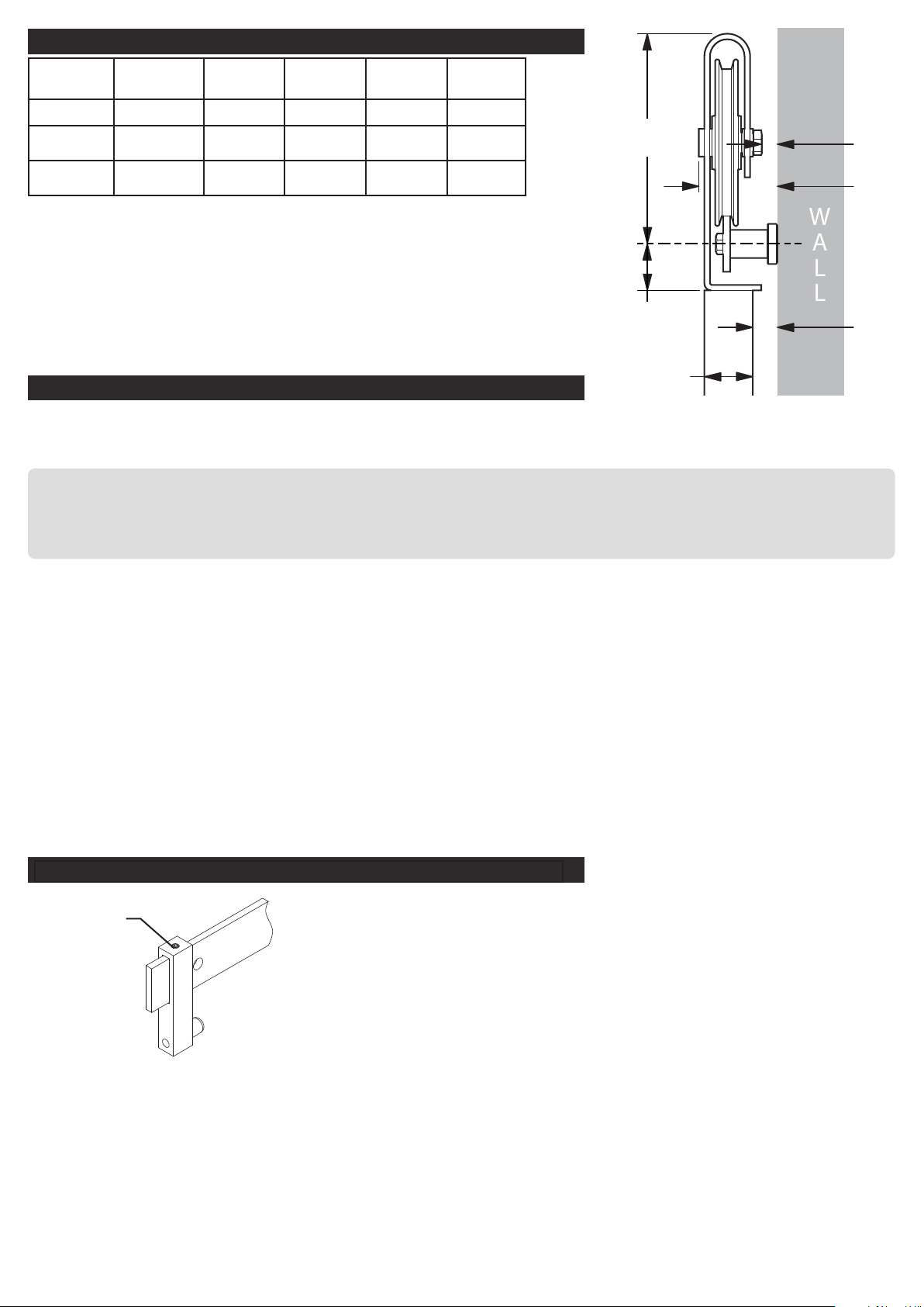
Door
Thickness
Trolley Top
to Rail
Door to
Rail Center
Bypass
Clearance
Trolley
Clearance
Door
Clearance
TD(1) (3) EW(3) X(2) Z(2)
1-3/8” 6” 1-5/16” 2-1/2”7/16”7/16”
1” 6” 1-5/16” 2-1/2”7/16”13/16”
(1)Allow at least 3/4”clearance above the trolley.
(2)The nominal distance with the door hung to run vertical and the
wall straight and plumb. Improper installation, warped doors, extra
hardware, or decorative protrusions may reduce the clearance space.
(3)Any additional rail and hardware mounted with a bypass bracket
system should allow this amount of space or more for proper operation
of this barn rail kit.
1 - Drill Holes to Mount the Rail
Planning (continued)
Front Edge
Door Front
5/16”
(Rail not shown for clarity)
IMPORTANT
The widest part of the Spacer should be placed on the wall.
Place a Lag Screw through the hole in the Rail aligning with the
outermost pilot hole on one side, through a Spacer, and drive
the Lag Screw into the pilot hole. DO NOT fully tighten Lag
Screw.
2 - Mount the Rail
Repeat process for a Lag Screw on the opposite end of Rail. DO NOT fully tighten Lag Screw.
Insert remaining Lag Screws through Rail holes and Spacers, and drive into pilot holes. DO NOT
fully tighten Lag Screws.
After all Lag Screws and Spacers are in place, use a level on top of the Rail to make sure it is
properly level. While making sure the Rail is level, tighten all Lag Screws securely.
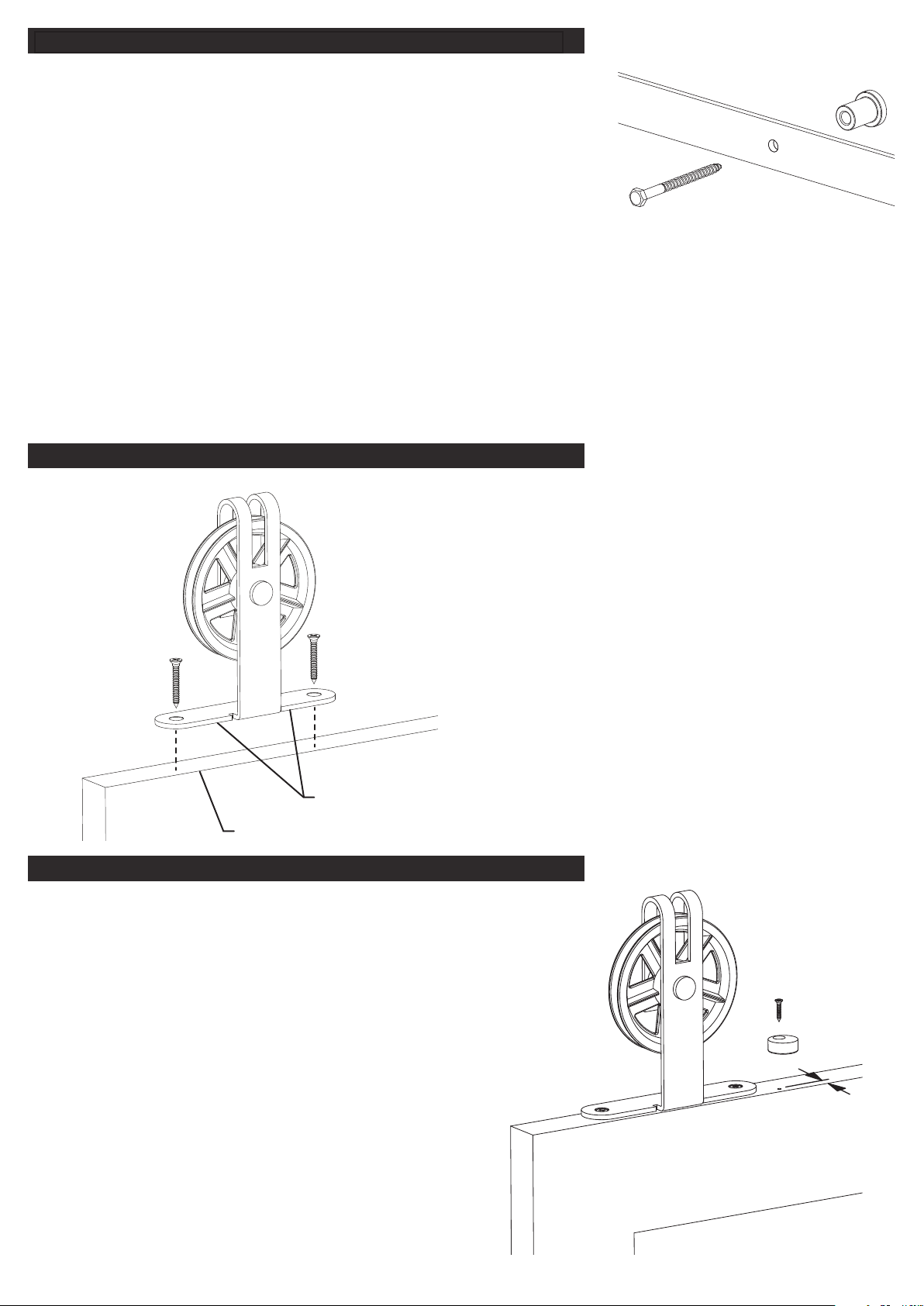
3 - Install Trolleys and Hang the Door
Place the Trolley on top of the door as shown and
mark the location of the holes for the Trolley
Screws. Align the front edge of the base ange
on each Trolley with the door front.
Drill pilot holes using a 3/32” bit and attach the
Trolleys to the door with the Trolley Screws.
Hang the door on the Rail. Make sure both rollers
are in contact with the Rail and that the door is
level.
4 - Install Anti-Jump Pads
Drill two 3/32” pilot holes in the top of the door and
located between and near the Trolleys, as shown
in the diagram, in order to mount the Anti-Jump
Pads.
Place the Anti-Jump Pads on the top of the door
and attach with the 3/4” Phillips Screws.
Make sure the Anti-Jump Pad is positioned so that
the hole is towards the front side of the door and
the body of the Pad is underneath the Rail.

(T)
plus
3/32”
(2mm)
Door
Thickness (T)
Floor
Anchor
1-1/4”
Screw
Locate the Door Guides on either side of the door, as close
to the doorway as possible. See the diagram for proper
Move the door to the desired closed position. Place a Door Stop so that the bumper contacts
the door and the set screw is facing up. Secure the Door Stop by tightening the set screw.
Move the door to the desired open position and repeat with the remaining Door Stop.
5 - Install Door Guides and Secure Door Stops
OTHER QUESTIONS?
spacing.
If the oor is not solid
wood, it may be
necessary to use
the Floor Anchors in
addition to the screws.
Drill 3/32” pilot holes if
using screws only, or
1/4” pilot holes if using
Floor Anchors.
REV-04
NEED EXTRA PARTS or OPTIONAL ACCESSORIES?
Additional parts and accessories are available exclusively at
www.menards.com/barndoorhardware
or your local Menards store, including rails, rail connectors, spacer kits,
soft-close mechanisms, bypass brackets, locks, and handles.
NOTE: If using this kit to hang an additional door on a All-In-One Barn Rail Kit,
check the All-In-One Barn Rail Kit instructions BEFORE beginning installation.
NOTE: If installing a soft-close mechanism (431-0451), check the soft-close instructions
BEFORE beginning installation.
NOTE: If installing bypass brackets (431-0446, 431-0447, 431-0452), check the bypass bracket
instructions BEFORE beginning installation.
DO NOT RETURN TO THE STOREContact Customer Care
1-800-721-4191
Monday – Friday
8 - 5 Central Time
This manual suits for next models
1
Other Forge Door Opening System manuals

Popular Door Opening System manuals by other brands


Alcad
Alcad IVANDAL instruction manual

Bohle
Bohle MasterTrack ST 90 instruction manual

GEZE
GEZE Slimdrive EMD Invers Installation and service instructions

RIB
RIB TOUCH Wi-Fi 2.0 Installation

Nitto Kohki
Nitto Kohki NSC-C23 installation manual

Besam
Besam Swingmaster MP Installation, adjustment and maintenance instructions

Synergy Hardware
Synergy Hardware S800 Series Fixing instructions

Canaropa
Canaropa 851 installation instructions

uhlmann & zacher
uhlmann & zacher Clex private CX2122 Operating and assembly manual

Dorma
Dorma CS 80 MAGNEO Technical documentation

Assa Abloy
Assa Abloy Norton 1600H manual

CAMDEN
CAMDEN CM-300 installation instructions