8
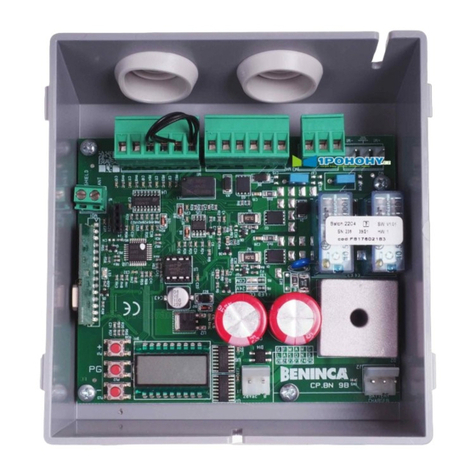
DA.2S Synchronisation card
The DA.2S interface allows to connect 2 automatic systems together (sliding doors, balancing doors, door leaves, …).
The coupling is provided by a double-exchange relay, which ensures the insulation between the two systems to be
activated.
Installation instructions.
a) The electrical installation and functioning logic must comply with current standards.
b) Keep the power cables (for the motor and power supply) away from the control cables (buttons, photocells, radio).
To avoid interference use two separate sheaths.
c) Check all the connections again before supplying voltage.
Input/Output functions
(1,2) 24VAC Interface power supply, 24VAC, 50Hz, coming from one of the two control panels to be
activated.
(3,4) + 24V Common to all interface inputs, “+24V”
(5) FOTOC Input, Normally Closed contact of the photocell receiver (see wire diagram)
(6) STOP Input, STOP push button (Normally Closed)
(7) P.P. Input, Step-by-Step push button (Normally Open)
(8,9) FOTO 1 Output, 1st Normally Closed contact of the double-exchange relay, triggered by the
FOTOC input.
To be connected to the relevant input of the “control panel 1” to be controlled
(10,11) FOTO2 Output, 2nd Normally Closed contact of the double-exchange relay, triggered by the
FOTOC input.
To be connected to the relevant input of the “control panel 2” to be controlled
(12,13) STOP1 Output, 1st Normally Closed contact of the double-exchange relay, triggered by the
STOP input.
To be connected to the relevant input of the “control panel 1” to be controlled
(14,15) STOP2 Output, 2nd Normally Closed contact of the double-exchange relay, triggered by the
STOP input.
To be connected to the relevant input of the “control panel 2” to be controlled
(16,17) PP1 Output, 1st Normally Open contact of the double-exchange relay, triggered by the P.P.
input.
To be connected to the relevant input of the “control panel 1” to be controlled
(18,19) PP1 Output, 2nd Normally Open contact of the double-exchange relay, triggered by the P.P.
input.
To be connected to the relevant input of the “control panel 2” to be controlled
(20,21) APRE1 Output, 1st Normally Open contact of the double-exchange relay, triggered by the APRE
input.
To be connected to the relevant input of the “control panel 1” to be controlled
(22,23) APRE2 Output, 2nd Normally Open contact of the double-exchange relay, triggered by the
APRE input.
To be connected to the relevant input of the “control panel 2” to be controlled
(24,25) CHIUDE1 Output, 1st Normally Open contact of the double-exchange relay, triggered by the
CHIUDE input.
To be connected to the relevant input of the “control panel 1” to be controlled
(26,27) CHIUDE2 Output, 2nd Normally Open contact of the double-exchange relay, triggered by the
CHIUDE input.
To be connected to the relevant input of the “control panel 2” to be controlled
(28) APRE Input, APRE push button (Normally Open)
(29) CHIUDE Input, CHIUDE push button (Normally Open)

