manuals.online logo
Brands
  1. Home
  2. •
  3. Brands
  4. •
  5. Bohle
  6. •
  7. Door Opening System
  8. •
  9. Bohle Verifix 638.0 User manual

Bohle Verifix 638.0 User manual

Einsatzbereich
Verifix®Winkelpumpensauger Art.-Nr. 638.0
Die Verifix Winkelpumpensauger werden hauptsächlich bei der Glas-
verklebung mit niederviskosen UV-Klebstoffen eingesetzt. Hier eignen
sie sich sehr gut, um kleinere Glasscheiben bis zu einer Höhe von ca.
60 cm in einem rechten Winkel zueinander zu positionieren. Jeder
Verifix®Winkelpumpensauger verfügt über zwei eingebaute Vakuum-
pumpen, die über Ventile einzeln belüftet werden können. Ein roter
Kontrollring zeigt Vakuumverlust an; durch kurzes Nachpumpen kann
die Verbindung wieder gefestigt werden.
Verifix®Winkelpumpensauger-Set, Art.-Nr. 638.9
Da diese Fixierhilfen in der Praxis fast immer paarweise eingesetzt
werden, bieten wir ein entsprechendes Set im stabilen Transportkoffer
an. So sind Ihre wertvollen Geräte immer gut geschützt.
Sicherheitshinweise
Prüfen Sie die Saugflächen vor jeder Anwendung. Sie sollten glatt,
sauber und unbeschädigt sein. Der umlaufende Gummiring darf
keine Risse aufweisen.
Prüfen Sie, ob die/der anzusaugende Fläche/Gegenstand aus gas-
dichtem Material besteht. Darüber hinaus muss diese Fläche
sauber, trocken und frei von Ölen und Fetten sein. Auf rauhen und
porösen Oberflächen verringert sich die Haltekraft bzw. ist nicht
vorhanden.
Die Erzeugung des Vakuums muss deutlich spürbar sein, der rote
Kontrollring darf nicht sichtbar sein. Der Sauger ist nur zum
kurzfristigen Halten geeignet.
Lösen Sie den Winkelpumpensauger erst dann, wenn der Gegen-
stand gesichert oder die Verklebung fest ist.
Benutzen Sie keine spitzen Gegenstände, um den Winkelpumpen-
sauger vom Untergrund zu lösen.
Achtung! Wichtiger Hinweis
Die dargestellten Anwendungen sind Beispiele und berücksichtigen
nicht die besonderen Umstände im Einzelfall des Anwenders. Daher
liegt es in der Verantwortung des Anwenders, die Eignung für den
beabsichtigten Verwendungszweck zu prüfen. Insoweit ist unsere Haf-
tung ausgeschlossen, insbesondere für Folge- oder Vermögensschäden.
Technische Änderungen an den Produkten sowie Änderungen der tech-
nischen Daten in dieser Bedienungsanleitung sind vorbehalten.
Anwendung
1Fixieren Sie den Winkelpumpensauger auf der ersten Scheibe
durch Betätigen des unteren Pumpstößels.
2Der Winkelpumpensauger saugt sich an das Glas an und hat nun
die richtige Ausgangsposition. Fixieren Sie nun die zweite Scheibe,
indem Sie sie gegen den Sauger drücken und den oberen
Pumpstößel betätigen.
3Lösen Sie nun durch Betätigen des oberen Belüftungsventils
den unteren Sauger, heben Sie den Sauger mit der angesaugten
zweiten Glasscheibe zusammen an und positionieren Sie diese an
der gewünschten Stelle.
4Fixieren Sie den Sauger wieder durch Betätigen des unteren
Pumpstößels.
Wartung und Pflege
Verwenden Sie zum regelmäßigen Reinigen der Saugflächen und
der Dichtgummis nur Bohle Spezialreiniger oder ähnliche nicht
agressive Reinigungsmittel.
Achten Sie darauf, dass die Saugflächen (Punkt A) nicht
beschädigt oder verkratzt werden.
Lagern Sie den Winkelpumpensauger nur in gezeigter Position (5)
oder im original Transportkoffer.
Folgende Ersatzteile sind erhältlich:
SP B0187 Dichtring
SP B0881 kleine Vakuumpumpe
Austausch des Dichtrings:
Nehmen Sie den alten Dichtring heraus. Reinigen Sie den neuen Dich-
tring und, wenn nötig, die Rille, in die er eingesetzt wird, mit Glasreini-
ger. Drücken Sie den neuen Dichtring in die Rille. Prüfen Sie danach die
Position, in dem Sie zwei Scheiben zueinander fixieren und den Winkel
prüfen. Liegen keine 90° an, kann die Position des Dichtrings durch dar-
überstreichen verändert werden, bis der Winkel exakt 90° ist.
Austausch der Vakuumpumpe
Lösen Sie die Schrauben, um den Winkelpumpensauger zu demon-
tieren.Tauschen Sie die Vakuumpumpe. Ersetzten Sie dabei die alten
Dichtringe und den O-Ring durch die neuen beiliegenden Dichtungen.
Dadurch wird sicher gestellt, dass die Vakuumpumpe nach dem Aus-
tausch wieder dicht ist und ein Vakuum hergestellt werden kann.
51234
BO 638.0 Bedienungsanleitung / Operating Instructions / Instructions de commande
Fields of application
Verifix®Pump-activated angle suction holder,
art. no. 638.0
The Verifix®pump-activated angle suction holders are mainly used
together with low-viscosity UV adhesives. They are very well suited for
positioning smaller glass panes with a maximum height of 60 cm in a
90° angle to each other. Each Verifix® pump-activated angle suction
holder is equipped with two integrated vacuum pumps which can be
ventilated individually via valves. A red contol ring indicates a possible
loss of vacuum; the holding power can be restored by briefly engaging
the pump.
Verifix®Pump-activated angle suction holder set,
art. no. 638.9
As these fixing aids are in practice nearly always used in pairs, we
offer them as a set, packed in a sturdy carrying case, which offers
permanent protection to your valuable tools.
Safety Instructions
Check the suction surface each time it is used. It should be smooth
and clean and show no signs of damage. The rubber ring must be
free from cracks.
Ensure that the surface or object to be handled is made of airtight
material. This surface should also be clean and dry and free of oil
or grease. Suction power diminishes or disappears altogether on
rough or porous surfaces.
Vacuum production must be clearly noticeable, the red control ring
must not be visible. The suction device is designed for use during
short periods only.
Do not release the pump-activated angle suction holder until the
object it is holding is secured, or the adhesive has fully cured.
Do not use sharp or pointed objects to remove the angle
suction lifter from the surface it is attached to.
Caution! Important Note
The uses mentioned are examples and do not refer to the special
individual circumstances of each user. The user is thus responsible for
ensuring that the tool is suitable for his/her individual requirements.
We accept no liability for any consequences or damage resulting from
improper use. We reserve the right to carry out both technical
modifications to our products and amendments to the technical data
shown in these instructions.
Instructions for use
1Fix the pump-activated angle suction holder on the first glass pane
using the lower pump tappet.
2 The suction holder becomes attached to the glass through the force
of the vacuum and now has the correct position. Now fix the
second pane by pressing it against the suction pad while activating
the upper pump tappet.
3 Then loosen the inferior suction pad by opening the upper venting
valve, lift the suction holder together with the attached second
glass pane and place it in the desired position.
4 Fix the suction holder again by activating the lower pump tappet.
Care and maintenance
Use Bohle Special Cleaner or similar non-aggressive cleaners only
for the regular cleaning of suction pads or rubber gaskets.
Ensure that the suction surfaces (Item A) are not damaged or
scratched.
Store the pump-activated angle suction holder only in the position
shown (5) or in its original carrying case.
The following spare parts are available:
SP B0187 Sealing ring
SP B0881 Small vacuum pump
Exchange of the sealing ring:
Remove the old sealing ring. Clean the new sealing ring and, if
required, the groove which it is introduced into with glass cleaner.
Afterwards check for correct positioning by fixing two glass panes
and checking whether they are positioned in an exact 90° angle. If the
angle is not exactly 90°, the position of the sealing ring can be
changed by moving one finger across it until the angle reaches exactly
90°.
Exchange of the vacuum pump:
Loosen the screws for disassembling the angle suction holder.
Exchange the vacuum pump. When doing so, replace the old sealing
rings and the O-ring by the supplied gaskets. In this way you make sure
that the vacuum pump is completely tight after exchanging it and the
vacuum can be generated without difficulty.
Domaine d’utilisation
Ventouse à pompe coudée Verifix®, Réf. 638.0
Les ventouses Verifix sont utilisées surtout pendant le collage du verre
avec des colles UV à faible viscosité. Elles conviennent parfaitement
pour positionner des verres à angle droit, d'une hauteur max. d'environ
60 cm. Chaque ventouse à pompe coudée Verifix®est dotée de deux
pompes à vide intégrées et actionnables
séparément pour permettre de corriger les positions de montage. Une
bague de contrôle rouge indique la perte de vide. La liaison pourra être
rétablie par simple pompage.
Set de ventouses à pompe coudées Verifix®, Réf. 638.9
Comme ces accessoires de fixation sont quasiment toujours utilisés
deux par deux, nous proposons l’ensemble adéquat dans une mallette
spéciale (5). Vos précieux appareils seront donc bien protégés.
Informations de sécurité
Contrôler la surface d’aspiration avant chaque utilisation. Elle doit
être lisse, propre, intacte et ne présenter aucune fissure. Le joint
en caoutchouc ne doit présenter aucune fissure.
Contrôler si la surface/l’élément sur laquelle/lequel la ventouse est
appliquée est étanche aux gaz. Cette surface doit en outre être
propre, sèche et exempte d’huile et de graisse. Les surfaces
poreuses et rugueuses réduisent ou rendent impossible toute
aspiration.
La création du vide doit être clairment perceptible, la bague de
contrôle rouge ne doit pas être visible. La ventouse est uniquement
prévue pour le maintien de courte durée des verres.
Relâcher la ventouse à pompe coudée seulement lorsque l’objet
est solidement maintenu en place ou après la prise de la colle.
Ne pas utiliser d’objets pointus pour relâcher la ventouse.
Attention ! Important !
Les consignes citées ci-avant ne sont que quelques exemples et ne
tiennent pas compte des données particulières de l’utilisateur. Il appar-
tient à l’utilisateur de s’assurer de l’adéquation entre son contexte et
les applications de l’équipement. Dans ce cadre, nous excluons toute
responsabilité, notamment en ce qui concerne les dommages
consécutifs et matériels. Sous réserve de modification des caracté-
ristiques techniques contenues dans le présent mode d’emploi.
Instructions d'utilisation
1 Fixez la ventouse à pompe coudée sur le premier verre en
actionnant le piston du bas.
2 La ventouse est aspirée contre le verre et a maintenant la bonne
position de départ. Fixez maintenant le deuxième verre en
l'appuyant contre la ventouse et en actionnant le deuxième piston.
3 En actionnant la soupape du haut, détachez le verre du bas,
soulevez la ventouse avec le second verre attaché et positionnez
celui-ci à la position désirée.
4 Refixez la ventouse en actionnant le piston du bas.
Maintenance et entretien
Pour le nettoyage régulier de la surface de succion et des caout
choucs d'étanchéité, utilisez uniquement le produit de nettoyage
spécial Bohle ou un produit de nettoyage semblable non aggressif.
Veiller à ne pas endommager et rayer les surfaces d’aspiration
(point A).
Entreposer la ventouse à pompe coudée uniquement dans la
position illustrée (5) ou dans sa mallette d’origine.
Pièces détachées en vente :
SP B0187 Joint détanchéité
SP B0881 Petite pompe à vide
Remplacement du joint d'étanchéité :
Ôter l'ancien joint d'étanchéité. Nettoyez le nouveau joint et, si néces-
saire, la rainure dans laquelle le joint sera placée, en utilisant du
nettoyant pour verre. Enfoncez le nouveau joint dans la rainure. Vérifiez
ensuite la position en fixant 2 verres, vérifiez l'angle. Si l'angle n'est
pas de 90°, la position du joint peut être modifiée en glissant par des-
sus avec le doigt jusqu'à ce que l'angle de 90° soit atteint.
Remplacement de la pompe :
Desserrez les vis afin de démonter la ventouse coudée. Remplacez la
pompe. Remplacez en même temps les anciens joints d'étanchéité et
l'anneau O par les joints livrés avec la pompe. Ainsi, vous êtes sûr que
la pompe soit à nouveau étanche après le remplacement.
Bohle AG · Dieselstraße 10 · 42781 Haan · T +49 2129 5568-0 · F +49 2129 5568-281 · www.bohle-group.com · [email protected]
Campos de aplicación
Ventosa angular de pistón Verifix®, ref. 638.0
Las ventosas angulares de pistón Verifix®están concebidas sobre todo
para uso con adhesivos UV de baja viscosidad. Son especialmente
apropiadas para posicionar vidrios de tamaño pequeño hasta una
altura de 60 cm en un ángulo de 90°. Cada ventosa angular de pistón
Verifix® dispone de dos bombas de vacío integradas que se pueden
ventilar individualmente mediante válvulas. Un anillo rojo indica una
posible pérdida de vacío; la fuerza de agarre se puede restablecer al
brevemente accionar la bomba.
Juego de ventosas angulares de pistón Verifix®, ref. 638.9
Dado que en la práctica estos dispositivos de fijación se emplean casi
siempre de dos en dos en dos, le ofrecemos un juego correspondiente
presentado en un maletín estable de transporte. De esa manera, su
valioso equipo estará siempre bien protegido.
Avisos de Seguridad
Compruebe las superficies de la ventosa antes de cada empleo.
Las mismas deberían estar lisas, impecables y sin daños.
El anillo de goma sin no debe presentar grietas.
Compruebe que la/el superficie/objeto en el/la que se va a aplicar
la ventosa se componga de materiales herméticos. Además esta
superficie debe estar limpia, seca y exenta de aceites y grasas. En
superficies rugosas y porosas la fuerza de sujeción se reduce o
desaparece por completo.
La formación de vacío tiene que percibirse con claridad, el anillo de
control rojo no debe ser visible. La ventosa sólo está concebida
para una fijación de corta duración.
Suelte la ventosa angular de pistón únicamente después de que
el objeto se haya asegurado o el adhesivo se haya secado
completamente.
No utilice objetos agudos para desprender la ventosa angular de
pistón de la superficie en la que está fijada.
¡Atención! Aviso importante
Las aplicaciones presentadas son ejemplos y no tienen en cuenta las
circunstancias especiales que se pueden presentar en el caso indivi-
dualizado del usuario. Por este motivo es responsabilidad del usuario
verificar la aptitud de la herramienta para el uso previsto.
De tal modo, Bohle queda exonerado de cualquier responsabilidad,
especialmente en lo que a daños consecuenciales o patrimoniales se
refiere.
Queda reservado el derecho a modificaciones técnicas en los produc-
tos, así como, modificaciones de los datos técnicos en las presentes
instrucciones de uso.
Instrucciones de uso
1Fije la ventosa angular en el primer vidrio accionando el pistón
inferior, de tal modo tiene la posición correcta.
2 Ahora fije el segundo vidrio presionándolo contra la ventosa y
accionando el pistón superior.
3 Después suelte la ventosa inferior mediante la válvula superior,
levante la ventosa junto con el segundo vidrio pegado y colóquelo
en la posición deseada.
4 Vuelva a fijar la ventosa accionando el pistón inferior.
Mantenimiento y cuidado
Para la limpieza periódica de las superficies de las ventosas y
gomas sellantes, utilice solamente el Limpiador Especial Bohle o
limpiadores similares no agresivos.
Procure que las superficies de goma (Punto A) estén libres de
daños y rasguños.
Guarde la ventosa angular de pistón sólo en la posición (5) que se
muestra o en el maletín de transporte original.
Están disponibles las siguientes piezas de repuesto:
SP B0187 Anillo sellador
SP B0881 Bomba de vacío pequeña
Intercambiar el anillo sellador:
Quite el viejo anillo sellador. Límpie el nuevo anillo y, si hace falta,
también la ranura en la que se va a insertar con limpiador de vidrio.
Insierte el nuevo anillo sellador en la ranura. A continuación, comprue-
be el posicionamiento correcto al fijar dos vidrios y verificar si el ángu-
lo está exactamente en 90°. Si no está en 90°, la posición del anillo
sellador se puede cambiar frotándolo con un dedo hasta que el ángulo
llegue exactamente a 90°.
Intercambiar la bomba de vacío:
Suelte los tornillos para desmontar la ventosa angular de pistón. Inter-
cambie la bomba de vacío y reemplace los anillos selladores y el anillo
tórico por los nuevos sellos suministrados. De tal modo asegura de que
la bomba de vacío quede totalmente hermética y que el vacío se pueda
generar sin problemas.
BO 638.0 Instrucciones de uso / Istruzioni d’ uso / Gebruiksaanwijzing
Campi di applicazione
Ventosa a pompa angolare Verifix®, Art.-no. 638.0
Le ventose a pompa angolari Verifix® sono principalmente utilizzate
insieme ad adesivi UV a bassa viscosità. Esse sono adatte per il posizi-
onamento di vetri medio piccoli con una altezza massima di 60 cm con
un angolo di 90 ° tra loro. Ogni ventosa a pompa angolare Verifix® è
dotata di due pompe per vuoto integrate che possono essere scaricate
singolarmente tramite valvole. Un anello di controllo rosso indica una
possibile perdita di vuoto; il potere di tenuta può essere ripristinato
impegnando brevemente la pompa.
Set ventose a pompa angolare Verifix®, Art.-no. 638.9
Poiché questi supporti di fissaggio vengono utilizzati in pratica quasi
sempre in coppia, offriamo un set con una valigia di trasporto.
In questo modo i Vostri preziosi attrezzi sono sempre ben custoditi.
Istruzioni di sicurezza
Verificate le superfici degli oggetti da fissare prima di ogni utilizzo.
Queste devono essere lisce, pulite e non danneggiate. L’anello di
gomma delle ventose non deve avere tagli.
Verificate che le superfici degli oggetti da fissare siano gas
impermeabili, pulite e prive di grasso oppure olio. Se le superfici
sono ruvide o porose diminuisce la forza di tenuta.
La creazione di vuoto deve essere accertata chiaramente, l’anello
di controllo rosso non deve essere visibile. La tenuta del vuoto è
assicurata solo per un breve periodo.
Rilasciare il vuoto solo a preincollaggio avvenuto
Non utilizzate oggetti appuntiti per allentare la ventosa a pompa
angolare dalla base.
Attenzione! Informazione importante
Gli usi suddetti sono esempi e non tengono conto di particolari condizi-
oni particolari dell’utente: Pertanto è responsabilità dell’utente esami-
nare i requisiti per lo scopo perseguito. La nostra responsabilità
è pertanto esclusa, in particolare per i danni successivi o patrimoniali.
Ci si riserva la possibilità di effettuare modifiche tecniche ai prodotti e
modifiche dei dati tecnici di queste istruzioni per l’uso.
Istruzioni per l'uso
1Fissare la ventosa a pompa sulla prima lastra di vetro
usando la pompa inferiore.
2 Il supporto a ventosa resta attaccato al vetro grazie alla forza
creata dal vuoto ed ora si trova nella posizione corretta. Fissare
quindi la seconda lastra premendola contro la ventosa attivando
nel frattempo la pompa superiore.
3 Allentare quindi la ventosa inferiore aprendo la valvola di sfiato
superiore, sollevare il supporto a ventosa insieme alla seconda
lastra di vetro che è attaccata e collocarlanella posizione
desiderata.
4 Fissare nuovamente il supporto a ventosa attivando la pompa
inferiore.
Manutenzione e cura
Per la pulizia regolare delle super fici e delle guarnizio
ni di gomma, utilizzate soltanto detergente Bohle o sostanze simili
non aggressive.
Fate attenzione che le superfici da aspirare (punto A) non vengano
danneggiate o graffiate.
Conservate la ventosa a pompa angolare solo nella posizione
mostrata (5) o nella valigetta da trasporto originale.
Sono disponibili i seguenti ricambi:
SP B0187 Anello in gomma
SP B0881 Pompa vuoto
Sostituzione dell'anello di tenuta:
Togliere la vecchia guarnizione. Pulire il nuovo anello di tenuta e, se
necessario, la scanalatura con detergente per vetri. Successivamente
controllare il posizionamento corretto fissando due lastre di vetro e
verificare se sono posizionate con un angolo di 90° perfetto.
Sostituzione della pompa a vuoto:
Allentare le viti per smontare la ventosa ad angolo. Sostituire la pompa
del vuoto. Nel fare ciò, sostituire i vecchi anelli di tenuta e l'O-ring per
le guarnizioni in dotazione. In questo modo si è sicuri che la pompa del
vuoto sia completamente a tenuta dopo la sostituzione e il vuoto possa
essere generato senza difficoltà
Inzetgebied
Verifix®haakse pompzuiger,art.-nr. 638.0
De Verifix hoek pompzuigers worden voornamelijk bij glasverlijming
met laag viscose UV- lijm gebruikt. Ze zijn in het bijzonder geschikt om
kleinere glasplaten met een hoogte tot ca. 60 cm onder een rechte
hoek tegen over elkaar te positioneren. Iedere VERIFIX hoek pompzu-
iger is voorzien van twee ingebouwde vacuümpompen, deze kunnen via
aparte ventielen los van elkaar gelost worden. Een rode
controle ring duidt vacuüm verlies aan; door kort napompen kan de
verbinding weer hersteld worden.
Verifix®haakse pompzuiger-set, art.-nr. 638.9
Omdat deze fixeerhulpen in de praktijk bijna altijd paarsgewijs ingezet
worden, bieden wij een passende set in een stabiele transportkoffer (3)
aan. Zo zijn uw waardevolle apparaten altijd goed beschermd.
Veiligheidsinstructies
Controleert u de zuigvlakken voor ieder gebruik. Zij moeten glad,
zuiver en onbeschadigd zijn. De rondom lopende gummiring mag
geen scheuren vertonen.
Controleert u of het aan te zuigen vlak / voorwerp uit gasdicht
materiaal bestaat. Bovendien moet dit vlak zuiver, droog en vrij van
olie en vet zijn. Op ruwe en poreuze oppervlakken neemt de grip af
resp. is niet aanwezig.
De aanwezigheid van het vacuüm moet duidelijk voelbaar zijn, de
rode controlering mag niet zichtbaar zijn. De zuiger is alleen voor
kortstondige fixatie geschikt.
Haalt u de haakse pompzuiger pas los, wanneer het voorwerp
beveiligd is of de verlijming vast is.
Gebruikt u geen spitse voorwerpen om de haakse pompzuiger van
de ondergrond los te halen.
Opgelet! Belangrijke aanwijzing
De afgebeelde toepassingen zijn voorbeelden en houden geen rekening
met bijzondere gebruikersomstandigheden. Daarom ligt het in de ver-
antwoordelijkheid van de toepasser, de deugdelijkheid van het
beoogde toepassingsdoel te controleren. In zoverre voor is onze aan-
sprakelijkheid uitgesloten, met name voor gevolg- en financiële scha-
de. Technische veranderingen aan de producten evenals veranderingen
van de technische gegevens in deze
Toepassing
1 Fixeer de hoek pompzuiger op de eerste glasplaat door het
meermaals indrukken van de onderste pomp.
2 De hoek pompzuiger zuigt zich aan het glas vast en heeft nu de
juiste uitgangspositie.
Fixeer nu de tweede glasplaat, door deze tegen de zuiger te
drukken en de bovenste pomp meermaals in te drukken.
3 Los nu door het indrukken van het bovenste ontluchtingsventiel de
onderste zuiger,til de zuiger samen met de aangezogen glasplaat
op en plaats deze op de gewenste positie.
4 Fixeer nu de zuiger weer door het meermaals indrukken van de
onderste pomp.
Onderhoud
Gebruik voor de regelmatige reiniging van de zuigvlakken en de
rubber dichtring alleen Bohle speciaal reiniger of een soortgelijk
niet agressief reinigingsmiddel
Let u erop, dat de zuigvlakken (punt A) niet beschadigd of bekrast
raken.
Bewaart u de haakse pompzuiger alleen in de getoonde positie (3)
of in de originele transportkoffer.
De volgende onderdelen zijn verkrijgbaar:
SP B0187 rubber dichtring
SP B0881 kleine vacuümpomp
Vervangen van de afdichtring:
Verwijder de oude dichtring. Reinig de nieuwe dichtring.
En, indien nodig, de uitsparing waar deze ingezet wordt met glasrei-
niger. Druk de nieuwe dichtring in de uitsparing. Controleer daarna
de positie, door twee glasplaten aan elkaar te fixeren en de hoek te
controleren. Is deze geen 90° dan kan de positie van de dichtring door
erover te wrijven veranderd worden, tot de hoek exact 90° is.
Vervangen van de vacuümpomp
Draai de schroeven los om de zuiger te demonteren.
Vervang de vacuümpomp. Vervang daarbij ook de oude dichtringen en
de O- ring door de nieuwe meegeleverde dichtingen.
Hierdoor wordt zeker gesteld dat de vacuümpomp na het vervangen
weer dicht is en het vacuüm weer opgebouwd kan worden.
51234
Bohle AG · Dieselstraße 10 · 42781 Haan · T +49 2129 5568-0 · F +49 2129 5568-281 · www.bohle-group.com · [email protected]
BT0638 · 2015-5205 · 1,0

Other Bohle Door Opening System manuals

Bohle BO 5215430H User manual

Bohle

Bohle BO 5215430H User manual

Bohle Madrid User manual

Bohle

Bohle Madrid User manual

Bohle BO 5215496 User manual

Bohle

Bohle BO 5215496 User manual

Bohle Juna User manual

Bohle

Bohle Juna User manual

Bohle MasterTrack BT Teleskop 3 User manual

Bohle

Bohle MasterTrack BT Teleskop 3 User manual

Bohle BO 5215434 User manual

Bohle

Bohle BO 5215434 User manual

Bohle MasterTrack BT User manual

Bohle

Bohle MasterTrack BT User manual

Bohle Corner Clamp adjustable Flush User manual

Bohle

Bohle Corner Clamp adjustable Flush User manual

Bohle BO 5215433 User manual

Bohle

Bohle BO 5215433 User manual

Bohle MasterTrack FT User manual

Bohle

Bohle MasterTrack FT User manual

Bohle BO 5215493 User manual

Bohle

Bohle BO 5215493 User manual

Bohle MasterTrack BT User manual

Bohle

Bohle MasterTrack BT User manual

Bohle SmartClose User manual

Bohle

Bohle SmartClose User manual

Bohle MasterTrack ST 90 User manual

Bohle

Bohle MasterTrack ST 90 User manual

Bohle Santos User manual

Bohle

Bohle Santos User manual

Bohle BO 51 015 71/2 User manual

Bohle

Bohle BO 51 015 71/2 User manual

Bohle MasterTrack BT User manual

Bohle

Bohle MasterTrack BT User manual

Bohle SmartStop GLASS User manual

Bohle

Bohle SmartStop GLASS User manual

Bohle BO 5101551N User manual

Bohle

Bohle BO 5101551N User manual

Popular Door Opening System manuals by other brands

Dorma COMFORTDRIVE Moveo Original Operating Instruction Manual

Dorma

Dorma COMFORTDRIVE Moveo Original Operating Instruction Manual

CNC Solutions DOOR MATE manual

CNC Solutions

CNC Solutions DOOR MATE manual

Lamp HC-30L installation manual

Lamp

Lamp HC-30L installation manual

GU DTN 80 operating instructions

GU

GU DTN 80 operating instructions

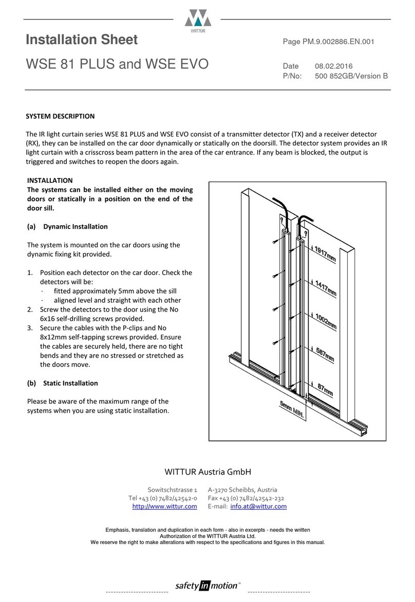
WITTUR WSE 81 PLUS Series Installation sheet

WITTUR

WITTUR WSE 81 PLUS Series Installation sheet

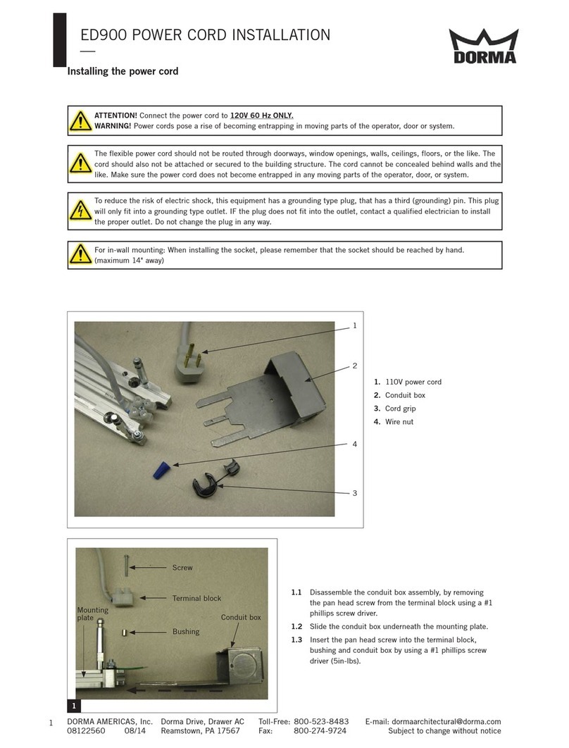
Dorma ED900 quick start guide

Dorma

Dorma ED900 quick start guide

LCN ELECTRIC AUTO-EQUALIZER 4630 manual

LCN

LCN ELECTRIC AUTO-EQUALIZER 4630 manual

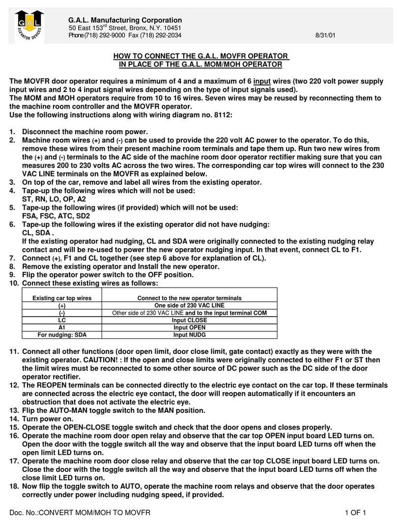
GAL MOM How to connect

GAL

GAL MOM How to connect

ENFORCER SD-961A-36GQ installation manual

ENFORCER

ENFORCER SD-961A-36GQ installation manual

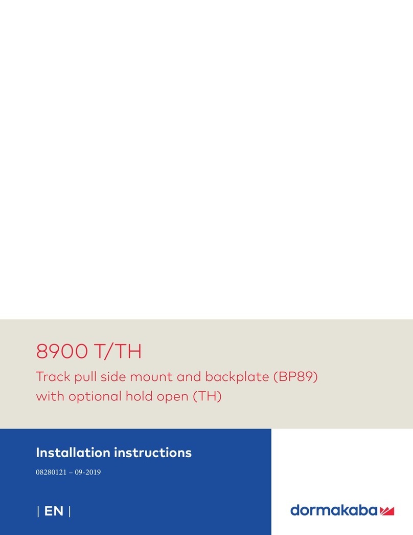
Dormakaba 8900 T installation instructions

Dormakaba

Dormakaba 8900 T installation instructions

eSSL C3-400 user manual

eSSL

eSSL C3-400 user manual

4Ddoors 4DR1 v4 Installation instructions and owner's manual

4Ddoors

4Ddoors 4DR1 v4 Installation instructions and owner's manual

cinetto PS10 Assembly instructions

cinetto

cinetto PS10 Assembly instructions

Assa Abloy Norton 8000 Series installation instructions

Assa Abloy

Assa Abloy Norton 8000 Series installation instructions

Brookfield Industries NB-500 manual

Brookfield Industries

Brookfield Industries NB-500 manual

SDC EP493 installation instructions

SDC

SDC EP493 installation instructions

G-U BKS SecureConnect 200 Mounting and operation instructions

G-U

G-U BKS SecureConnect 200 Mounting and operation instructions

Dormakaba ED100 installation instructions

Dormakaba

Dormakaba ED100 installation instructions

manuals.online logo
manuals.online logoBrands
  • About & Mission
  • Contact us
  • Privacy Policy
  • Terms and Conditions

Copyright 2025 Manuals.Online. All Rights Reserved.