Forma Scientific 310 Series Operating instructions

Forma Scientific, Inc.
*Refer to listing of models on Page iii.
Millcreek Road, P.O. Box 649
Marietta, Ohio 45750
U.S.A.
Telephone: (740) 373-4763
Telefax: (740) 373-4189
______________________________________
Model: 310 Series*
Direct Heat
CO2Incubator
Operating and Maintenance
Manual
Manual No: 7000310 Rev. 4
Read this Instruction Manual
Failure to read, understand and follow the instructions in this manual may result in damage to the
unit, injury to operating personnel and poor equipment performance.
CAUTION! All internal adjustments and
maintenance must be performed
by qualified service personnel.
Refer to the serial tag on the
rear cover of this manual

FormaModel 310 Series _________________________________________________
ii
The material in this manual is for information purposes only. The contents and the
product it describes are subject to change without notice. Forma Scientific, Inc. makes no
representations or warranties with respect to this manual. In no event shall Forma Scientific,
Inc. be held liable for any damages, direct or incidental, arising out of or related to the use
of this manual.
Manual No. 7000310
4 18943/IN-2794 3/8/00 Updated 310-203 drawing, mounting hdwe & tubing – cntrl panel ccs
-- 18766/IN-2766 12/13/99 Removed RH SNSR ERR alarm ccs
3 18675/IN-2755
18552/IN-2739
11/10/99 Updated illustated parts lists
Blower motor seal change to 730068 & 730069
ccs
-- 18457/IN-2721 8/13/99 Updated 310-203 for parts list change ccp
-- 18390/IN-2714 7/6/99 Updated elect. parts drawing -added outlet label P/N 220259 ccp
2 18117/IN-2701 5/25/99 Updated vinyl push rivets to nylon screws in door reverse ccp
1 18121/IN-2678 3/8/99 Added cord p/n, decl. of conf. for copper, updated parts list ccp
-- IN-2668 2/10/99 Parts list addition deg
0 11/98 Original manual ccp
REV ECR/ECN DATE DESCRIPTION By
FormaModel 310 Series _________________________________________________
iii
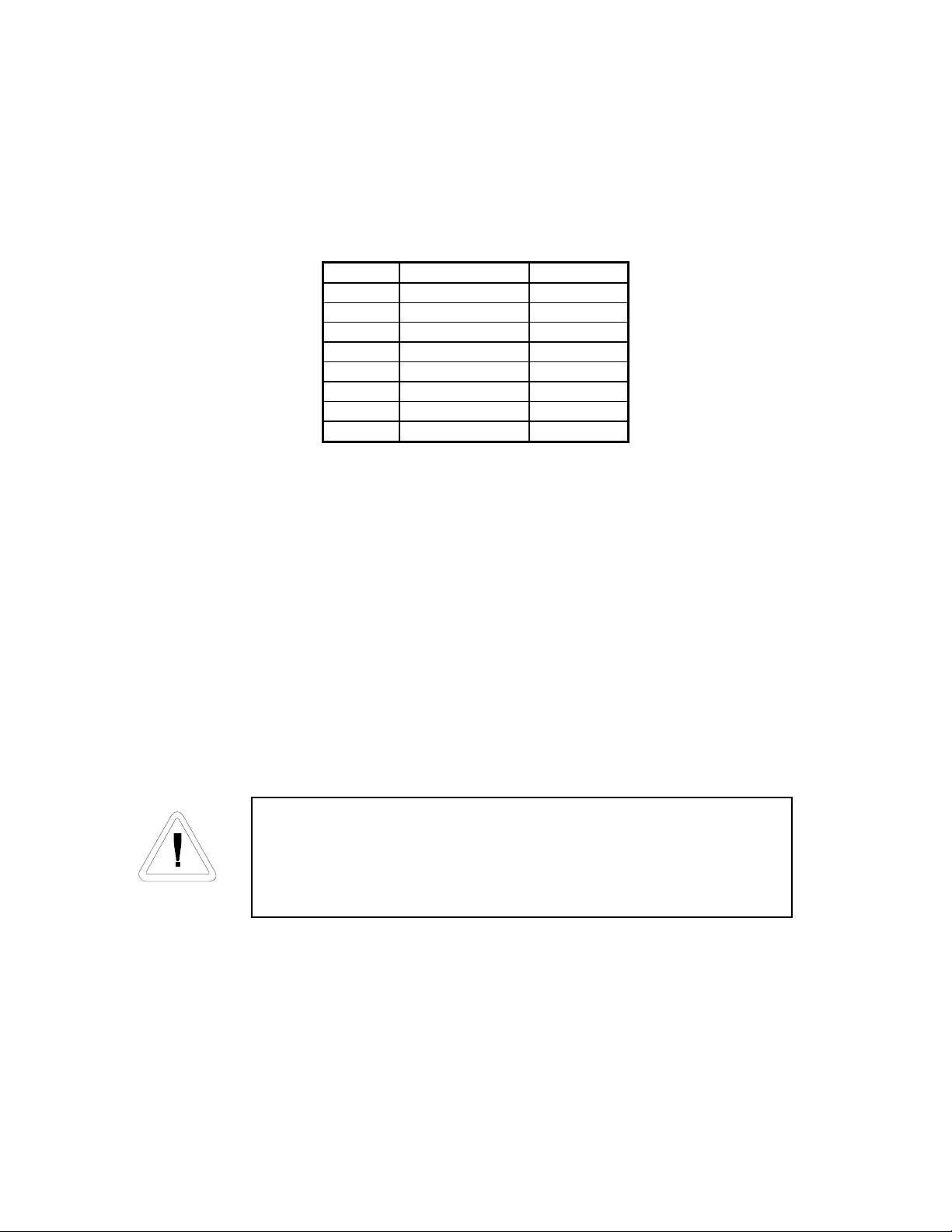
Model CO2 Sensor* Voltage**
310 T/C 115
311 T/C 230
320 IR 115
321 IR 230
350 T/C 115
351 T/C 230
360 IR 115
361 IR 230
*T/C is a thermal conductivity sensor. IR is an infrared sensor.
**All units are 50/60 HZ
If the incubator is not used in the manner specified in this
operating manual, the protection provided by the equipment
design may be impaired.

FormaModel 310 Series _________________________________________________
iv
General Safety Notes used in this Manual
Important operating and/or maintenance instructions. Read the accompanying text
carefully.
Ce symbole attire l’attention de l’utilisateur sur des instructions importantes de
fonctionnement et/ou d’entretien. Il peut être utilisé seul ou avec d’autres symboles de
sécurité. Lire attentivement le texte d’accompagnement.
Wichtige Betriebs- und/oder Wartungshinweise. Lesen Sie den nachfolgenden Text
sorgfältig.
Importante instruccions de operacion y/o mantenimiento. Lea el texto acompanante
cuidadosamente.
Potential electrical hazards. Only qualified persons should perform procedures
associated with this symbol.
Ce symbole attire l’attention de l’utilisateur sur des risques électriques potentiels.
Seules des personnes qualifiées doivent appliquer les instructions et les procédures
associées à ce symbole.
Gefahr von Stromschlägen. Nur qualifizierte Personen sollten die Tätigkeiten
ausführen, die mit diesem Symbol bezeichnet sind.
Potencial de riesgos electricos. Solo personas das capacitadadas deben ejecutar los
procedimientos asociadas con este simbulo.
√Always use the proper protective equipment (clothing, gloves, goggles etc.).
√Always dissipate extreme cold or heat and wear protective clothing.
√Always follow good hygiene practices.
√Each individual is responsible for his or her own safety.

FormaModel 310 Series _________________________________________________
v
Do You Need Information or Assistance on Forma
Products?
do, please contact us 8:00 a.m. to 7:00 p.m. (Eastern Time) at:
1-740-373-4763 Direct
1-888-213-1790 Toll Free, U.S. and Canada
1-740-373-4189 FAX
http://www.forma.com Internet Worldwide Web Home Page
fservice@forma.com Service E-Mail Address
If you
Our staff can provide information on pricing and give you quotations. We
can take your order and provide delivery information on major equipment items or make
arrangements to have your local sales representative contact you. Our products are listed on the
Internet and we can be contacted through our Internet home page.
Our staff can supply technical information about proper setup,
operation or troubleshooting of your equipment. We can fill your needs for spare or replacement
parts or provide you with on-site service. We can also provide you with a quotation on our
Extended Warranty for your Forma products.
Whatever Forma products you need or use, we will be happy to discuss your
applications. If you are experiencing technical problems, working together, we will help you
locate the problem and, chances are, correct it yourself...over the telephone without a service
call.
When more extensive service is necessary, we will assist you with direct factory trained
technicians or a qualified service organization for on-the-spot repair. If your service need is
covered by the warranty, we will arrange for the unit to be repaired at our expense and to your
satisfaction.
Regardless of your needs, our professional telephone technicians are available to assist
you Monday through Friday from 8:00 a.m. to 7:00 p.m. Eastern Time. Please contact us by
telephone or fax. If you wish to write, our mailing address is:
Forma Scientific, Inc.
Millcreek Road, PO Box 649
Marietta, OH 45750
International customers, please contact your local Forma Scientific, Inc. distributor.
Sales Support
Service Support

FormaModel 310 Series _________________________________________________
vii
Table of Contents
Section 1 - Installation and Start-Up
1.1 Incubator Components ................................................................................ 1-1
1.2 Control Panel Keys, Displays and Indicators.............................................. 1-2
1.3 Operation of the Keypad ............................................................................. 1-3
1.4 Displays....................................................................................................... 1-4
1.5 Installing the Unit........................................................................................ 1-4
a. Choosing the Location ..................................................................... 1-4
b. Stacking the Incubators..................................................................... 1-5
c. Preliminary Cleaning and Disinfecting ............................................. 1-7
d. Installing the Shelves ........................................................................ 1-7
e. Installing Access Port Filter .............................................................. 1-8
f. Installing the (optional) HEPA Filter ................................................ 1-8
g. Leveling the Unit .............................................................................. 1-9
h. Connecting the Unit to Electrical Power........................................... 1-9
i. Filling the Humidity Pan.................................................................... 1-10
j. Connecting the CO2Gas Supply........................................................ 1-10
1.6 Incubator Start-Up....................................................................................... 1-12
a. Setting the Operating Temperature ................................................... 1-12
b. Setting the Overtemp Setpoint..........................................................1-12
c. Setting the CO2Setpoint ................................................................... 1-14
Chart 1-1, Set Mode............................................................................... 1-13
Section 2 - Calibration
2.1 Calibration Mode ........................................................................................ 2-1
a. Calibrating the Temperature.............................................................. 2-1
Temperature Stabilization Periods............................................... 2-1
b. Calibrating the Thermal Conductivity CO2System.......................... 2-2
T/C CO2Sensor Stabilization Periods ......................................... 2-2
c. Calibrating the Infra-Red CO2System.............................................. 2-3
IR CO2Sensor Stabilization Times.............................................. 2-3
d. Calibrating the Relative Humidity....................................................2-3
Relative Humidity Stabilization Times........................................ 2-4
Chart 2-1, Calibrate Mode ..................................................................... 2-5

FormaModel 310 Series ________________________________________Contents
viii
Section 3 - Configuration
3.1 Configuration Mode .................................................................................... 3-1
a. Turning the Audible Alarm ON/OFF................................................ 3-1
b. Setting an Access Code..................................................................... 3-1
c. Setting a Low Temp Alarm Limit (tracking alarm) .......................... 3-2
d. Enabling Temp Alarms to Trip Contacts .......................................... 3-2
e. Setting a Low CO2Alarm Limit (tracking alarm)............................. 3-2
f. Setting a High CO2Alarm Limit (tracking alarm) ............................ 3-3
g. Enabling CO2Alarms to Trip Contacts ............................................ 3-3
h. Setting a New Zero Number for T/C CO2Sensors ........................... 3-3
i. Setting a New Span Number for T/C CO2Sensors ........................... 3-3
j. Setting a Low RH Alarm Limit ......................................................... 3-4
k. Enabling RH Alarms to Trip Contacts.............................................. 3-4
l. Enabling Temp/RH to be Displayed .................................................. 3-4
m. Setting an RS-485 Communications Address (1535 only).............. 3-5
n. Selecting a Primary Tank with the Gas Guard Option...................... 3-5
o. Enabling the Gas Guard System ....................................................... 3-5
Chart 3-1, Configure Mode (3 pages) .................................................... 3-7
Section 4 - Alarms
4.1 Alarms (chart of alarms) ............................................................................. 4-1
4.2 Temperature Controller Failure TMP CNTR ERR (alarm) ....................... 4-2
4.3 Sensor Fault Alarms) ................................................................................... 4-2
4.4 CO2 SENS ERR ......................................................................................... 4-2
4.5 IR AUTO Z ERR ........................................................................................ 4-2
Section 5 - Routine Maintenance
5.1 Disinfecting the Incubator Interior.............................................................. 5-1
5.2 Cleaning the Cabinet Exterior..................................................................... 5-2
5.3 Cleaning the Glass Doors............................................................................ 5-2
5.4 Cleaning the Humidity Pan ......................................................................... 5-3
5.5 Reversing the Door Swing .......................................................................... 5-3
5.6 The Electronics Section .............................................................................. 5-6
5.7 Replacing the Power Fuses ......................................................................... 5-9
5.8 HEPA Filter Maintenance (factory installed option) ................................. 5-10
5.9 Replacing the Sample Air Filter.................................................................. 5-10

FormaModel 310 Series ________________________________________Contents
ix
Section 6 - Factory Installed Options
6.1 Connections to External Equipment ........................................................... 6.1
a. Connecting the Remote Alarm Contacts........................................... 6.1
b. Connecting the RS485 Interface ....................................................... 6-2
c. Connecting the Analog Outboards .................................................... 6-2
6.2 CO2Gas Guard ........................................................................................... 6-4
a. Connecting the GO2Gas Supplies .................................................... 6-5
b. Activating the Gas Guard.................................................................. 6-5
c. Operation of the CO2Gas Guard....................................................... 6-5
6.3 Humidity Readout ....................................................................................... 6-6
a. Factors affecting the Humidity level in the Chamber ....................... 6-6
b. Accuracy of the Humidity Readout................................................... 6-7
6.4 Connecting the Uninterruptable Power Supply (270028 and 270082) ....... 6-7
a. Uninterruptable Power Supply 270078, 115volt, 50/60Hz ................ 6-7
b. Uninterruptable Power Supply 270082, 230 volt, 50/60Hz............... 6-8
Section 7 – Specifications
Section 8 - Spare Parts
Section 9 - Electrical Schematics
Section 10 - Warranty Information
FormaModel 310 Series _______________________________________ Installation Start-Up
1-1
Section 1 - Installation and Start-up
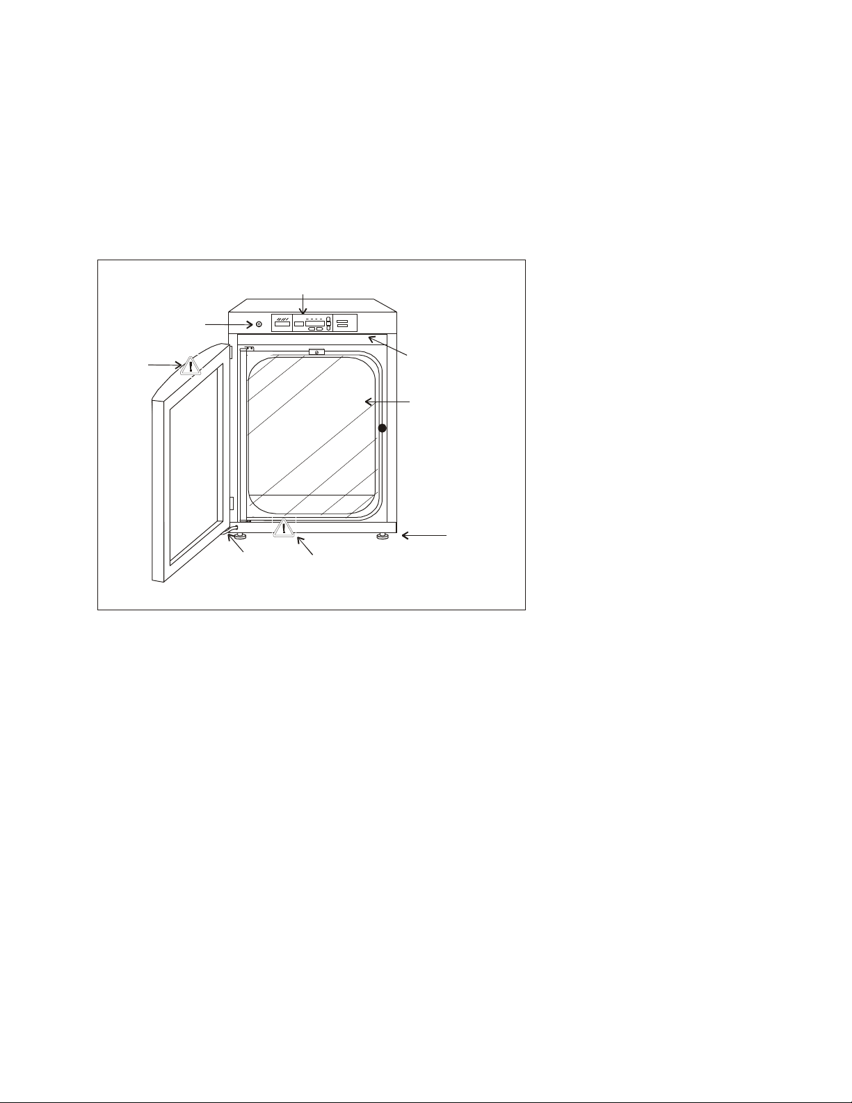
1.1 Incubator Components
•Outer Door - Reversible to
opposite swing, see Section 5.5
•Inner Door - Reversible to opposite
swing, see Section 5.5
•Chamber Gas Sample Port - Used
for sampling chamber CO2content
using a FYRITE or similar
instrument.
•Main Power Switch
•Control Panel - Keypad, Displays
and indicators (See Figure 1-2)
•Leveling Legs - Used to level the
unit
Note: The incubators are stackable. See
Section 1.5.b.
InnerD oor
Leveling
Legs (4 )
DoorHeater
Cable
Contro l Panel
ChamberGas
Sam ple Port Power
Switch
See Section 5
See
Section
1.5
Figure 1-1
FormaModel 310 Series
Direct Heat Incubator

FormaModel 310 Series _______________________________________ Installation Start-Up
1-2
1.2 Control Panel Keys, Displays and Indicators
1. Silence - Silences the audible alarm.
2. Alarm Indicator - Light pulses on/off
during an alarm condition in the cabinet.
3. Mode Select Switch - Used to select
Run, Setpoints, Calibration and System
Configuration Modes.
4. Message Center - Displays system
status.
5. Mode Select Indicators -
Run: Run Menu
Set: Set Points Menu
Cal: Calibrate Menu
Config: Configuration Menu
6. Up and Down Arrows - Increases or
decreases the number values, toggles
between choices.
7. Enter - Stores the value into computer
memory.
8. Heat Indicator - Lights when power is
applied to the heaters.
9. Temp Display - Program to display
temperature continuously, RH
continuously (with RH option), or toggle
between temperature and humidity (with
RH option). See Section 3.1,
Configuration.
10. Scroll for Parameters Arrows - Moves
the operator through the choices of the
selected mode.
11. CO2 Inject Indicator - Lights when CO2
is being injected into the incubator.
12. % CO2Display - Displays CO2
percentage continuously.
Silence M ode
System OK
36.9
4.9
Enter
R un Set C al C onfig H eat Tem p
In ject % CO
2
Scrollfo r P a ra m e te rs
2
3
4
56
7
89
12
11
10
Figure 1-2
Control Panel
FormaModel 310 Series _______________________________________ Installation Start-Up
1-3
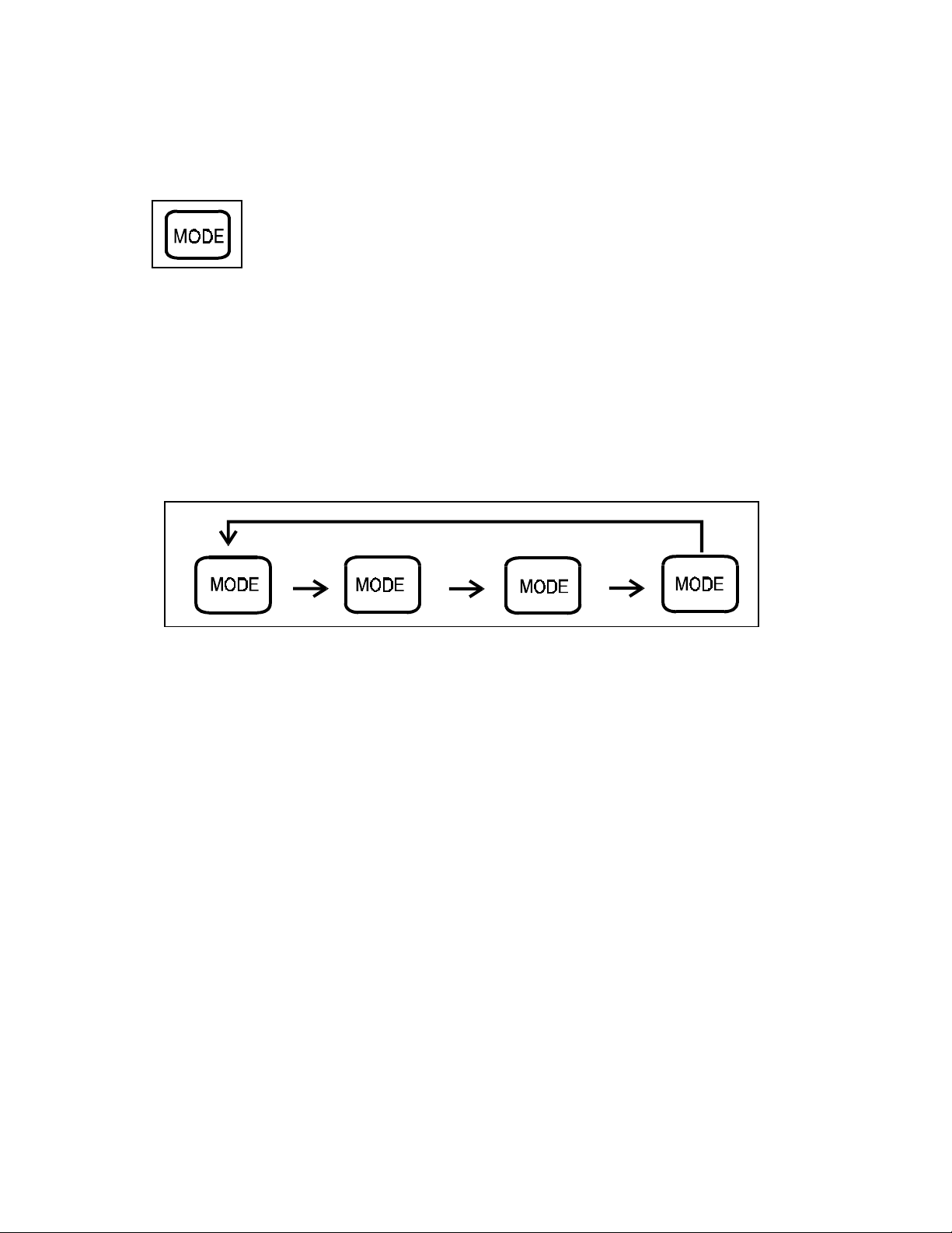
1.3 Operation of the Keypad
The Model 310 Series direct heat incubator has four basic modes which allow
incubator setup: Run, Setpoints, Calibration and System Configuration.
Run is the default mode which the incubator will normally be in during operation.
Set is used to enter system setpoints for incubator operation.
Calibration is used to calibrate various system parameters.
Configuration allows for custom setup of various options.
The chart below shows the selections under each of the modes.
RUN SETPOINT CALIBRATION CONFIGURATION
Default Mode
Temperature
Temp Offset
Audible
Overtemp
CO2Cal1
Access Code
CO2
IR Cal2
Temp Lo Alarm
RH Cal
Temp Relay
CO2Lo Alarm
CO2Hi Alarm
CO2Relay
CO2Z & S #’s *
RH Lo Alarm
RH Relay
Display Temp
Display Rh
Tank Select
Gas Guard
RS485 Address
1T/C units only Base Unit Displays
2IR units only Option Displays
*T/C units only
FormaModel 310 Series _______________________________________ Installation Start-Up
1-4
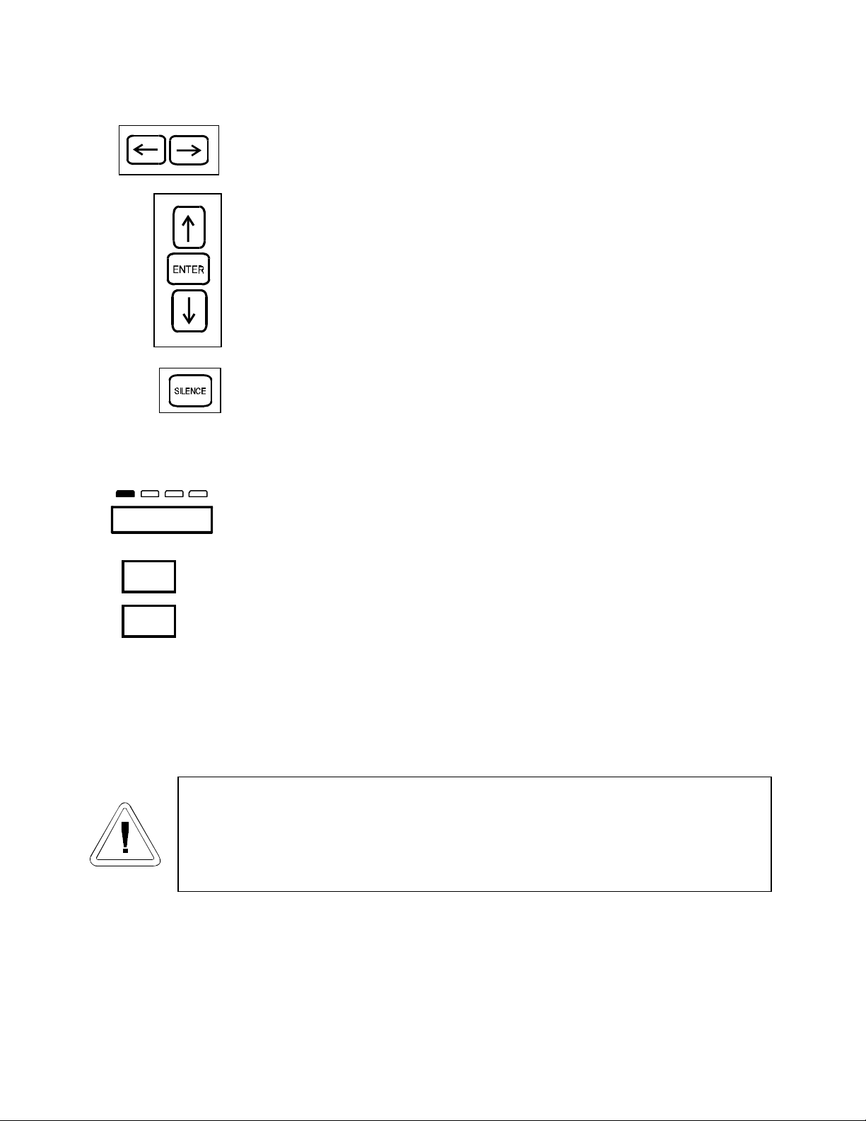
Scroll for Parameters Arrows: Steps the operator through the parameters
of SET, CAL and CONFIG Modes. The right arrow goes to the next
parameter, the left arrow returns to the previous parameter.
Up Arrow: Increases or toggles the parameter value that has been selected
in the SET, CAL, and CONFIG Modes.
Enter: Must press Enter key to save to memory all changed values.
Down Arrow: Decreases or toggles the parameter values that have been
selected in the SET, CAL and CONFIG Modes.
Silence Key: Press to silence the audible alarm. See Section 4 for alarm
ringback times.
1.4 Displays
Message Center - Displays the system status (Mode) at all times. Displays
SYSTEM OK during normal operation, or alarm messages if the system
detects an alarm condition. See Section 4.1, Alarms.
Upper and Lower Displays - These 7 segment displays vary depending
upon the options present and the configuration chosen. The upper display can
display temp or RH, or toggle between them. The bottom display shows CO2
continuously.
1.5 Installing the Incubator
a. Choosing the Location
Single and stacked units must be installed against a wall or similar
structure. Maintain a three-inch clearance behind the incubator for
electrical and gas hook-ups.
1. Locate the unit on a firm level surface capable of supporting the unit’s weight of 205 lbs.
2. Locate the unit away from doors and windows and heating and air conditioning ducts.
3. Lift the unit only by the sides of the cabinet base . Do not attempt to lift it by the front and back .
This places stress on the outer door hinges.
SYSTEM OK
Run Set C al Config
36.9
4.9
Tem p
% CO
2
FormaModel 310 Series _______________________________________ Installation Start-Up
1-5
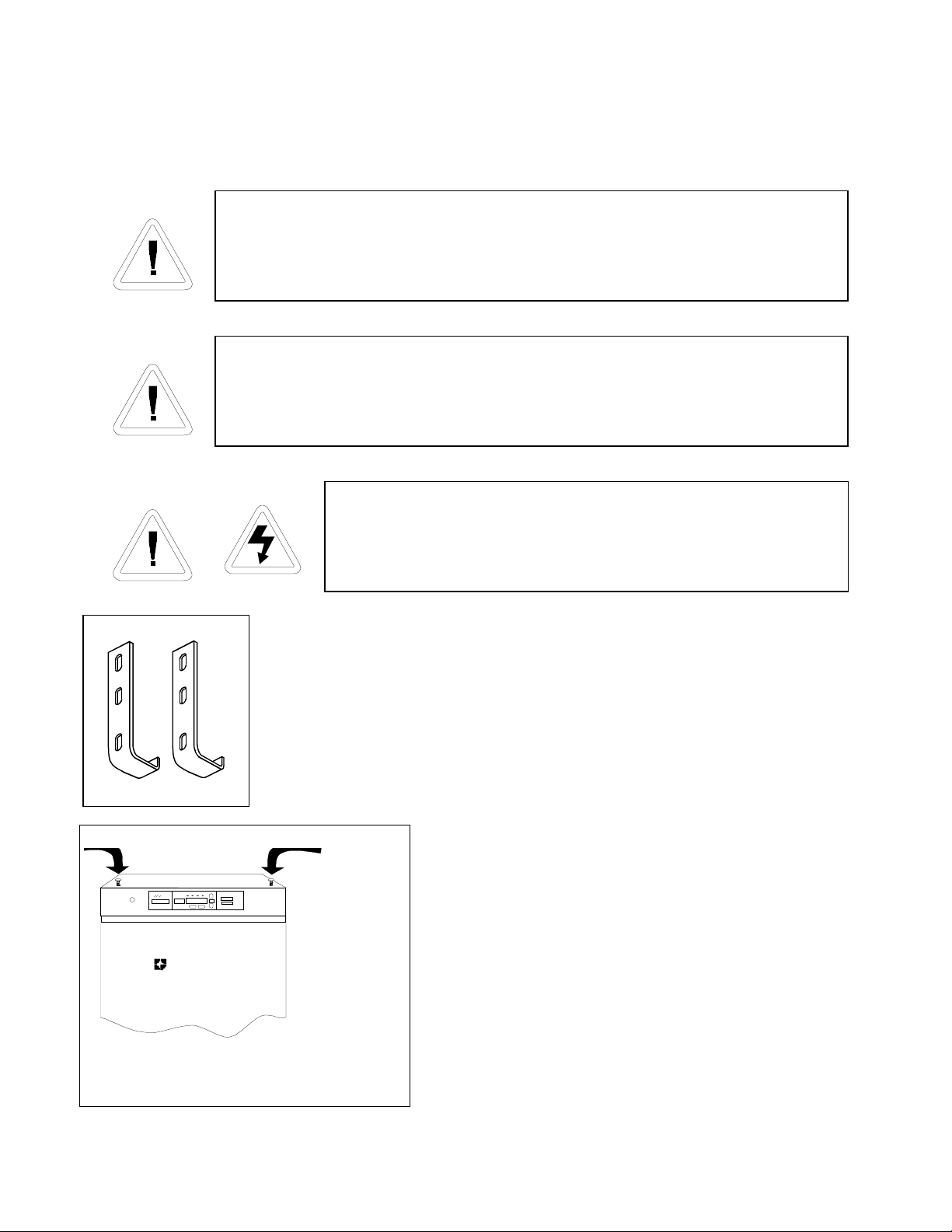
b. Stacking the Incubators
When stacking incubators, the direct heat incubator must be the top unit.
Never stack a water-jacketed incubator on top of a 310 Series unit.
With incubators in a stacked configuration, do not leave both exterior
doors open at the same time.
If the units have been in operation, shut them both off
and pull the plugs before beginning any service work..
Note: Two stacking brackets (shown at left) are included in the parts bag
included with each incubator.
1. Unscrew the slotted head screws on the top of the
bottom incubator about an inch. Refer to Figure 1-4.
2. Unscrew and remove the leveling feet from the top
unit and lift it onto the bottom unit, offsetting the base
of the top unit approximately 2-3 inches behind the
screws identified by the arrows in Figure 1-4.
3. Remove the kickplate from the top incubator. A
Phillips screw on either end secures the plate. Note that
the bottom of the incubator frame is notched.
Figure 1-3
FormaScientific
Figure 1-4

FormaModel 310 Series _______________________________________ Installation Start-Up
1-6
This incubator weighs 205 lbs. Have sufficient personnel when
lifting.
Lift the unit only by the sides of the cabinet base. Do not attempt
to lift it by the front and back as this places stress on the outer
door hinge.
4. Align the sides of the top unit with the
bottom unit and slide the top unit forward
until the notches in the base of the top unit
align with the (2) slotted screws in the top of
the bottom unit. Refer to Figure 1-5.
5. Remove the four nylon plugs on the
lower portion of the back of the upper
incubator.
6. Insert the stacking brackets into the slots
on the back of the control panel of the bottom
unit as shown in Figure 1-6. Align the slots
in the brackets with the mounting holes on
the back of the top incubator. Secure the
brackets with the screws provided in the
stacking kit.
7. Replace the kick plate on the top unit, taking care not to crimp the door heater cable.
8. The stacked incubators are ready for service.
Form a Scien tific
(2 ) slotted screw s
Figure 1-5
Figure 1-6
Back oftop incubator
Back ofbottom incubator
Stacking bracketsStacking brackets
Removevinylplugs
and insertscrews Removevinylplugs
and insertscrews
FormaModel 310 Series _______________________________________ Installation Start-Up
1-7
c. Preliminary Cleaning and Disinfecting
1. Remove the protective plastic coating on the shelf supports and air duct, if present.
2. Using a suitable laboratory disinfectant, disinfect all interior surfaces including shelves
and shelf supports, door gaskets, blower wheel and CO2 sensor. Refer to Section 5.1.
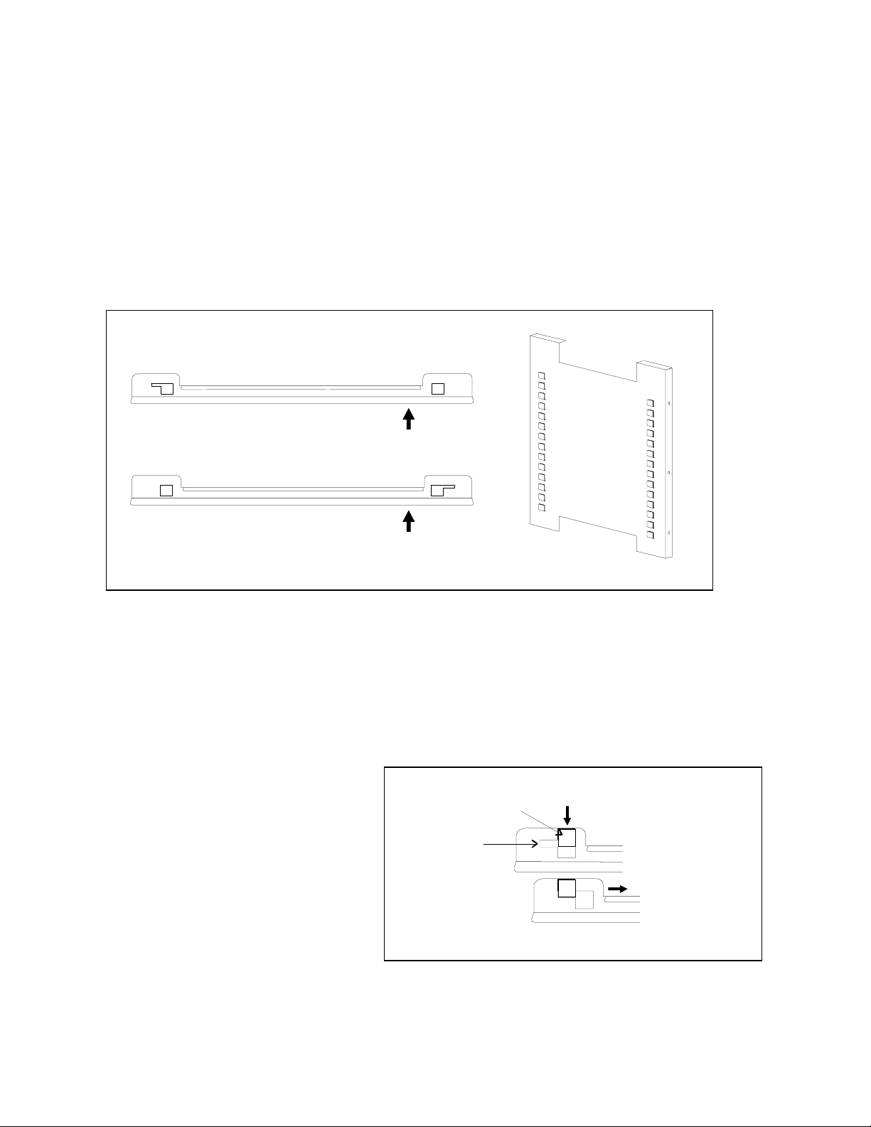
d. Installing the Shelves
1. Install the large sheet metal shelf supports with the tabs facing into the center of the
chamber with their slots up. There are no right side or left side supports, simply turn one
of them to fit the opposite side. Tilt the shelf supports as they are placed in the chamber
so the tops fit into the top air duct, then guide them into the vertical position. Figure 1-7
shows the support as it would be oriented for the right side of the chamber.
2. Referring to Figure 1-7, note that there are left side and right side shelf channels.
3. Install the shelf channels by
placing the channel’s rear slot
over the appropriate rear tab
on the shelf support. Pull the
shelf channel forward and
engage the channel’s front
slot into the shelf support’s
appropriate forward tab.
Refer to Figure 1-8.
Right Shelf Channel
Left Shelf Channel
Shelf Support
Figure 1-7
shelf support
tab
shelf channel
rear slot right side
shelf channel
Figure 1-8
FormaModel 310 Series _______________________________________ Installation Start-Up
1-8
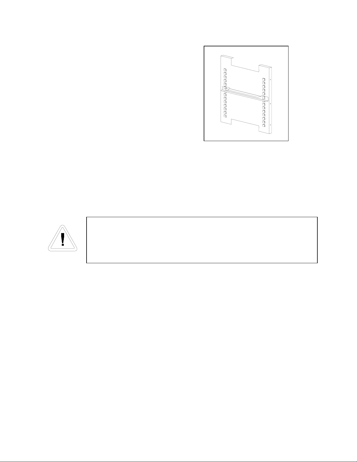
Figure 1-9 shows one of the channels installed on
the right shelf support.
e. Installing the Access Port Filter
Locate the opening in the top left corner of the interior chamber. Install the smaller,
beveled end of the stopper into the opening. See Figure 1-11.
f. Installing the (optional) HEPA Filter
Use caution when handling the filter. The media can be damaged if it is
mishandled.
To avoid damage to the incubator, do not operate the unit without the
HEPA filter in place.
1. Remove the filter from the shipping box.
2. Remove the plastic coating from the filter, using caution not to touch the filter media.
3. Install the filter as shown in Figure 1-10. Refer to Section 5.6 for HEPA filter
maintenance.
Figure 1-9

FormaModel 310 Series _______________________________________ Installation Start-Up
1-9
g. Leveling the Unit
Check for level by placing a bubble style level on one of the shelves. Turn the hex nut on
the leveler counterclockwise to lengthen the leg or clockwise to shorten it. Level the unit
front-to-back and left-to-right.
h. Connecting the Unit to Electrical Power
See the serial tag on the side of the unit for electrical specifications or refer to the
electrical schematics at the end of this manual.
Connect the incubator to a grounded, dedicated circuit.
The power cord connector is the mains disconnect device for the incubator.
Position the incubator so the unit can be easily disconnected.
Plug the provided power cord into the power inlet connector on the back of the cabinet
(See Figure 1-12), then into the grounded, dedicated, electrical circuit.
Access Port Filter Figure 1-11
Blowerfan inlet
HEPA filter
HEPA Filter Figure 1-10
Install in the access
port from the inside
of the incubator
FormaModel 310 Series _______________________________________ Installation Start-Up
1-10
i. Filling the Humidity Pan
Fill the humidity pan with sterile distilled water to within 1/2” of the top. Place the pan
directly in the center of the incubator floor to ensure best humidity and temperature response.
For applications requiring abnormally high humidity, the pan should be placed against the
left side wall of the incubator. The ductwork has been modified to allow the pan to be placed
against the wall of the incubator. In some ambient conditions, this may cause condensation to
form in the chamber.
For best operation of the incubator, sterilized distilled, demineralized or de-ionized water
should be used in the humidity pan. Water purity should be in the resistance range of 50K
Ohm/cm to 1M Ohm/cm, or a conductivity range of 20.0 uS/cm to 1.0 uS/cm. Refer to ASTM
Standard D5391-93 or D4195-88 for measuring water purity.
Distillation systems, as well as some types of reverse osmosis water purity systems, can
produce water in the quality range specified. Tap water is not recommended as it may contain
chlorine, which can deteriorate the stainless steel. Tap water may also have a high mineral
content, which would produce a build-up of scale in the reservoir. High purity, ultra pure or
milli-q water is not recommended as it is an extremely aggressive solvent and will deteriorate the
stainless steel. High purity water has a resistance of above 1M Ohm to 18M Ohm. Even high
purity water can contain bacteria and organic contaminants. Water should always be sterilized or
treated with a decontaminant, safe for use with stainless steel as well as safe for the product,
prior to being introduced into the humidity pan.
Check the level and change the water frequently to avoid contamination. Do not allow the
water level to fluctuate significantly. “Dry-outs” will have an adverse effect on the humidity
level and CO2calibration of the T/C units.
See
Section
1.5, 1.6
and 5
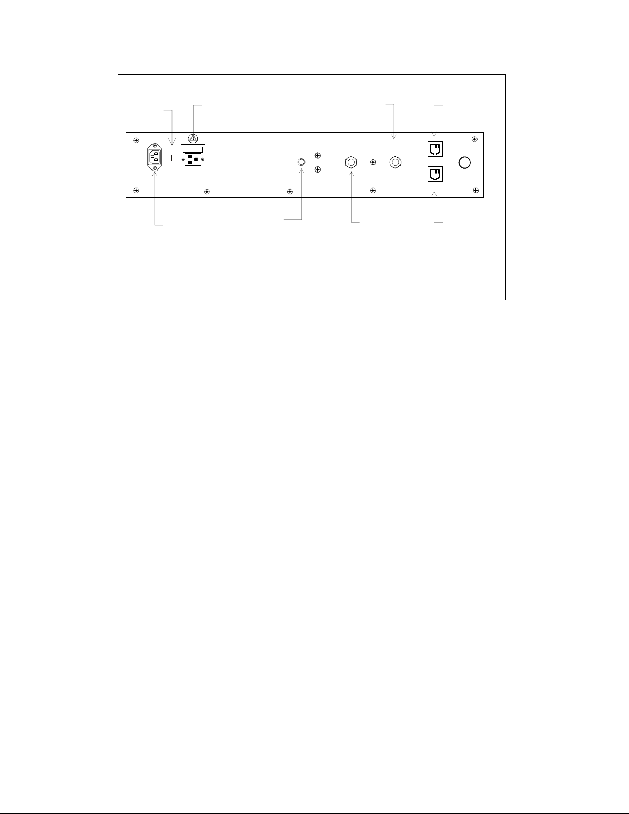
Accessory
Outlet
(75 watts max.)
ACCESSORY
75 WATTS MAX
.
RS 485
ALARM CONTACTS
30V MAX / 1A MAX
#2
CO in
j
ect
15
p
.s.i. Re
g
ulated
(103.4 kPa)
#1
CO in
j
ect
15
p
.s.i. Re
g
ulated
(103.4 kPa)
22
a
b
RJ-ll tele
p
hone st
y
le connectors
Used with the o
p
tional Gas Guard S
y
stem
IR CO Units onl
y
c
2
O
p
tional
RS 485
CO Inlet
#1 Tank
CO Inlet
#2 Tank
Remote
A
larms
A
ir
Intake
Power Cord
Connector
b
b
a
a
2
2
c
Figure 1-12

FormaModel 310 Series _______________________________________ Installation Start-Up
1-11
j. Connecting the CO2Gas Supply
High concentrations of CO2gas can cause asphyxiation!
OSHA Standards specify that employee exposure to carbon dioxide in any eight-hour
shift of a 40-hour work week shall not exceed the eight-hour time weighted average of 5000
PPM (0.5% CO2). The short term exposure limit for 15 minutes or less is 30,000 ppm (3%
CO2). Carbon dioxide monitors are recommended for confined areas where concentrations
of carbon dioxide gas can accumulate.
This incubator is designed to be operated with CO2gas only. Connecting a
flammable or toxic gas can result in a hazardous condition.
Gases other than CO2should not be connected to this equipment. CO2gas cylinders
have a UN1016 label on the cylinder and are equipped with a CGA 320 outlet valve. Check
the gas cylinder for the proper identification labels. The CO2gas supply being connected to
the incubator should be industrial grade, 99.5% pure. Do not use CO2gas cylinders
equipped with siphon tubes. A siphon tube is used to extract liquid CO2from the cylinder
which can damage the pressure regulator. Consult with your gas supplier to ensure that the
CO2cylinder does not contain a siphon tube. Gas cylinders should also be secured to a wall
or other stationary object to prevent them from tipping.
A two-stage CO2pressure regulator is required to be installed on the outlet valve of the
gas cylinder. Input pressure to the incubator must be maintained at 15 psig (103.4 kPa) for
proper performance of the CO2control system. A single stage CO2pressure regulator will
not maintain 15 psig (103.4 kPa) to the incubator as the pressure in the CO2cylinder
decreases; therefore, a two stage regulator is recommended.
If higher purity CO
2is desired inside the incubator (greater than 99.5% pure), the
pressure regulator should be constructed with a stainless steel diaphragm, along with
specifying the purity of the CO2from the gas supplier. Follow the manufacturer’s
instructions to ensure proper and safe installation of the pressure regulator on the gas
cylinder.
Consult your facility safety officer to ensure that the equipment is installed in
accordance with the codes and regulations that are applicable in your area.
Distilled or de-ionized water used in the humidity pan must be within a water
quality resistance range of 50K Ohm/cm to 1M Ohm/cm to protect and
prolong the life of the stainless steel. Use of water outside the specified range
will decrease the operating life of the unit and may void the warranty.

FormaModel 310 Series _______________________________________ Installation Start-Up
1-12
The CO2gas supply being connected should be industrial grade 99.5% pure and should
not contain siphon tubes. Install a two-stage pressure regulator at the cylinder outlet. The
high pressure gauge at the tank should have 0-2000 psig range. The low pressure gauge, at
the incubator inlet, should have a 0-30 psig range. Input pressure to the incubator must be
maintained at 15 psig (103.4 kPa).
The incubator has serrated fittings on the back of the cabinet to connect the gas supply.
Refer to Figure 1-12. The fitting is labeled CO2Inlet #1 Tank. Make sure that the
connections are secured with clamps. Check all fittings for leaks.
For units having the CO2Gas Guard option, refer to Section 6.2.
1.6 Incubator Start-Up
With the incubator properly installed and connected to power, the humidity pan filled,
and the unit connected to gas supplies, system setpoints can be entered. The following
setpoints can be entered in Set mode: Temperature, Overtemperature and CO2. To enter Set
mode, press the Mode key until the Set indicator lights. Press the right and/or left arrow
keys until the proper parameter appears in the message center. See Chart 1-1 for more
detail.
a. Setting the Operating Temperature
All 310 Series incubators have an operating temperature range of 10°C to 50°C,
depending on ambient temperature. The incubator is shipped from the factory with a
temperature setpoint of 10°C. At this setting, all heaters and alarms are turned off. To
change the operating temperature setpoint:
1. Press the Mode key until the Set indicator lights.
2. Press the right arrow until “Temp XX.X” is displayed in the message center.
3. Press the up/down arrow key until the desired temperature setpoint is displayed.
4. Press Enter to save the setpoint.
5. Press the Mode key until the Run indicator lights for Run mode or press the right/left
arrow keys to go to next/previous parameter.
Table of contents
Other Forma Scientific Accessories manuals

Forma Scientific
Forma Scientific 3158 User manual

Forma Scientific
Forma Scientific 3980 User manual

Forma Scientific
Forma Scientific 3980 User manual

Forma Scientific
Forma Scientific 3158 User manual

Forma Scientific
Forma Scientific 3920 Operating instructions

Forma Scientific
Forma Scientific 3980 User manual

Forma Scientific
Forma Scientific 3940 User manual

Forma Scientific
Forma Scientific 3950 User manual

Forma Scientific
Forma Scientific 3940 Operating instructions

Forma Scientific
Forma Scientific 3546 User manual


