Forma Scientific 3250 User manual

-~
ARTISAN
®
~I
TECHNOLOGY
GROUP
Your definitive source
for
quality
pre-owned
equipment.
Artisan Technology
Group
Full-service,
independent
repair
center
with
experienced
engineers
and
technicians
on staff.
We
buy
your
excess,
underutilized,
and
idle
equipment
along
with
credit
for
buybacks
and
trade-ins
.
Custom
engineering
so
your
equipment
works
exactly as
you
specify.
•
Critical
and
expedited
services
•
Leasing
/
Rentals/
Demos
• In
stock/
Ready-to-ship
•
!TAR-certified
secure
asset
solutions
Expert
team
ITrust
guarantee
I
100%
satisfaction
All
tr
ademarks,
br
a
nd
names, a
nd
br
a
nd
s a
pp
earing here
in
are
th
e property of
th
e
ir
r
es
pecti
ve
ow
ner
s.
Find the Thermo / Forma Scientific 3250 at our website: Click HERE

Forma Scientific, Inc.
P.O. Box 649
Marietta, Ohio 45750
U.S.A.
Telephone: (740) 373-4763
Telefax: (740) 373-4189
________________________________________
Model: 3250
Water Jacketed Incubator
Manual No: 7023250 Rev-1
IMPORTANT!
READ THIS INSTRUCTION MANUAL
Failure to read, understand and follow the instructions in this manual may result in
damage to the unit, injury to operating personnel and poor equipment performance.
Artisan Technology Group - Quality Instrumentation ... Guaranteed | (888) 88-SOURCE | www.artisantg.com

Forma Scientific, Inc.______________________________________________________
i
NOTE:
The material in this manual is for information purposes only. The contents and the
product it describes are subject to change without notice. Forma Scientific, Inc. makes no
representations or warranties with respect to this manual. In no event shall Forma
Scientific, Inc. be held liable for any damages, direct or incidental, arising out of or
related to the use of this manual.
MANUAL NO 7023250 Rev-1
112/95 CE Mark added
4/93 Standard Manual
REV ECN DATE DESCRIPTION
Artisan Technology Group - Quality Instrumentation ... Guaranteed | (888) 88-SOURCE | www.artisantg.com

Forma Scientific, Inc.______________________________________________________
ii
GENERAL SAFETY NOTES
~ The Occupational Safety and Health Administration (O.S.H.A.) of the United States has
revised Section 1910-147, "THE CONTROL OF HAZARDOUS ENERGY
(LOCKOUT/TAGOUT)".
NOTE: Hazardous energy may be: ELECTRIC, AIR, HYDRAULIC, WATER,
STEAM, GRAVITY, SPRING & ALL OTHER EQUALLY HAZARDOUS
ENERGY.
This revised regulation, states that you will de-energize all potential sources of energy
(may be more than one energy source) prior to performing service or maintenance on
any equipment. It also states that a lock shall be placed on the de-energized control,
along with a verified test (use of a voltmeter or other equipment) to insure no
accidental starts. If you are not familiar with this regulation, please review the
O.S.H.A. REGULATION, SECTION 1910-147.
In field service, full compliance with this regulation is difficult at best. Troubleshooting
must often be performed with hazardous energy applied; therefore extreme caution
must be followed during these troubleshooting steps. ONLY QUALIFIED
PERSONNEL MUST PERFORM THIS WORK. This phase of the repair work must be
coordinated through the customer's facilities maintenance department or designated
person.
When performing service or maintenance as an outside contractor/worker, follow the
Outside Work Force's Lockout/Tagout system. Be alert for new types of lockout/tagout
devices.
~ Always use the correct personnel protective equipment (clothing, gloves, goggles etc.).
~ Always dissipate extreme cold or heat, or wear protective clothing.
~ Always follow good hygiene practices.
~ Each individual is responsible for his/her own safety.
FOR YOUR SAFETY PLEASE ADHERE TO ALL "DANGER" AND
"CAUTION" STATEMENTS. FAILURE TO DO SO WILL LEAD TO BODILY
INJURY OR PROPERTY DAMAGE OR BOTH. FAILURE TO COMPLY CAN
RESULT IN DISCIPLINARY ACTION.
Danger: This word is used to call attention to immediate hazards of equipment or conditions
which, if not avoided, could result in personal injury, loss of life or property damage.
Caution: This word is used to call attention to potential hazards of equipment or conditions
which, if not avoided, could result in personal injury, loss of life or property damage.
Artisan Technology Group - Quality Instrumentation ... Guaranteed | (888) 88-SOURCE | www.artisantg.com

Forma Scientific, Inc.______________________________________________________
iii
Table of Contents
SECTION 1 - RECEIVING
1.1 Preliminary Inspection ..................................................................................1-1
1.2 Visible Loss or Damage................................................................................1-1
1.3 Responsibility for Shipping Damage ............................................................1-1
1.4 Unpacking List for Model 3250.....................................................................1-2
SECTION 2 - INSTALLATION AND START-UP
2.1 Location .........................................................................................................2-1
2.2 Reversing the Door Swing .............................................................................2-1
2.3 Preliminary Disinfecting ................................................................................2-5
2.4 Installing the Side Shelf Supports..................................................................2-5
2.5 Installing the Shelves .....................................................................................2-6
2.6 Leveling .........................................................................................................2-7
2.7 Stacking the Incubators..................................................................................2-8
Stacking Incubators - Early Production Series...............................................2-8
Stacking Incubators- Mixed Production Series..............................................2-9
2.8 Installing the Power Cord ..............................................................................2-12
2.9 Connecting to Power......................................................................................2-12
2.10 Preparing the Incubator for Filling...............................................................2-13
2.11 Filling the Water Jacket ...............................................................................2-13
2.12 Filling the Humidity Pan..............................................................................2-15
2.13 Connecting the CO2Supply ........................................................................2-15
2.14 Access Port...................................................................................................2-17
2.15 RS - 232 Computer Interface (Optional)......................................................2-17
2.16 Remote Alarm Contact ................................................................................2-19
2.17 Analog Recorder Output ..............................................................................2-19
2.18 Accessory Outlet ..........................................................................................2-20
Artisan Technology Group - Quality Instrumentation ... Guaranteed | (888) 88-SOURCE | www.artisantg.com

Forma Scientific, Inc.______________________________________________________
iv
SECTION 3 - OPERATION
3.1 Factory Settings.............................................................................................3-1
3.2 Overview of Controls....................................................................................3-1
a. Power Switch/Resettable Circuit Breaker...............................................3-1
b. Over Temp Setpoint Adjustment Tool.....................................................3-2
c. Audible Alarm.........................................................................................3-2
d. Drain Valve.............................................................................................3-2
3.3 Operation of "SET" Modes ...........................................................................3-4
Temperature Set Sequence............................................................................3-4
CO2Set Sequence.........................................................................................3-5
Overtemp Set Sequence ................................................................................3-6
Door Heat Set Sequence ...............................................................................3-7
Start-Up Set Sequence ..................................................................................3-10
Audible Alarm Enable/Disable Sequence.....................................................3-12
Humidity (RH) Set Sequence........................................................................3-14
Remote Alarm Set Sequence ........................................................................3-16
3.4 Alarms...........................................................................................................3-18
3.5 Overview of Humidification and CO2..........................................................3-20
SECTION 4 - ROUTINE MAINTENANCE
4.1 Disinfecting the Incubator Interior................................................................4-1
4.2 Cleaning the Cabinet Exterior.......................................................................4-2
SECTION 5 - CALIBRATION PROCEDURES
5.1 Calibration Frequency...................................................................................5-1
5.2 Calibrating the %CO2Zero ..........................................................................5-1
5.3 Calibrating the %CO2Span..........................................................................5-3
5.4 Calibrating the New CO2Sensor..................................................................5-4
5.5 Calibrating the Temperature Offset ..............................................................5-6
5.6 Changing the Access Code ...........................................................................5-7
Artisan Technology Group - Quality Instrumentation ... Guaranteed | (888) 88-SOURCE | www.artisantg.com

Forma Scientific, Inc.______________________________________________________
v
SECTION 6 - TESTING PROCEDURES
6.1 Heater Test ....................................................................................................6-1
6.2 CO2Valve Test.............................................................................................6-3
6.3 Display Jacket Temperature Test..................................................................6-4
6.4 Overtemp Setpoint Test ................................................................................6-5
6.5 A/D Converter Reference Test......................................................................6-6
6.6 ROM (Eprom) Test .......................................................................................6-7
6.7 RAM Test......................................................................................................6-8
6.8 EEPROM Test ..............................................................................................6-9
6.9 Reload EEPROM..........................................................................................6-10
SECTION 7 - SERVICE
Caution: Actual servicing of the unit must be performed by qualified service
personnel!
7.1 Replacing the Blower Wheel ........................................................................7-1
7.2 Replacing the Bacterial Air Vent Filter ........................................................7-1
7.3 Replacing the Blower Motor.........................................................................7-2
7.4 Replacing the CO2Valve .............................................................................7-3
7.5 Replacing the Inline CO2Filter ....................................................................7-3
7.6 Replacing the Chamber Air Sensor Probe ....................................................7-4
7.7 Replacing the Water Jacket Sensor Probe.....................................................7-5
7.8 Replacing the CO2Sensor .............................................................................7-6
7.9 Replacing the Water Float Switch ................................................................7-7
7.10 Replacing the Microprocessor Board...........................................................7-8
7.11 Replacing the Fuse(s)...................................................................................7-8
7.12 Replacing the Display Board and Assembly................................................7-9
SECTION 8 - SPECIFICATIONS AND ACCESSORIES
SECTION 9 - PARTS LIST
SECTION 10 - SCHEMATICS
Artisan Technology Group - Quality Instrumentation ... Guaranteed | (888) 88-SOURCE | www.artisantg.com

Forma Scientific, Inc.______________________________________________________
1-1
SECTION 1 - RECEIVING
1.1 Preliminary Inspection
This item was thoroughly inspected and carefully packed prior to shipment and all
necessary precautions were taken to ensure safe arrival of the merchandise at its
destination. Immediately upon receipt, before the unit is moved from the receiving area,
carefully examine the shipment for loss or damage. Unpack the shipment and inspect both
interior and exterior for any in-transit damage.
1.2 Visible Loss or Damage
If any loss or damage is discovered, note any discrepancies on the delivery receipt.
Failure to adequately describe such evidence of loss or damage may result in the carrier
refusing to honor a damage claim.
Immediately call the delivering carrier and request that their representative perform an
inspection. Do not discard any of the packing material and under no circumstances move
the shipment from the receiving area.
1.3 Responsibility for Shipping Damage
For products shipped F.O.B. Marietta, Ohio, the responsibility of Forma Scientific, Inc.
ends when the merchandise is loaded onto the carrier's vehicle.
On F.O.B. Destination shipments, Forma Scientific's and the carrier's responsibility ends
when your Receiving Department personnel signs a free and clear delivery receipt.
Whenever possible, Forma Scientific, Inc. will assist in settling claims for loss or in-
transit damage.
Artisan Technology Group - Quality Instrumentation ... Guaranteed | (888) 88-SOURCE | www.artisantg.com

Forma Scientific, Inc.______________________________________________________
1-2
1.4 Unpacking List for Model 3250
If the unit is to be moved by fork lift, leave the incubator on the skid until it has been
moved to its designated location. The following items are packed within the incubator:
Item Part# Description
1 115018 3/16" Round Stainless Steel Handle
2 22115 6-32 X 1/4" Stainless Steel Screw (Mounting Handle)
3 950013 1/4" ID Vinyl Tubing ( CO2Supply)
4 190325 Stacking Brackets
5 195125 Bacterial Air Vent (Decontamination Kit)
6 600034 .375" Snapper Hose Clamp (CO2 Supply)
7 18001 Polypropylene Funnel (Filling Incubator)
8 Line Cord
9 100078 Blower Wheel (1.95 X .625 CCW) (Decontamination Kit)
10 246011 3/8" Vinyl Tubing (Filling Incubator)
11 380284 3/8" Hose X 1/4" MPT Nylon Adapter (Drain Valve Fitting)
12 3250-45-1 Shelf Support (2) Total
13 237013 Humidity Pan
14 224140 Electro Polished Stainless Steel Shelves (5) Total
15 190398 Stacking Pins (2)
16 190388 Telephone Line Cord 12 FT (2)
17 190392 RJ-11 To Screw Terminal Cover (2)
Artisan Technology Group - Quality Instrumentation ... Guaranteed | (888) 88-SOURCE | www.artisantg.com

Forma Scientific, Inc._____________________________________________________
2-1
SECTION 2 - INSTALLATION AND START-UP
2.1 Location
Locate the incubator in a draft-free area away from doors, windows, or air
conditioning/heating ductwork. To help prevent microbial contamination, the incubator
should also be removed from areas of high personnel traffic.
Place the unit on a firm, level surface capable of supporting the water filled unit.
(Approximate weight with water = 342 lbs or 155 kgs).
Note: Adequate space is required behind the incubator for installation (electrical and gas
connections) and service.
2.2 Reversing the Door Swing
For side-by-side operation or changing lab layouts, the inner and outer doors are
field reversible. The following steps are sequentially called out on the drawings, located
at the end of this procedure. The procedure is written from the prospective of changing
the door swing from a left-hand to a right-hand swing.
1. Remove the four screws securing the inner door hinges and remove the inner door.
2. Open lower front panel.
3. Locate the retaining rod in the right front corner, securing the lower front panel to the
incubator. Slide the retaining rod out from its mounting bracket.
4. Remove the two screws securing cable cover (below drawer). Remove cable cover
and slide snap bushing and cable out of the end slot. Set cable cover aside.
Note: Do not remove the strain reliefs from the cables. They have been specifically
placed at points on the cable, at the factory.
5. Remove the two screws securing the door cable cover. Remove cable cover and set
aside.
6. With the assistance of a second person or portable table, remove the four screws
securing the outer door hinges to the cabinet. Remove outer door and place it face
down.
Artisan Technology Group - Quality Instrumentation ... Guaranteed | (888) 88-SOURCE | www.artisantg.com

Forma Scientific, Inc.______________________________________________________
2-2
7. Note dimple location in hinge. Remove hinges from outer door. Remove the small
plastic hole plugs from the (reversible swing) hinge mounting holes. Place hole plugs
back into the original hinge mounting holes.
8. Install hinges (same dimple location as when removed) in the reversible swing hinge
mounting holes.
9. Turn door cable cover so that strain relief is on the hinge side of the door. Secure door
cable cover.
10. Remove the eight plastic hole plugs from the front right corner. Reinstall these eight
hole plugs on the left front corner.
11. With the assistance of a second person, align outer door hinges with hinge mounting
holes in cabinet. Secure with the four screws. NOTE: Adjust hinges as necessary to
align door with cabinet.
12. Locate cable cover (previously mounted below drawer) and slide strain relief
bushing/cable back into slot, so that the strain relief bushing is on the hinged side of
the door. Secure cable cover with the two screws.
13. Slide retaining rod back into its mounting bracket.
14. Locate inner door strike on shelf support and remove. Reinstall on opposite shelf
support.
15. Align hinges on inner glass door with mounting holes in cabinet, and secure with four
screws.
Note: The "WARNING" label will be upside down.
16. Loosen nut on back of latch stud and rotate latch tab 180°, then tighten nut.
17. Replace door cable cover.
Artisan Technology Group - Quality Instrumentation ... Guaranteed | (888) 88-SOURCE | www.artisantg.com

Forma Scientific, Inc.______________________________________________________
2-3
Figure 2.1
Artisan Technology Group - Quality Instrumentation ... Guaranteed | (888) 88-SOURCE | www.artisantg.com

Forma Scientific, Inc.______________________________________________________
2-4
Figure 2.1a
Artisan Technology Group - Quality Instrumentation ... Guaranteed | (888) 88-SOURCE | www.artisantg.com

Forma Scientific, Inc.______________________________________________________
2-5
2.3 Preliminary Disinfecting
A clear plastic film on the side shelf supports protects the finish during shipping
and handling. This plastic film must be removed (peeled-off) before protected parts are
disinfected and installed.
Note: Refer to Section 4.1 titled "Disinfecting the Incubator Interior", for specific
instructions.
Before installation, Forma Scientific Inc. recommends disinfecting the following:
shelf supports, shelves, and all interior surfaces including both door gaskets. After
disinfecting, rinse the surfaces with sterile distilled water (50K Ohm to 1 Meg Ohm).
Also disinfect the CO2sensor and the blower wheel (located behind the rear blower
plenum) taking care not to saturate the sensor. Repeat rinsing until you are satisfied that
all of the disinfectant-detergent has been removed. Proceed with the installation as noted.
2.4 Installing the Side Shelf Supports (Refer to Figure 2.1)
Locate the 3/16" round stainless steel handle and the two #6-32 x 1/4" Phillips
head screws (supplied in parts bag). Before installing the side shelf supports, determine
the cabinet door swing (right-hand or left-hand). Position the side shelf supports so that
the notched edges are at the bottom. Mount the handle on the appropriate shelf support by
aligning the handle with the pre-punched holes provided; and use the screws supplied to
secure it.
Note: The handle must align with the door strike of the inner glass door.
Install the (2) side shelf supports with the notched edge to the bottom. Locate the
grooved studs on the right and left interior wall. Align key holes in side shelf support over
grooved studs. Push down on side shelf support to lock into position.
Artisan Technology Group - Quality Instrumentation ... Guaranteed | (888) 88-SOURCE | www.artisantg.com

Forma Scientific, Inc.______________________________________________________
2-6
2.5 Installing the Shelves (Refer to Figure 2.2)
Slide each shelf into the shelf bracket at the desired level. There are a maximum
of 22 positions available, excluding the use of the humidity pan.
Figure 2.2
Artisan Technology Group - Quality Instrumentation ... Guaranteed | (888) 88-SOURCE | www.artisantg.com

Forma Scientific, Inc.______________________________________________________
2-7
2.6 Leveling (Refer to Figure 2.3)
Check leveling by placing a bubble-type level on one of the interior shelves, (level
from side to side and from front to back). Using a 9/16" wrench, adjust the leveling leg
(four total) clockwise (as viewed from above the incubator) to lengthen the leveling leg,
or raise the unit. Turning the adjustment leg counterclockwise will shorten the leg, or
lower the unit.
Note: Be sure to level the incubator, before filling the water jacket.
Caution: To prevent injury to personnel and/or damage to equipment, lock inner
glass door and secure outer door before tipping unit to adjust leveling feet.
Caution: Do not attempt to tilt the incubator without assistance while adjusting the
leveling feet.
Artisan Technology Group - Quality Instrumentation ... Guaranteed | (888) 88-SOURCE | www.artisantg.com

Forma Scientific, Inc.______________________________________________________
2-8
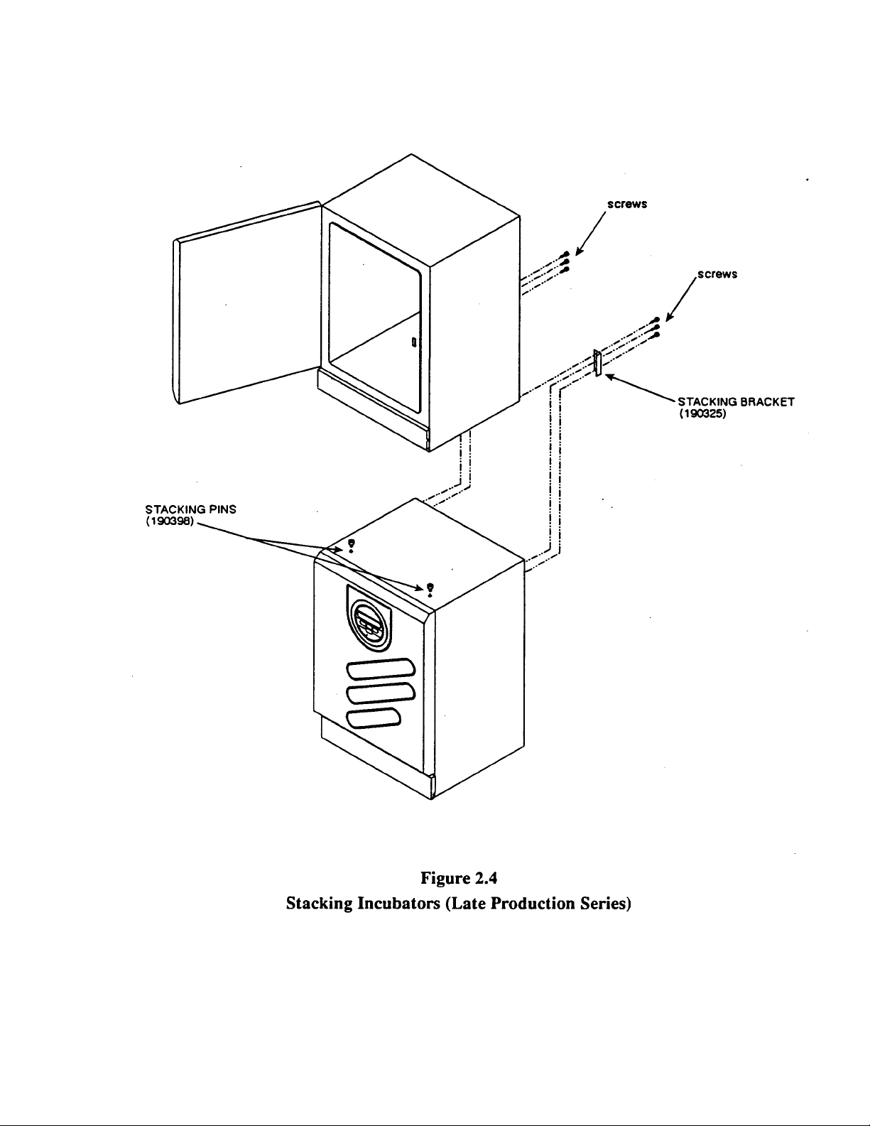
2.7 Stacking the Incubators (Refer to Figure 2.4)
Note: Two stacking pins and two stacking brackets are included in the parts kit
accompanying each incubator.
1. Before placing the top unit into position, unscrew and remove all leveling feet.
Remove the (2) stacking screws from the top panel of the bottom unit.
2. Insert the stacking pins over the. Insert the screws through the stacking pins and
tighten.
3. Stack the top incubator over the bottom unit, offsetting the top unit
2-1/4" to 2-1/2" to the front.
4. Align all sides. Slide the top unit back, engaging the stacking pins into the slots in the
bottom of the top unit.
5. Remove and save the screws from each top rear corner of bottom incubator (4 screws
total). Remote the single screw from each bottom rear corner of the top unit (two
screws total).
6. Attach the stacking brackets onto the back of the incubators using the screws and
screw holes from step 6. . (Refer to Figure 2.4).
Stacking Incubators - Early Production Series
Early production Incubators (Release 1) are stacked and fastened together using
the two stacking brackets on the back of the cabinet and a single stacking screw which
connects the top unit to the bottom unit. Release 1 models are identified by a single
screw on the top of the cabinet. (refer to Figure 2.5a)
1. Remove the single stacking screw located on the top of the lower incubator.
2. Remove the four leveling feet from the incubator to be stacked on top.
3. Place the unit on top of the bottom unit.
4. Open the control panel cover on the top unit.
5. Remove the two screws which hold the control panel in place and pull the drawer out.
6. Position the drawer so that the access hole on the bottom of the drawer is aligned with
the screw hole on the top of the lower incubator.
Artisan Technology Group - Quality Instrumentation ... Guaranteed | (888) 88-SOURCE | www.artisantg.com

Forma Scientific, Inc.______________________________________________________
2-9
7. Insert the stacking screw through the hole and tighten.
8. Remove and save the two screws from each top rear corner of the bottom incubator
(four screws total). Remove and save the single screw from the bottom rear corner of
the top unit (two screws total).
9. Lock the two units together by attaching the stacking brackets onto the back of the
incubators using the screws and screw holes from step 8.
Stacking Incubators - Mixed Production Series
When stacking Release 1 and Release 2 incubators, the Release 1 unit must be
placed on the bottom. The units are fastened together using the two stacking brackets on
the back of the cabinets and a single stacking screw connecting the top unit to the bottom
unit. refer to Figure 2.4 and Figure 2.4a.
1. Remove the single stacking screw located on the top of the lower incubator.
2. Remove the four leveling feet from the incubator to be stacked on top.
3. Place the unit on top of the bottom unit.
4. Open the control panel cover on the top unit.
5. Remove the two screws which hold the control panel in place.
6. Remove the two screws which hold the narrow horizontal plate beneath the control
panel.
7. Remove the control panel by pulling the drawer out and tilting upward. Remove the
drawer completely from the cabinet.
8. Align the top incubator and install the stacking screw into the bottom cabinet to lock
the two units together.
9. Replace the horizontal plate and the control panel drawer ant tighten all screws.
10. Remove and save the two screws from each top rear corner of the bottom incubator (a
total of four screws removed). Remove the single screw from each bottom rear corner
of the top unit (a total of two screws).
11. Attach the stacking brackets onto the back of the incubators using the screws removed
in the previous step.
Artisan Technology Group - Quality Instrumentation ... Guaranteed | (888) 88-SOURCE | www.artisantg.com
Forma Scientific, Inc.______________________________________________________
2-10
Artisan Technology Group - Quality Instrumentation ... Guaranteed | (888) 88-SOURCE | www.artisantg.com

Forma Scientific, Inc.______________________________________________________
2-11
Figure 2.4a
Stacking Incubators (Early Production Series)
Artisan Technology Group - Quality Instrumentation ... Guaranteed | (888) 88-SOURCE | www.artisantg.com
Table of contents
Other Forma Scientific Accessories manuals

Forma Scientific
Forma Scientific 3920 Operating instructions

Forma Scientific
Forma Scientific 3980 User manual

Forma Scientific
Forma Scientific 3940 Operating instructions

Forma Scientific
Forma Scientific 3920 Operating instructions

Forma Scientific
Forma Scientific 3940 User manual

Forma Scientific
Forma Scientific 3950 User manual

Forma Scientific
Forma Scientific 3911 Operating instructions

Forma Scientific
Forma Scientific 3158 User manual

Forma Scientific
Forma Scientific 3980 User manual

Forma Scientific
Forma Scientific 310 Series Operating instructions


