Forma Scientific 3920 Operating instructions

Model 3920
29 cu. ft. Capacity
Reach-In Incubator
Operating and Maintenance Manual
Manual No: 7013920 Rev. 3

Model 3920 _________________________________________________________________________________
i
Read This Instruction Manual.
Failure to read, understand and follow the instructions in
this manual may result in damage to the unit, injury to operat-
ing personnel, and poor equipment performance.
CAUTION! All internal adjustments and maintenance must
be performed by qualified service personnel.
Refer to the serial tag on the back of this manual.
The material in this manual is for information purposes only.
The contents and the product it describes are subject to change
without notice. Thermo Forma makes no representations or war-
ranties with respect to this manual. In no event shall Thermo
Forma be held liable for any damages, direct or incidental, aris-
ing out of or related to the use of this manual.
MANUAL NUMBER 7013920
-- IN-2103 7/96 Added shipping tape removal heg
3 13426 5/95 Added p-trap to installation heg
2 12158 7/94 Updated refrigeration schematic, parts list and electrical schematic to reflect phenolic-
coated coil now standard
1 -- 4/94 Manual edited to current format
REV ECR/ECN DATE DESCRIPTION By
Model 3920 _________________________________________________________________________________
ii
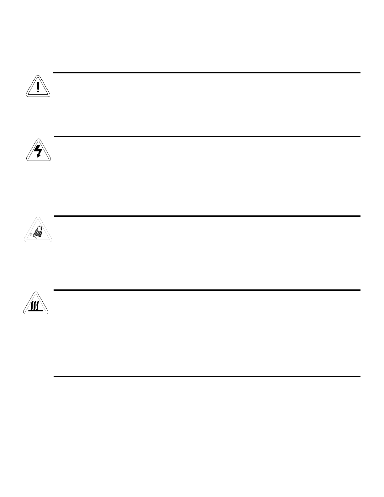
Important operating and/or maintenance instructions. Read the accompanying text carefully.
Ce symbole attire l'attention de l'utilisateur sur des instructions importantes de fonctionnement et/ou d'entretien. Il
peut être utilisé seul ou avec d'autres symboles de sécurité. Lire attentivement le texte d'accompagnement.
Wichtige Betriebs- und/oder Wartungshinweise. Lesen Sie den nachfolgenden Text sorgfältig.
Importante instruccions de operacion y/o mantenimiento. Lea el texto acompanante cuidadosamente.
Potential electrical hazards. Only qualified persons should perform procedures associated with this symbol.
Ce symbole attire l'attention de l'utilisateur sur des risques électriques potentiels. Seules des personnes qualifiées
doivent appliquer les instructions et les procédures associées à ce symbole.
Gefahr von Stromschlägen. Nur qualifizierte Personen sollten die Tätigkeiten ausführen, die mit diesem Symbol beze-
ichnet sind.
Potencial de riesgos electricos. Solo personas das capacitadadas deben ejecutar los procedimientos asociadas con este
simbulo.
Equipment being maintained or serviced must be turned off and locked off to prevent possible injury.
Risques potentiels liés à l'énergie. L'équipement en entretien ou en maintenance doit être éteint et mis sous clé pour
éviter des blessures possibles.
Geräte, an denen Wartungs- oder Servicearbeiten durchgeführt werden, müssen abgeschaltet und abgeschlossen wer-
den, um Verletzungen zu vermeiden.
El equipo recibiendo servicio o mantenimiento debe ser apagado y segurado para prevenir danos.
Hot surface(s) present which may cause burns to unprotected skin, or to materials which may be damaged by elevated
temperatures.
Présence de surface(s) chaude(s) pouvant causer des brûlures sur la peau non protégée, ou sur des matières pouvant
être endommagées par des températures élevées.
Heiße Oberfläche(n) können ungeschützter Haut Verbrennungen zufügen oder Schäden an Materialien verursachen,
die nicht hitzebeständig sind.
Superficias calientes que pueden causar quemaduras a piel sin proteccion o a materiales que pueden estar danados
por elevadas temperaturas.
√ Always use the proper protective equipment (clothing, gloves, goggles, etc.)
√ Always dissapate extreme cold or heat and waer protective clothing.
√ Always follow good hygiene practices.
√ Each individual is responsible for his or her own safety.

Do You Need Information or Assistance on Forma Scientific
Products?
do, please contact us 8:00 a.m. to 7:00 p.m. (Eastern Time) at:
1-740-373-4763 Direct
1-888-213-1790 Toll Free, U.S. and Canada
1-740-373-4189 FAX
http://www.forma.com Internet Worldwide Web Home Page
fservice@forma.com Service E-Mail Address
If you
Our staff can provide information on pricing and give you quotations. We
can take your order and provide delivery information on major equipment items or make
arrangements to have your local sales representative contact you. Our products are listed on the
Internet and we can be contacted through our Internet home page.
Our staff can supply technical information about proper setup,
operation or troubleshooting of your equipment. We can fill your needs for spare or replacement
parts or provide you with on-site service. We can also provide you with a quotation on our
Extended Warranty for your Forma products.
Whatever Forma products you need or use, we will be happy to discuss your
applications. If you are experiencing technical problems, working together, we will help you
locate the problem and, chances are, correct it yourself...over the telephone without a service
call.
When more extensive service is necessary, we will assist you with direct factory trained
technicians or a qualified service organization for on-the-spot repair. If your service need is
covered by the warranty, we will arrange for the unit to be repaired at our expense and to your
satisfaction.
Regardless of your needs, our professional telephone technicians are available to assist
you Monday through Friday from 8:00 a.m. to 7:00 p.m. Eastern Time. Please contact us by
telephone or fax. If you wish to write, our mailing address is:
Forma Scientific, Inc.
Millcreek Road, PO Box 649
Marietta, OH 45750
International customers please contact your local Forma Scientific distributor.
Sales Support
Service Support
Model 3920 _________________________________________________________________________________
iii

Model 3920 _________________________________________________________________________________
iv
Table of Contents
Section 1 - Receiving . . . . . . . . . . . . . . . . . . . . . . . . . . . .2 - 1
1.1 Preliminary Inspection . . . . . . . . . . . . . . . . . . . . . . .2 - 1
1.2 Visible Loss or Damage . . . . . . . . . . . . . . . . . . . . . .2 - 1
1.3 Responsibility for Shipping Damage . . . . . . . . . . . .2 - 1
Section 2 - Installation and Start-Up . . . . . . . . . . . . . . . . .2 - 1
2.1 Location . . . . . . . . . . . . . . . . . . . . . . . . . . . . . . . . . . .2 - 1
2.2 Removing the Shipping Tape . . . . . . . . . . . . . . . . . . .2 - 1
2.3 Attaching the Drain Lines . . . . . . . . . . . . . . . . . . . . . .2 - 1
2.4 Power Connection . . . . . . . . . . . . . . . . . . . . . . . . . . . .2 - 1
2.5 Start-Up Procedure . . . . . . . . . . . . . . . . . . . . . . . . . . .2 - 1
2.6 Setting the Overtemp Safety Thermostat . . . . . . . . . .2 - 2
2.7 Setting the Undertemp Safety Thermostat . . . . . . . . .2 - 2
Section 3 - Control Panel Operation . . . . . . . . . . . . . . . . .3 - 1
3.1 The 3920 Control Panel . . . . . . . . . . . . . . . . . . . . . . .3 - 1
3.2 Temperature Controller . . . . . . . . . . . . . . . . . . . . . . . .3 - 1
Section 4 - Routine Maintenance . . . . . . . . . . . . . . . . . . .4 - 1
4.1 Cleaning the Incubator . . . . . . . . . . . . . . . . . . . . . . . .4 - 1
. . . . . . . . . . . . . . . . . . . . . . . . . . . . . . . . . . . . . . . . . . .5 - 1
Section 5 - Service . . . . . . . . . . . . . . . . . . . . . . . . . . . . . . .5 - 1
5.1 Access to the Electrical Components . . . . . . . . . . . . .5 - 1
5.2 Replacing the Overtemp/Undertemp Probe and
Thermostat . . . . . . . . . . . . . . . . . . . . . . . . . . . . . . . . . . . . .5 - 1
5.3 Replacing the Optional Recorder and Probe(s) . . . . .5 - 1
5.4 Removing the Top Section . . . . . . . . . . . . . . . . . . . . .5 - 1
5.5 Calibration Offset . . . . . . . . . . . . . . . . . . . . . . . . . . . .5 - 3
5.6 Controller Configuration . . . . . . . . . . . . . . . . . . . . . . .5 - 4
5.7 Handling Error Codes on the Microprocessor . . . . . .5 - 7
Section 6 – Specifications . . . . . . . . . . . . . . . . . . . . . . . . .6 - 1
Section 7 - Parts List (specific for each job)
Section 8 - Schematics

2 - 1
Section 1 - Receiving
1.1 Preliminary Inspection
This item was thoroughly inspected and carefully packed
prior to shipment. All necessary precautions were taken to
ensure safe arrival of the merchandise at its destination.
Immediately upon receipt, before the unit is moved from the
receiving area, carefully examine the shipment for loss or dam-
age. Unpack the shipment and inspect both interior and exterior
for any in-transit damage.
1.2 Visible Loss or Damage
If any loss or damage is discovered, note any discrepancies
on the delivery receipt. Failure to adequately describe such evi-
dence of loss or damage may result in the carrier refusing to
honor a damage claim. Immediately call the delivering carrier
and request that their representative perform an inspection. Do
not discard any of the packing material and under no circum-
stances, move the shipment from the receiving area.
1.3 Responsibility for Shipping Damage
For products shipped F.O.B. Marietta, Ohio, the responsi-
bility of Thermo Forma ends when the merchandise is loaded
onto the carrier’s vehicle.
On F.O.B. Destination shipments, Thermo Forma and the
carrier’s responsibility ends when your Receiving Department
personnel sign a free and clear delivery receipt.
Whenever possible, Thermo Forma will assist in settling
claims for loss or in-transit damage.
Section 2 - Installation and Start-Up
2.1 Location
Locate the unit on a firm, level surface in an area of mini-
mum ambient temperature fluctuation. A minimum of 12 inches
clearance is required at the top of the incubator and a minimum
of 3 inches clearance is required at the rear of the incubator to
facilitate adequate airflow around the refrigeration system.
2.2 Removing the Shipping Tape
Adhesive shipping tape is applied to the screws securing
the perforated duct sheet to the rear side wall of the chamber.
Remove this tape when preparing the incubator for operation.
2.3 Attaching the Drain Lines
The Chamber Drain (overflow from
the humification reservoir) is located on
the rear of the cabinet. This drain must be
trapped to prevent CO2drainage from the
chamber. A copper p-trap (Figure 2-1) is
provided with the Model 3920 and must
be installed. Attach vinyl tubing to the p-
trap and route it to an open drain.
2.4 Power Connection
The electrical junction box is located on the rear top sec-
tion of the incubator. With the junction box switch OFF, con-
nect the incubator to an adequate power source. See the electri-
cal data plate mounted on the unit for exact electrical specifica-
tions.
2.5 Start-Up Procedure
Preset the controls as follows:
Overtemp Safety Thermostat . . . . . . . . . . . .(Fully Clockwise)
Undertemp Safety Thermostat . . . . .(Fully Counterclockwise)
Main Power Switch . . . . . . . . . . . . . . . . . . . . . . . . . . . . . . .ON
Temperature Controller . . . . . . . . . . . . . . . . . .Desired Setpoint
Refrigeration Switch . . . . . . . . . . . . . . . . . . . . . . . . . . . . .OFF
Defrost Switch . . . . . . . . . . . . . . . . . . . . . . . . . . . . . . . . . .OFF
Turn the Main Power switch on. The Power and Heat indi-
cators will light. Turn the Refrigeration switch on and the indi-
cator will light.
Note: The compressor and refrigeration lights will not come on
if chamber temperature is within 4°C of temperature controller.
Model 3920__________________________________________________________________Installation and Start-Up
Figure 2-1

2.6 Setting the Overtemp Safety Thermostat
Allow the chamber temperature to stabilize, then set the
overtemp safety thermostat as follows:
1. Turn the overtemp control knob slowly counterclockwise
until the audible alarm sounds and the overtemp indica-
tor lights.
2. Turn the overtemp control knob clockwise approximately
two units on the scale. The alarm should be silenced and
the overtemp indicator light should go out.
The overtemp safety thermostat is now set a few degrees
above the control temperature setpoint. When the chamber tem-
perature rises to the overtemp control point, the alarm system
will activate, power to the heaters will shut off, and the cham-
ber temperature will be maintained at the overtemp control
point.
When an overtemp condition occurs, the cause must be
determined and corrected before normal operation under the
main temperature controller can be resumed.
Note: When the chamber temperature control setpoint is
changed, the overtemp safety thermostat must be reset to
accommodate the change.
2.7 Setting the Undertemp Safety Thermostat
Allow the chamber temperature to stabilize, then set the
undertemp safety thermostat as follows:
1. Turn the undertemp control knob slowly clockwise until
the audible alarm sounds and the undertemp indicator
lights.
2. Turn the undertemp control knob counterclockwise
approximately two units on the scale. The alarm should
be silenced and the undertemp indicator light should go
out.
The undertemp safety thermostat is now set a few degrees
below the control temperature setpoint. When the chamber tem-
perature drops to the undertemp control point, the alarm system
will activate, power to the compressor will shut off, and the
chamber temperature will be maintained at the undertemp con-
trol point.
When an undertemp condition occurs, the cause must be
determined and corrected before normal operation under the
main temperature controller can be resumed.
Note: When the chamber temperature control setpoint is
changed, the undertemp safety thermostat must be reset to
accommodate the change.
Model 3920__________________________________________________________________Installation and Start-Up
2 - 2
Model 3920 __________________________________________________________________Control Panel Operation
3 - 1
Section 3 - Control Panel Operation
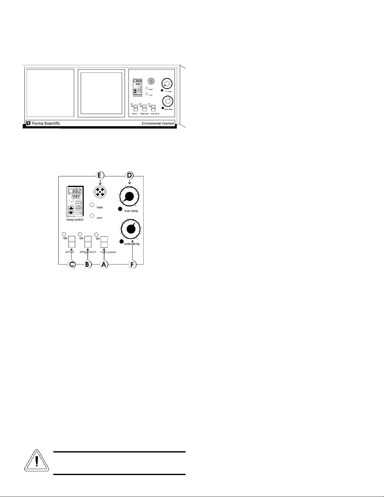
Figure 3-1
Model 3920 Control panel
3.1 The 3920 Control Panel
Figure 3-2
AMain Power Switch and Indicator Light (Figure 3-2)
The main power switch controls power to the incubator.
The main power indicator lights when the power switch is on
and the unit is receiving power.
BRefrigeration Switch and Indicator Light (Figure 3-2)
The refrigeration switch controls power to the refrigeration
system. The refrigeration indicator lights when the refrigeration
switch is on and the compressor is receiving power.
CDefrost Switch and Indicator Light (Figure 3-2)
The defrost switch controls power to the defrost system.
The defrost timer is factory set to provide (2) 15-minute defrost
cycles during a twenty-four hour period. The defrost indicator
lights when the defrost switch is on and the incubator is in
defrost cycle.
The defrost switch must be turned on when the
temperature setpoint is 10°C, or below.
DOvertemp Safety Control, Indicator Light, and
Audible Alarm (Figure 3-2)
The overtemp safety thermostat should be set slightly
above the operating temperature of the incubator. In the event
of an overtemp condition, the overtemp safety thermostat will:
• Activate the audible alarm and the overtemp indicator
light.
• Interrupt power to the heaters and maintain the incubator’s
cabinet temperature at the overtemp safety control point.
Note: The overtemp control is not directly calibrated. The
numbers (0 to 10) on the dial are for reference only and do not
correspond to any specific temperature.
If an overtemp condition occurs, the cause of the problem
must be determined and corrected before normal operation
under the main temperature controller is resumed.
EUndertemp Safety Control, Indicator Light, and
Audible Alarm (Figure 3-2)
FThe undertemp safety thermostat should be set slightly
lower than the operating temperature of the incubator.
In the event of an undertemp condition, the undertemp safety
thermostat will:
• Activate the audible alarm and the undertemp indicator
light.
• Interrupt power to the refrigeration system and maintain
the incubator’s cabinet temperature at the undertemp safety
control point.
Note: The undertemp control is not directly calibrated. The
numbers (0 to 10) on the dial are for reference only and do not
correspond to any specific temperature.
If an undertemp condition occurs, the cause of the problem
must be determined and corrected before normal operation
under the main temperature controller is resumed.
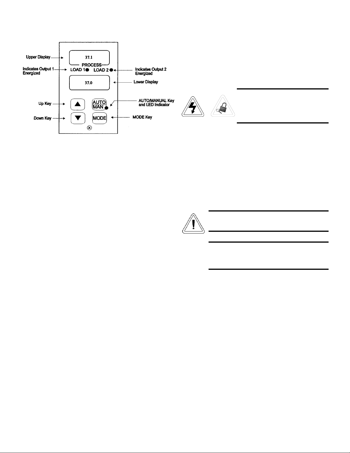
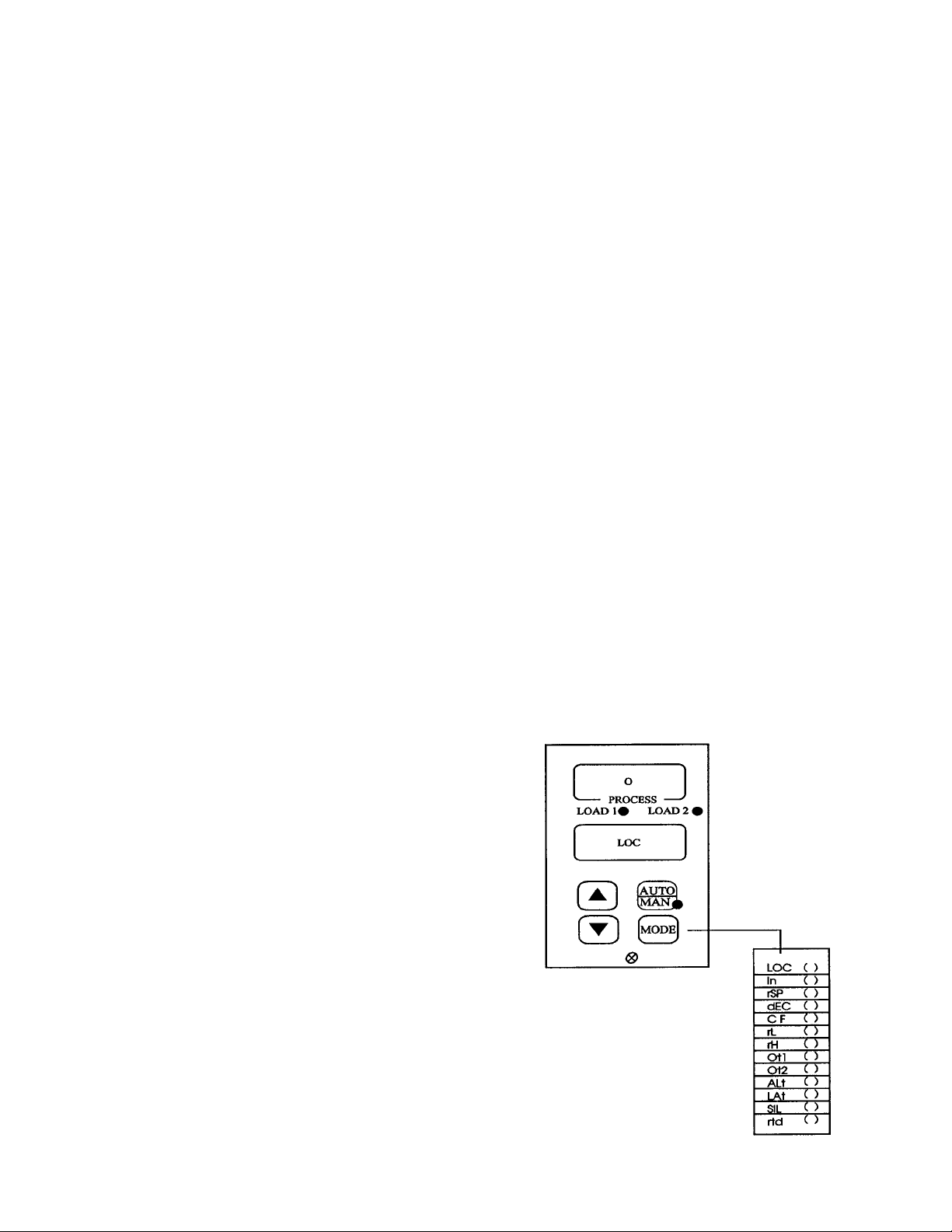
3.2 Temperature Controller (Figure 3-3)
The microprocessor-based controller controls the tempera-
ture function of the incubator.
The controller has been factory-configured with LOC 2
level of operator lock-out to operate in the AUTO mode only.
This lock-out level permits setpoint adjustment only. Use the up
and down arrow keys to set the desired temperature and humid-
ity values. Use Figure 3-3 to become familiar with the micro-
processor controller and keypad function.
Model 3920 ___________________________________________________________________Routine Maintenance
4 - 1
Figure 3-3
Microprocessor Controller
UP/DOWN Keys: When both keys are pressed simultane-
ously for 3 seconds, the Setup Menu appears displaying the
LOC parameter. Press both keys again and the Calibration
Menu appears.
UP Key: Press to increase the value by one. Press and hold
to increase the value rapidly.
DOWN Key: Press to decrease the value by one. Press and
hold to decrease the value rapidly.
AUTO/MAN Key: Press once to clear an alarm. Press the
key twice within 5 seconds and the controller toggles between
the auto and manual operation. When in Manual mode, percent
power is displayed in the lower display.
Note: Manual operation has been locked-out on this applica-
tion.
AUTO/MANUAL LED: The LED lights when the control
is in manual operation. The LED blinks to indicate that the con-
troller is toggling between auto and manual operation. After
five seconds without pressing the Auto/Manual key, the LED
stops blinking and returns to its previous state.
Section 4 - Routine Maintenance
4.1 Cleaning the Incubator
De-energize all potential sources of
energy to this unit and lockout/tagout
their controls. (O.S.H.A. Regulation,
Section 1910-147.)
The continued cleanliness of the stainless steel used in
Forma products has a direct effect on the appearance and opera-
tion of the unit. Use the mildest cleaning procedure that will do
the job effectively. Clean the outside of the incubator with soap
and water or with any non-abrasive commercial spray cleaner.
Clean the inside of the chamber with alcohol and/or soap and
water. Disinfect the interior panels with a general use laboratory
disinfectant, diluted according to the manufacturer’s instruc-
tions. rinse the surface thoroughly after each cleaning and wipe
the surfaces dry. Always rub in the direction of the finish pol-
ish lines.
Do not use chlorinated solvents on stainless steel
as they can cause rusting and pitting.
Do not use volatile or aromatic solvents for clean-
ing inside the cabinet as their residue can contam-
inate the cabinet environment.
The Thermopane glass door may be cleaned with commer-
cial glass cleaner or with a solution of ammonia and water.
5.3 Replacing the Optional Recorder and Probe(s)
1. Open the incubator door, and locate the probe mounting
plate attached to the center of the right interior wall.
Remove the mounting plate.
2. Single pen recorders have only one long stainless steel
probe, attached to the lower end of the back of the
mounting plate. Remove the probe by carefully sliding it
out of the housing.
IMPORTANT! Use extreme care when installing the new
recorder to avoid severely bending the probe capillary tubes.
Dual pen recorders have the stainless steel probe plus a wet
bulb probe attached to the back of the mounting plate. Remove
the screws securing the mounting plate and slide the wet bulb
probe out of its housing.
3. Remove the screws securing the ceiling of the incubator
and remove the ceiling.
4. Remove the top three screws on both edges of the right
duct sheet.
5. Lean the duct sheet out in order to remove the
Permagum seal from around the probe access hole.
6. Open the control panel door, and remove any Permagum
from around the access hole.
7. Pull the probe(s) carefully up through the hole.
8. Follow the probe cable(s) to the back of the recorder,
and carefully clip any plastic ties holding the cable(s) to
other wiring.
9. Remove the three screws securing the recorder and pull
it carefully out from the front of the control panel.
10. Replace the recorder with the correct Forma part.
Note: When replacing the recorder and probe(s), retie the
probe cable(s) to the existing wires.
IMPORTANT! Use extreme care when the new recorder to
avoid severely bending the probe capillary tubes.
5.4 Removing the Top Section
If it becomes necessary to remove the top of the incubator
for moving it through low doorways, use the following proce-
dure:
• Read the instructions completely before starting the
removal process.
• Provide adequate space and sufficient lighting to perform
the work.
• Disconnect the inlet water supply and the drain.
• Before lifting the top section from the incubator, provide
carpenter’s horses or another suitable support arrangement
so that the underside of the top is suspended.
Section 5 - Service
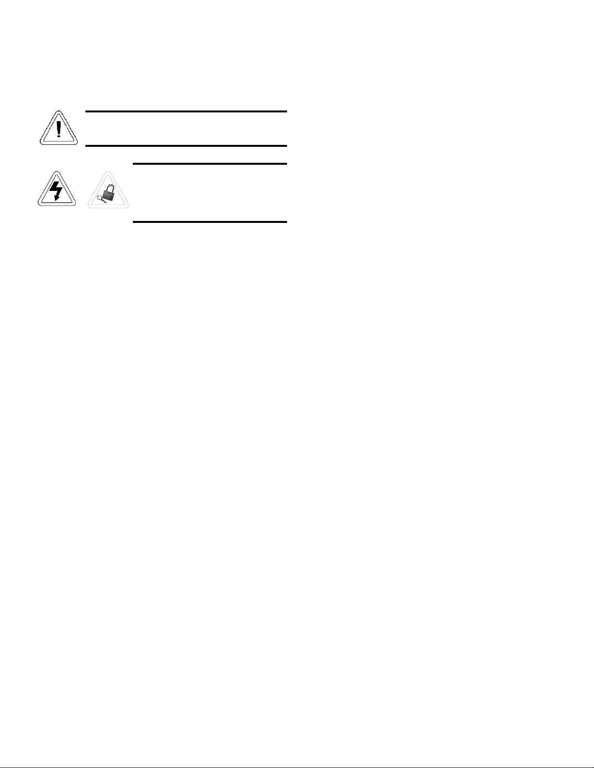
Servicing must be performed by qualified service
personnel only!
De-energize all potential sources of
energy to this unit and lockout/tagout
their controls. (O.S.H.A. Regulation,
Section 1910-147.)
5.1 Access to the Electrical Components
To gain access to the electrical components, open the con-
trol panel and grasp the left side of the control panel housing.
Pull gently, but firmly, up and out.
5.2 Replacing the Overtemp/Undertemp Probe and
Thermostat
1. Remove the incubator ceiling by remove the screws
holding it in place.
2. Remove the top three screws from the top of the right
duct cover.
3. Lean the duct sheet out, and remove the Permagum seal
from around the probe access hole.
4. Remove the two plastic clips that hold the probe in place
and remove the probe.
5. Open the control panel.
6. Pull the overtemp probe up through the access hole and
into the control panel.
7. Follow the wires from the probe to the thermostat
mounted on the control panel. Clip the plastic ties hold-
ing the overtemp cable to the existing wiring.
8. Pull the overtemp knob on the control panel off.
9. Remove the two screws that hold the overtemp assembly
to the control panel.
10. Disconnect the two wires from the back of the thermo-
stat assembly.
11. Pull the entire assembly out of the panel, and remove the
unit.
12. Replace the thermostat and probe.
Note: Reseal the probe access hole with Permagum, and retie
the overtemp cable to the existing wires after replacing the
probe.
Model 3920 _______________________________________________________________________________Service
5 - 1
12. Reinstall the top assembly by reversing the above proce-
dure. Exercise care particularly when:
• Placing and aligning the sealer gasket on the 1/2” flange
on top of the chamber when lowering the top in place.
• Routing the temperature and/or humidity sensors and
capillaries to prevent severely bending them.
• Mounting the temperature and/or humidity sensor bulbs
on the mounting brackets.
• Tightening the top mounting bolts alternately, to ensure a
balanced pressure on the gasket.
5.5 Calibration Offset (Figure 5-1)
It may become necessary to calibrate the temperature offset
to match an independent thermometer. The controller must first
be changed from operator Lock-Out level 2, as it was config-
ured from the factory, to Lock-Out level 0.
The Setup Menu displays the parameters that configure the
microprocessor features to the user's application.
To enter the Setup Menu press the UP and DOWN keys
simultaneously for three seconds. The Lower Display shows the
LOG parameter and the Upper Display shows its current level.
All keys are inactive until the keys are released.
Scroll through the menu using the MODE key and select
Setup data using the UP/DOWN keys. Depending upon the
controller's model number and configuration, some parameters
may not appear on the menu. After scrolling through the menu,
the controller will return to the control setpoint parameter under
the Operation Menu.
Procedure:
1. Remove all test material from the incubator chamber.
2. All temperature-sensing probes are mounted on a probe-
mounting bracket on the right side of the incubator
chamber. Remove the nuts securing the bracket and
then remove the probes from the bracket. Note the loca-
tion and configuration of the probes.
3. The sensing bulb capillaries are routed behind the duct
sheet, up to the access port at the top of the unit and
behind the control panel.
Note: Route all the probes between the duct sheet and the out-
side wall of the chamber so that when the top is raised, all
probes will move freely up and out. Do not kink or bend the
capillaries.
4. The humidification system drain line (3/8” clear tygon)
is routed down through the access port and is secured to
the condensate drain tube on the center left side of the
incubator (as viewed from the rear). Free the drain line
by pulling it away from the float tank (behind the con-
trol panel) and routing it down through the access port.
5. Open the control panel (up to 90°) by grasping the left
side and pulling out until the catch releases.
6. Loosen the top gasket around each of the air exhaust
vents by turning the screw.
7. Remove the eight screws from the top cover of the incu-
bator.
8. Remove the four screws from each of the vent caps on
the top cover of the incubator. The top cover can now be
removed.
9. Remove the nine 5/16” x 4” hex head bolts, lock wash-
ers, and two flat washers which secure the top assembly
to the cabinet. Note the washer arrangement on the
bolts.
10. Remove the black trim gasket located at the junction of
the top assembly and the main incubator section. The
ends of the gasket have been joined together at the rear
of the incubator.
Note: When raising the top section, note the orientation of the
gasket seal at the top opening of the incubator chamber. The
gasket must be correctly positioned when reinstalling the top on
the chamber.
11. Slowly lift the entire top assembly up and off the lower
chamber section while carefully guiding the capillaries
and sensing bulbs out of the chamber area. Place the top
assembly onto the carpenter’s horses or other support
arrangement.
Model 3920 _______________________________________________________________________________Service
5 - 2
Figure 5-1

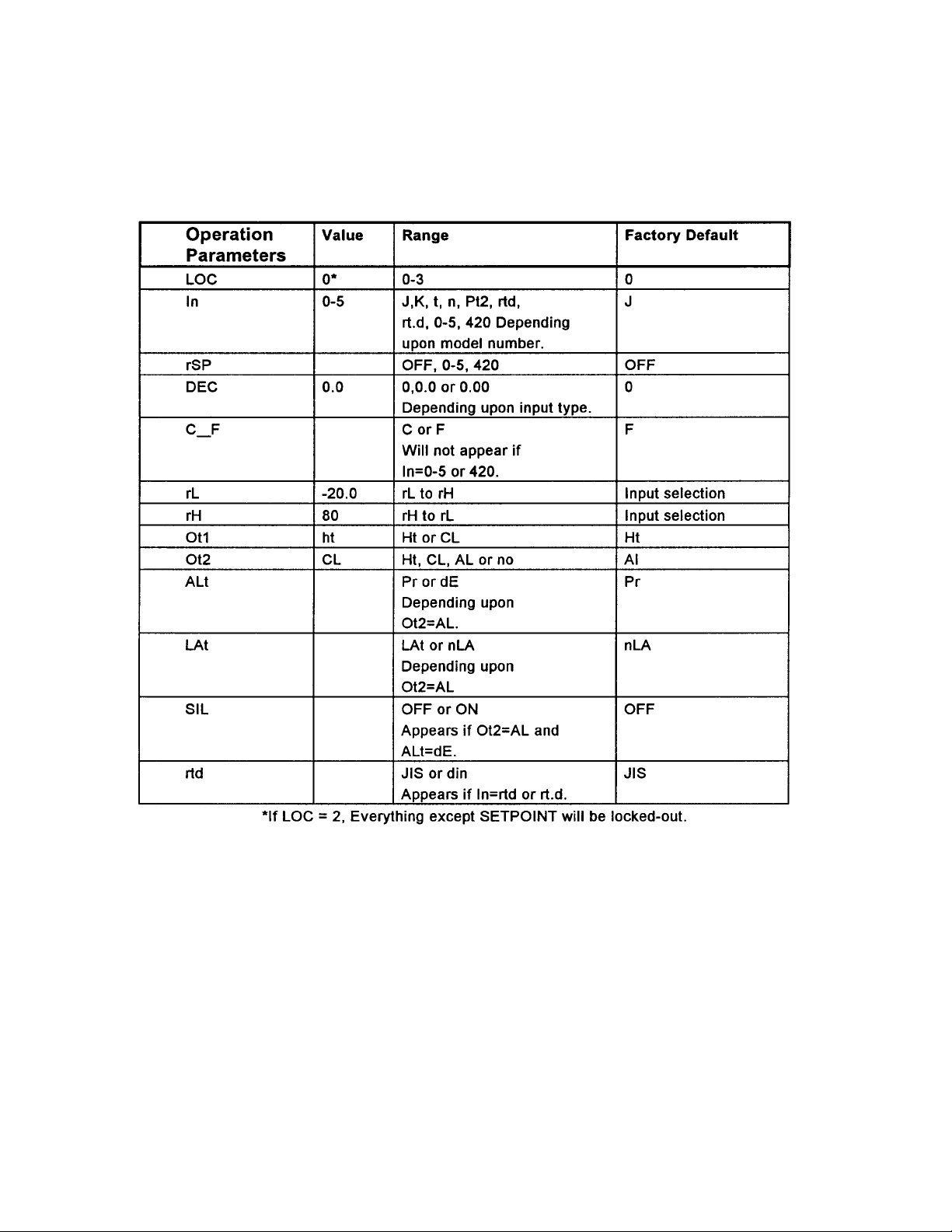
Set-Up Parameters
At the top of the menu, the controller displays the user
level of operation in the Upper display, and LOG parameter in
the Lower display. When pressing the MODE key, the value of
the next parameter appears in the Upper display, and the param-
eter itself in the Lower display.
LOCK: Selects the level of operator lock-out. This parameter's
range is from 0-3. The factory default is 2. The levels of
operator lock-out are defined as follows:
LOC 0: All operating parameters may be viewed or changed.
Manual operation is permitted.
LOC 1: The setpoint and actual are the only visible parameters
the setpoint is adjustable in this level of lock-out. Manual
operation is permitted.
LOC 2: The setpoint and actual are the only visible parameters,
the setpoint is adjustable in this level of lock-out. Manual
operation is not permitted. Bumpless transfer is defeated.
LOC 3: The setpoint and actual are the only visible parameters,
the setpoint is not adjustable in this level of lock-out.
Manual operation is not permitted. Bumpless transfer is
defeated.
Note: Select the "LOG 0" level to change the CALIBRATION
OFFSET parameter. Press the "MODE" key to cycle through
the menu until "CAL" appears in the display.
The Calibration Offset range is from ±55°C. The default is
0°C Calibration Offset adds or subtracts degrees from the input
signal. Match the Calibration Offset displayed value with the
independent test instrument value.
5.6 Controller Configuration
The controller has been pre-configured at the factory. A ref-
erence copy of the Temperature Configuration record is includ-
ed with the manual.
The controller should not be re-configured with-
out first consulting Forma Scientific, Inc., Service
Department at 1-800-848-3080.
Model 3920 _______________________________________________________________________________Service
5 - 3

Model 3920 _______________________________________________________________________________Service
5 - 4
Temperature Configuration
11/18/92
Rev. 2
Model 3920 _______________________________________________________________________________Service
5 - 5
Temperature Configuration (continued)

5.7 Handling Error Codes on the Microprocessor
Note: Microprocessor errors may originate from the follow-
ing conditions:
• Electrical noise
• A noise event
• Excess environmental moisture
• Excess environmental temperature
If error cause is not otherwise apparent, check for the following
listed below.
• Three dashes, "---", in the upper display indicates a micro-
processor error.
If operator access is LOC 0 or 1:
• Press the AUTO/MAN key twice to see the error code for
one second.
If operator access is LOC 2 or 3:
• The error code is already in the lower display. Listed below
are the error code definitions and actions.
Er 1 - Sensor overrange error
The sensor input is generating a value that is higher than
that allowed for the range of this sensor, or the A/D circuit-
ry is not functioning properly.
Enter a valid input.
Er 2 - Sensor underrange error
The sensor input is generating a value that is lower than
that allowed for the range of this sensor, or the A/D circuit-
ry is not functioning properly.
Enter a valid input.
Er 3 - Ambient error
Check the specification for the ambient temperature range.
Er 4 - Configuration error
The unit's microprocessor is faulty; call the factory.
Er 5 - Non volatile checksum error
The nonvolatile memory checksum has discovered a check-
sum error. Unless a momentary power interruption
occurred while the unit was storing data, the nonvolatile
memory is bad. Call the factory.
Er 7 - A/D overflow error
The A/D circuit is over-or under-range. An open or
reversed polarity sensor is the most likely cause. Check the
sensor; if it is connected and functioning properly, then call
the factory.
To clear a corrected error:
Cycle power to the control. (Turn the main power switch
Off and back to ON).
Model 3920 _______________________________________________________________________________Service
5 - 6

Section 6 – Specifications
Temperature
Control ±0.3°C @ +25°C to +37°C
Range 0°C (32°F) to +60°C (140°F)
Sensor RTD
Controller Digital electronic proportional
Setpoint Digital
Display Digital LED
Readability 0.1°C
Setability 0.1°C
Uniformity ±0.3°C at 25°C to 37°C with
six shelves installed*
Shelves
Standard 6
Maximum 19
Dimensions 30.62”W x 25.81”F-B
(77.78 cm x 65.56 cm)
Construction Solid stainless steel reinforced
Surface Area 5.4 sq. ft. (0.51 sq. m) per shelf
Max. Per Chamber 104.3 sq. ft. (9.69 sq. m)
Clearance Adjustable on 3” (7.62 cm)
centers
Loading 35 lbs. (16 kg) (slide in and out)
50 lbs. (23 kg) (stationary)
Construction
Volume 29 cu. ft. (823 liters)
Interior 304 2B stainless steel
Exterior Cold rolled steel
Insulation 2” (5.1cm) Foamed urethane
Outer Door Gasket Four sided vinyl compression
Finish Powder coated. Salt spray tests
exceed 1000 hrs. per ASTM
Standard B117-85.
Weights
Net 700 lbs.
Shipping
Motor 850 lbs.
Temperature Alarm
Sensor Thermostat
Controller Thermostat
Setpoint Analog reference dial
Alarm Audible/visual
Fittings
Drain Port 3/8” OD Copper
Unit Heat Load
115V 5500 BTUH (1600W)
220V 6000 BTUH (1750W)
Refrigeration
Compressor 1/4 Horsepower, air-cooled
R-134A
Electrical
120V, 1 PH, 2W, 60Hz, 16 FLA
Power Switch 1 Pole
Line Cord None (lockable disconnect
provided)
Dimensions
Exterior 38.0”W x 87.5”H x 32.0”F-B
(96.5cm x 222.3cm x 81.3cm)
Interior 31.0”W x 60.0”H x 27.0”F-B
(78.7cm x 152.4cm x 68.6cm)
Continuing research and improvements may result in specification
changes at any time. Performance plus or minus the least significant
digit unless otherwise specified.
* Better than ±0.5°C uniformity at all other temperature parameters.
Model 3920 _________________________________________________________________________Specifications
6 - 1

Section 7 - Parts List
Stock No. Description Quantity
116000 Dec. Door Hinge, Top RH-RHS 1
116001 Dec. Door Hinge, Bottom RH-RHS 1
245215 Temperature Probe/Digital Control 1
250078 Delay Relay 3-300 Seconds 115V 1
250190 Contactor 2 Pole 25A 1 1
255068 SPDT Designer Toggle Switch 1
260116 Temperature Control Triac/Digital 1
270010 Thermostat B-10 Lo-Temp, Adjustable 1
275081 0.1 MFD 400WVDC Tant. Capacitor 1
285020 Sonalert, 110VAC, 2.9kHz 1
285422 15A 400PIV Triac 1
1211101 100, 5W, 10% Carbon Resistor 1
285476 Digital Thumbwheel Switch 0 to 69.9°C 1
285606 Design Toggle Switch SPST 2
285660 2-1/4 Blue Knob w/Clear Skirt 1
290113 5/16 Neon Pilot 115V Red 5
940235 2" Dial Thermometer 1
420400 3900 Door 36 x 65 Mag. Gasket 1
Other parts may be available specific to each job.
Model 3920 ___________________________________________________________________________Parts List
7 - 1
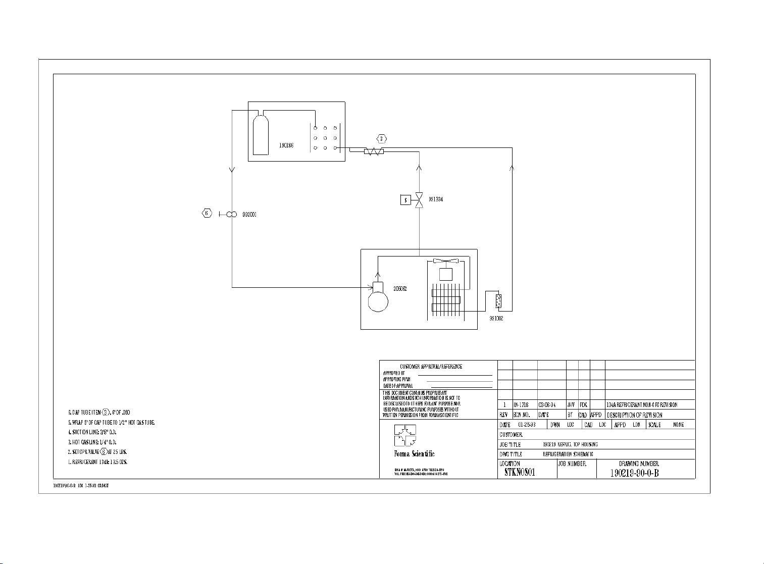
Model 3920 _________________________________________________________________Refrigeration Schematic
8 - 1

Model 3920 ____________________________________________________________________Electrical Schematics
8 - 2
Other manuals for 3920
2
Table of contents
Other Forma Scientific Accessories manuals

Forma Scientific
Forma Scientific 3158 User manual

Forma Scientific
Forma Scientific 3546 User manual

Forma Scientific
Forma Scientific 3950 User manual

Forma Scientific
Forma Scientific 3980 User manual

Forma Scientific
Forma Scientific 3980 User manual

Forma Scientific
Forma Scientific 3940 User manual

Forma Scientific
Forma Scientific 3911 Operating instructions

Forma Scientific
Forma Scientific 3250 User manual

Forma Scientific
Forma Scientific 310 Series Operating instructions

Forma Scientific
Forma Scientific 3158 User manual


