Forma Scientific 3911 Operating instructions

Models 3911 and 3913
Reach-In Incubator
11 cu. ft. capacity
Operating and Maintenance Manual
Manual No: 7013911 Rev. 9
Forma Scientific, Inc.

Forma® Model 3911/3913 ___________________________________________________________________________
i
Read This Instruction Manual.
Failure to read, understand and follow the instructions in
this manual may result in damage to the unit, injury to operat-
ing personnel, and poor equipment performance.
CAUTION! All internal adjustments and maintenance must
be performed by qualified service personnel.
Refer to the serial tag on the back of this manual.
The material in this manual is for information purposes only.
The contents and the product it describes are subject to change
without notice. Forma Scientific, Inc. makes no representations
or warranties with respect to this manual. In no event shall Forma
Scientific, Inc. be held liable for any damages, direct or inciden-
tal, arising out of or related to the use of this manual.
MANUAL NUMBER 7013911
-- -- 10/11/00 Rev 6 corrections, SIL3 ON Humidity configs, ItemJ L3 off ccs
919187/IN-2816 7/24/00 Added line cord standard ccs
818153/IN-2816 6/27/00 Revise specs and electrical schematics “
-- 19207/IN-2827 “ “ ccs
7-- 6/1/00 Quark format ccs
618972/IN-2791 3/6/00 Updated humidity configs, clarified dehumidify indicator operation ccs
-- -- 12/15/99 Added vent caps ccs
REV ECR/ECN DATE DESCRIPTION By
Contains Parts and Assemblies
Susceptible to Damage by
Electrostatic Discharge (ESD)
CAUTION

Forma® Model 3911/3913 ___________________________________________________________________________
ii
Important operating and/or maintenance instructions. Read the accompanying text carefully.
Ce symbole attire l'attention de l'utilisateur sur des instructions importantes de fonctionnement et/ou d'entretien. Il
peut être utilisé seul ou avec d'autres symboles de sécurité. Lire attentivement le texte d'accompagnement.
Wichtige Betriebs- und/oder Wartungshinweise. Lesen Sie den nachfolgenden Text sorgfältig.
Importante instruccions de operacion y/o mantenimiento. Lea el texto acompanante cuidadosamente.
Potential electrical hazards. Only qualified persons should perform procedures associated with this symbol.
Ce symbole attire l'attention de l'utilisateur sur des risques électriques potentiels. Seules des personnes qualifiées
doivent appliquer les instructions et les procédures associées à ce symbole.
Gefahr von Stromschlägen. Nur qualifizierte Personen sollten die Tätigkeiten ausführen, die mit diesem Symbol beze-
ichnet sind.
Potencial de riesgos electricos. Solo personas das capacitadadas deben ejecutar los procedimientos asociadas con este
simbulo.
Equipment being maintained or serviced must be turned off and locked off to prevent possible injury.
Risques potentiels liés à l'énergie. L'équipement en entretien ou en maintenance doit être éteint et mis sous clé pour
éviter des blessures possibles.
Geräte, an denen Wartungs- oder Servicearbeiten durchgeführt werden, müssen abgeschaltet und abgeschlossen wer-
den, um Verletzungen zu vermeiden.
El equipo recibiendo servicio o mantenimiento debe ser apagado y segurado para prevenir danos.
Hot surface(s) present which may cause burns to unprotected skin, or to materials which may be damaged by elevated
temperatures.
Présence de surface(s) chaude(s) pouvant causer des brûlures sur la peau non protégée, ou sur des matières pouvant
être endommagées par des températures élevées.
Heiße Oberfläche(n) können ungeschützter Haut Verbrennungen zufügen oder Schäden an Materialien verursachen,
die nicht hitzebeständig sind.
Superficias calientes que pueden causar quemaduras a piel sin proteccion o a materiales que pueden estar danados
por elevadas temperaturas.
√ Always use the proper protective equipment (clothing, gloves, goggles, etc.)
√ Always dissipate extreme cold or heat and wear protective clothing.
√ Always follow good hygiene practices.
√ Each individual is responsible for his or her own safety.

Forma® Model 3911/3913 ___________________________________________________________________________
iii
Do You Need Information or Assistance on Forma Scientific
Products?
do, please contact us 8:00 a.m. to 7:00 p.m. (Eastern Time) at:
1-740-373-4763 Direct
1-888-213-1790 Toll Free, U.S. and Canada
1-740-373-4189 FAX
http://www.forma.com Internet Worldwide Web Home Page
fservice@forma.com Service E-MailAddress
If you
Our staff can provide information on pricing and give you quotations. We
can take your order and provide delivery information on major equipment items or make
arrangements to have your local sales representative contact you. Our products are listed on the
Internet and we can be contacted through our Internet home page.
Our staff can supply technical information about proper setup,
operation or troubleshooting of your equipment. We can fill your needs for spare or replacement
parts or provide you with on-site service. We can also provide you with a quotation on our
Extended Warranty for your Forma products.
Whatever Forma products you need or use, we will be happy to discuss your
applications. If you are experiencing technical problems, working together, we will help you
locate the problem and, chances are, correct it yourself...over the telephone without a service
call.
When more extensive service is necessary, we will assist you with direct factory trained
technicians or a qualified service organization for on-the-spot repair. If your service need is
covered by the warranty, we will arrange for the unit to be repaired at our expense and to your
satisfaction.
Regardless of your needs, our professional telephone technicians are available to assist
you Monday through Friday from 8:00 a.m. to 7:00 p.m. Eastern Time. Please contact us by
telephone or fax. If you wish to write, our mailing address is:
Forma Scientific, Inc.
Millcreek Road, PO Box 649
Marietta, OH 45750
International customers please contact your local Forma Scientific distributor.
Sales Support
Service Support

Table of Contents
Section 1 - Receiving . . . . . . . . . . . . . . . . . . . . . . . . . . .2 - 1
1.1 Preliminary Inspection . . . . . . . . . . . . . . . . . . . . . .2 - 1
1.2 Visible Loss or Damage . . . . . . . . . . . . . . . . . . . . .2 - 1
1.3 Responsibility for Shipping Damage . . . . . . . . . . .2 - 1
Section 2 - Installation and Set-Up . . . . . . . . . . . . . . . . .2 - 1
2.1 Location . . . . . . . . . . . . . . . . . . . . . . . . . . . . . . . . .2 - 1
2.2 Water (Humidity System) and Drain Connections . .2 - 1
a. Connecting Water Inlet for Humidity System . . .2 - 1
b. Alternate Water Supply for Humidity System . . .2 - 1
c. Connecting the Drain Line . . . . . . . . . . . . . . . . .2 - 1
2.3 Remote Data Output . . . . . . . . . . . . . . . . . . . . . . . . .2 - 2
a. RS-232 Data Output . . . . . . . . . . . . . . . . . . . . . .2 - 2
b. Remote Alarm Contacts . . . . . . . . . . . . . . . . . . .2 - 2
2.4 Power Connection . . . . . . . . . . . . . . . . . . . . . . . . . .2 - 2
2.5 Start-Up . . . . . . . . . . . . . . . . . . . . . . . . . . . . . . . . .2 - 3
2.6 Setting the Overtemp Safety Thermostat . . . . . . . . .2 - 3
2.7 Setting the Undertemp Safety Thermostat . . . . . . . .2 - 3
2.8 Preparing the (Optional) CoBex Recorder . . . . . . .2 - 3
a. Installing the Battery . . . . . . . . . . . . . . . . . . . . .2 - 3
b. Changing the Chart Paper . . . . . . . . . . . . . . . . . .2 - 4
c. Changing the Pen . . . . . . . . . . . . . . . . . . . . . . . .2 - 4
d. Calibrating the Chart Recorder . . . . . . . . . . . . . .2 - 4
2.9 Offset Calibration . . . . . . . . . . . . . . . . . . . . . . . . . .2 - 4
2.10 Honeywell Recorder (optional) . . . . . . . . . . . . . . .2 - 5
2.11 Controller Configuration . . . . . . . . . . . . . . . . . . . .2 - 5
Section 3 - Start Up and Operation . . . . . . . . . . . . . . . .3 - 1
3.1 The Control Panel . . . . . . . . . . . . . . . . . . . . . . . . . .3 - 1
3.2 Setting the Incubator’s Operating Temperature . . . . .3 - 2
3.3 Setting the Incubator’s Operating Humidity . . . . . . .3 - 2
3.4 Programming the controllers . . . . . . . . . . . . . . . . . .3 - 2
a. Removing the mechanical lockout . . . . . . . . . . .3 - 3
b. Removing the Software Lockout . . . . . . . . . . . .3 - 3
3.5 Air Exchange Ventilator Caps . . . . . . . . . . . . . . . . .3 - 3
Section 4 - Routine Maintenance . . . . . . . . . . . . . . . . . .4 - 1
4.1 Cleaning the Incubator . . . . . . . . . . . . . . . . . . . . . .4 - 1
a. Maintaining the Humidity Steam Generator . . . . .4 - 1
Section 5 - Service . . . . . . . . . . . . . . . . . . . . . . . . . . . . .5 - 1
5.1 Accessing the Electrical Components . . . . . . . . . . .5 - 1
5.2 Replacing the Over/Undertemp Probe & Thermostat 5 - 1
5.3 Replacing the Humidity/Temperature Sensor . . . . . .5 - 1
5.4 Replacing the Optional Recorder and Probe(s) . . . .5 - 1
5.5 Setting the Door Heater Control . . . . . . . . . . . . . . .5 - 2
5.6 Cleaning and Adjusting Humidity Steam Generator . .5 - 2
a. Checking the Steam Generator Safety Thermostat
Calibration . . . . . . . . . . . . . . . . . . . . . . . . . . . . . . .6 - 1
Section 6 - Specifications . . . . . . . . . . . . . . . . . . . . . . . .6 - 1
Section 7 - Spare Parts . . . . . . . . . . . . . . . . . . . . . . . . . .7 - 1
Section 8 - Refrigeration Schematic . . . . . . . . . . . . . . . .8 - 1
Section 9 - Electrical Schematics . . . . . . . . . . . . . . . . . .9 - 1
Forma® Model 3911/3913 ______________________________________________________________________ Contents
iv

Forma® Model 3911/3913 ____________________________________________________________Installation and Set-Up
Section 2 - Installation and Set-Up
2.1 Location
Locate the unit on a firm, level surface in an area of mini-
mum ambient temperature fluctuation. A minimum of twelve
(12) inches of clearance is required at the top of the incubator
and a minimum of three (3) inches of clearance is required at
the rear of the incubator. This space is necessary to allow ade-
quate air flow around the refrigeration system.
2.2 Water (Humidity System) and Drain Connections
a. Connecting Water Inlet for Humidity System
Do not attempt to operate the humidity system
without filling it with water. The humidification
heater will overheat, and the overtemp safety ther-
mostat will shut the humidification system down.
The humidity reservoir will require approximately one
quart (0.946 liter) of water on the initial filling. For best opera-
tion of the incubator, sterilized distilled, demineralized or de-
ionized water should be used in the humidity reservoir. Water
purity should be in the resistance range of 50K Ohm/cm to 1M
Ohm/cm, or a conductivity range of 20.0 uS/cm to 1.0 uS/cm.
Refer to ASTM Standard D5391-93 or D4195-88 for measuring
water purity.
Distillation systems, as well as some types of reverse
osmosis water purity systems, can produce water in the quality
range specified. Tap water is not recommended as it may con-
tain chlorine, which can deteriorate the stainless steel. Tap
water may also have a high mineral content, which would pro-
duce a build-up of scale in the reservoir. High purity, ultra pure
or milli-q water is not recommended as it is an extremely
aggressive solvent and will deteriorate the stainless steel. High
purity water has a resistance of above 1M Ohm to 18M Ohm.
Even high purity water can contain bacteria and organic con-
taminants. Water should always be sterilized or treated with a
decontaminant, safe for use with stainless steel as well as safe
for the product, prior to being introduced into the humidity
reservoir.
Distilled or de-ionized water used in the humidity
reservoir must be within a water quality resistance
range of 50K Ohm/cm to 1M Ohm/cm to protect
and prolong the life of the stainless steel. Use of
water outside the specified range will decrease the
operating life of the unit and may void warranty.
Section 1 - Receiving
1.1 Preliminary Inspection
This incubator was thoroughly inspected and carefully
packed prior to shipment and all necessary precautions were
taken to ensure its safe arrival. Immediately upon receipt,
before the incubator is moved from the receiving area, carefully
examine the shipment for loss or damage. Unpack the incubator
and inspect its interior and exterior for any in-transit damage.
1.2 Visible Loss or Damage
If any loss or damage is discovered, note any discrepancies
on the delivery receipt. Failure to adequately describe such evi-
dence of loss or damage may result in the carrier refusing to
honor a damage claim. Immediately call the delivering carrier
and request that their representative perform an inspection. Do
not discard any of the packing material and under no circum-
stances move the shipment from the receiving area.
1.3 Responsibility for Shipping Damage
For products shipped F.O.B. Marietta, Ohio, the responsi-
bility of Forma Scientific, Inc. ends when the merchandise is
loaded onto the carrier’s vehicle.
On F.O.B. Destination shipments, Forma Scientific and the
carrier’s responsibility ends when your Receiving Department
personnel sign a free and clear delivery receipt.
Whenever possible, Forma Scientific will assist in settling
claims for loss or in-transit damage.
2 - 1

Forma® Model 3911/3913 ____________________________________________________________Installation and Set-Up
2 - 2
2.3 Remote Data Output
a. RS-232 Data Output
The Model 3911/3913 incubator is equipped with an RS-
232 Serial Communication Interface for the remote transmis-
sion of temperature and humidity data. A terminal strip is locat-
ed on the back of the incubator for convenience. Refer to
Figure 2-2 for terminal pin identification.
b. Remote Alarm Contacts
Remote alarm connections are also included on the termi-
nal strip (Figure 2-2) providing Normally Open (N.O.) and
Normally Closed (N.C.) contacts. C is the Common terminal.
The remote alarm will activate when either the incubator’s tem-
perature or humidity go out of the set alarm limits.
2.4 Power Connection
See the serial tag on the side of the unit for electrical spec-
ifications, or refer to the electrical schematics at the end of this
manual.
Connect the incubator to a grounded, dedicated
circuit. The power cord connector is the mains
disconnect device for the incubator. Position the
incubator so the unit can be easily disconnected.
For Model 3911, plug the provided 10 ft. power cord with
the NEMA 14-20 plug into the power outlet connection on the
back of the cabinet, then into the grounded dedicated electrical
circuit.
For Model 3913, the electrical junction box is located on
the rear top section of the incubator. With the junction box
switch OFF, connect the incubator to an adequate power source.
The water inlet is the 1/8” FPT connection located on the
rear top left corner of the incubator. Water inlet pressure must
not exceed 40 PSI. a manual shut-off valve should be installed
between the main water supply and the incubator.
To prevent mineral buildup on heater coils and
humidity generator walls, it may be necessary to
clean the humidity generator and immersion
heaters with a non-metallic abrasive pad and
flush thoroughly every two to three months. Refer
to Section 5.7, Cleaning and Adjusting the
Humidity Steam Generator.
b. Alternate Water Supply for Humidity System
If an in-house water supply of the required purity range
(50K to 1M Ohm) is not available, an alternate water supply
method can be used. A large vented carboy (5 gal. minimum) of
water in the required purity range can be placed on top of the
unit. Connect it to the 1/8” FPT water inlet fitting, located on
the rear top left corner of the incubator.
IMPORTANT: The maximum water consumption of this incu-
bator could be as high as 2 gallons per day. When using an
alternate water supply method, it is imperative that the humidity
reservoir not be allowed to run dry, as permanent damage to the
steam generator will result.
c. Connecting the Drain Line
The cabinet’s 3/8” MPT drain line connection is located on
the rear (lower left side) of the cabinet. A P-trap (Figure 2-1) is
included with the unit and must be installed on the connection.
To install the drain connection:
1. Using Teflon pipe thread tape, tape the threads on the
cabinet drain connection.
2. Using an open end adjustable wrench, install the P-trap
onto the connection. Make sure that the trap is posi-
tioned down.
3. Push a piece of 3/8” ID tubing onto the trap and direct
the tubing to a convenient drain. Install a hose clamp on
the tubing, if desired.
Figure 2-1
Cabinet drain P-trap
Figure 2-2

Forma® Model 3911/3913 ____________________________________________________________Installation and Set-Up
2 - 3
2.7 Setting the Undertemp Safety Thermostat
Allow the chamber temperature and humidity to stabilize,
then set the undertemp safety thermostat as follows:
1. Turn the undertemp control knob slowly clockwise until
the audible alarm sounds and the undertemp indicator
lights.
2. Turn the undertemp control knob counterclockwise
approximately two units on the scale. The alarm should
be silenced and the undertemp indicator light should go
out.
The undertemp safety thermostat is now set a few degrees
below the control temperature setpoint. When the chamber tem-
perature drops to the undertemp control point, the alarm system
will activate, power to the compressor will shut off, and the
chamber temperature will be maintained at the undertemp con-
trol point.
When an undertemp condition occurs, the cause must be
determined and corrected before normal operation under the
main temperature controller can be resumed.
Note: When the chamber temperature control setpoint is
changed, the undertemp safety thermostat must be reset to
accommodate the change.
2.8 Preparing the (Optional) CoBex Recorder
a. Installing the Battery
The seven-day circular chart recorder is located on the
front of the incubator cabinet and is protected by a glass door.
Figure 2-3
2.5 Start-Up
When the humidification system is operational, the incuba-
tor may be started. Preset the controls as follows:
Overtemp Safety Thermostat . . . . . . . . . . . . Fully Clockwise
Undertemp Safety Thermostat . . . . . . Fully Counterclockwise
Main Power Switch . . . . . . . . . . . . . . . . . . . . . . . . . . . . . .ON
Humidity Controller . . . . . . . . . . . . . . . . . . .Desired Setpoint
Temperature Controller . . . . . . . . . . . . . . . . .Desired Setpoint
Door Heater . . . . . . . . . . . . . . . . . . . . . . . . .40% (factory set)
For best overall performance of the incubator, the refrigera-
tion switch should be turned on for most applications. When
running Low or No humidity at high temperatures, the refriger-
ation switch may be turned off.
The defrost switch must be turned on when the
temperature setpoint is 10°C, or below.
2.6 Setting the Overtemp Safety Thermostat
Allow the chamber temperature and humidity to stabilize
then set the overtemp safety thermostat as follows:
1. Turn the overtemp control knob slowly counterclock-
wise until the audible alarm sounds and the overtemp
indicator lights.
2. Turn the overtemp control knob clockwise approximate-
ly two units on the scale. The alarm should be silenced
and the overtemp indicator light should go out. The
overtemp safety thermostat is now set a few degrees
above the control temperature setpoint.
When the chamber temperature rises to the overtemp con-
trol point, the alarm system will activate, power to the heaters
will shut off, and the chamber temperature will be maintained
at the overtemp control point.
When an overtemp condition occurs, the cause must be
determined and corrected before normal operation under the
main temperature controller can be resumed.
Note: When the chamber temperature control setpoint is
changed, the overtemp safety thermostat must be reset to
accommodate the change.
12
3
timeline
groove
press to
change
chart
slotted screws
(loosen only) 9-voltbattery

Forma® Model 3911/3913 ____________________________________________________________Installation and Set-Up
2 - 4
Note: For 2 pen operations, first select
the pen you wish to calibrate. Hold
down the #1 arrow for the red (#1) pen
or the #2 arrow for the blue (#2) pen,
until the light goes out. Refer to Figure
2-4. Then adjust as necessary.
If an adjustment is necessary, press
either the #1 or #2 button to move the
pen left or right. The button must be
held about five seconds before the pen begins to move. Release
the button when the pen matches the thermometer.
2.9 Offset Calibration
It may be necessary to calibrate the temperature or humidi-
ty controllers to match an independent temperature or humidity
sensor. To do so, follow the next few steps.
1. Suspend an independent, calibrated sensor(s) in the cen-
ter of the interior chamber.
2. Allow approximately 30 minutes for the incubator to
stabilize.
3. Turn off the main power switch.
4. Wear a grounding wrist strap to avoid damaging any of
the electrical components.
Figure 2-5
5. Remove the 982 controller module(s) by pressing in the
four retaining tabs, two on the right side, two on the left
side. Refer to Figure 2-5. Pull the controller module out
by gently rocking it from side to side.
6. Looking at the top
and right side of the
controller module,
locate the red DIP
switches indicated
in Figure 2-6. Use
your fingernail or a
small screwdriver,
to turn off SW 2 by
moving the white
toggle towards the
front of the module
as shown in the
illustration.
To prepare the recorder for operation, open the glass door
and snap the connector onto the 9-volt battery as shown in
Figure 2-3. If the unit is operating, the green LED lights steady.
If the unit is not turned on, the LED blinks.
If the battery is weak or not connected, the green LED will
flash. If power is lost to the cabinet, the LED will also flash.
When replacing the 9-volt battery, use only an alkaline style
battery. Dispose of the old battery following established envi-
ronmental practices.
b. Changing the Chart Paper
1. Press the Change Chart button (#3) and hold it for 1 sec-
ond until the pen begins to move to the left of the chart.
See Figure 2-3.
2. Remove the existing chart by unscrewing the center
knob securing it.
3. Install the new chart, positioning it so that the correct
time line coincides with the time line groove on the
chart plate.
4. Replace the center knob and screw it tightly against the
chart.
c. Changing the Pen
1. Using a small flat blade screwdriver, loosen the 2 screws
holding the pen arm and remove the pen and arm as an
assembly.
2. Unsnap the plastic hinge securing the pen. Remove and
discard the old pen.
3. Install the new pen by snapping the hinge securely
around the pen arm.
4. Re-install the pen assembly by sliding the pen arm under
the screws, positioning the pen tip in the time line
groove. Tighten the screws.
5. Push the Chart Change button and hold it for 1 second
until the pen begins to move back onto the chart.
Note: Make sure that the pen is marking on the chart. It may
be necessary to gently lift the pen onto the chart paper.
d. Calibrating the Chart Recorder
Place an accurate thermometer(s) in the chamber next to
the recorder’s probe(s). After about three minutes, compare the
thermometer with the chart recorder. For 2 pen operations, also
compare the second thermometer.
Press Press
Side View
SW 2
SW 1
ON OFF
Figure 2-4
Figure 2-6

Forma® Model 3911/3913 ____________________________________________________________Installation and Set-Up
2 - 5
7. Return the controller into its frame and firmly press on
the top and bottom of the bezel until all four locking
tabs “click” into place.
8. Turn on the main power switch.
9. Press the Up and Down Arrow keys simultaneously for
3 seconds. The word “InPt” will appear in the upper dis-
play, and “set” will appear in the lower display.
10. Press the Down Arrow once, then continue to press the
Mode key until “LOC” appears in the lower display. The
upper display will show 2. Press the Down Arrow until
0 appears.
11. Press the Mode key once, then the Up Arrow once.
“InPt” will appear in the upper display, and “set” will be
in the lower display. Press the Mode key until “CAL 1”
appears in the lower display. Press the Up or Down
Arrow key to either add or subtract an offset value. This
would be the difference between the actual value shown
on the controller, and the reference sensor value.
12. Press the Display key once.
To turn the hardware lockout back on:
1. Press the Up and Down Arrow keys simultaneously for
3 seconds. The word “InPt” will appear in the upper dis-
play, and “set” will appear in the lower display.
2. Press the Down Arrow once, then continue to press the
Mode key until “LOC” appears in the lower display. The
upper display will show 0. Press the Up Arrow until 2
appears.
3. Press the Display key once.
4. Turn off the main power switch.
5. Wear a grounding wrist strap to avoid damaging any of
the electrical components.
6. Remove the 982 controller module(s) by pressing in the
four retaining tabs, two on the right side, two on the left
side. Pull the controller module out by gently rocking it
from side to side.
7. Looking at the top and right side of the controller mod-
ule, locate the red DIP switches. Use your fingernail or
a small screwdriver, to turn on SW 2 by moving the
white toggle towards the back of the module.
8. Return the controller into its frame and press firmly on
the top and bottom of the bezel until all four locking
tabs “click” into place.
9. Turn on the main power switch.
2.10 Honeywell Recorder (optional)
The Honeywell, DR 4500 Recorder is a one to four-chan-
nel microprocessor-based, circular chart recorder.
The recorder is capable of recording both temperature and
humidity and printing alphanumeric chart data on blank heat-
sensitive chart. Refer to the Honeywell Configuration at the
end of this section and the supplemental Honeywell Recorder
Manual.
2.11 Controller Configuration
The Watlow 982 Temperature and Humidity
Controllers have been configured at the factory. Copies of the
Watlow Configuration records are included on the following
pages.
The controller should not be re-configured with-
out first consulting Forma Scientific Service
department at 1-888-213-1790.
Refer to Section 3 of this manual for operating instructions
for the Watlow controllers. The Watlow factory manuals are
included with this manual.

3911,13 (WATLOW 982) CONFIGURATION RECORD
CUSTOMER:
JOB NUMBER:
UNT SERIAL NUMBER:
CONTROL TYPE: Temperature
PREPARED BY: DATE
COMPLETED BY: DATE
Switch Configuration:
Main Boards
Input 1 Board
Output 3 Option board
SW1
ON
SW1
OFF
Jumper switch setting:
SW2
ON
SW2
OFF
Form B
SW3
ON
Software Configuration:
Operations Menus
SYS:
Ei1S
NA
Ent4
NA
A3LO
-73.3
A4Hi
NA
Ei2S
NA
A2LO
NA
A3Hi
34.0
Aut
OFF
Ent3
NA
A2Hi
NA
A4LO
NA
PID:
Pb1
2.0
dE1
NA
It2
NA
dB
0.0
rE1
0.50
Ct1
5
rA2
0.25
It1
NA
Pb2
1.0
dE2
NA
rA1
0.19
rE2
0.25
Ct2
30
PROG:
See Programming Sheets if required.
Setup Menus
InPt:
In1
RT.D
CAL1
**
rL2
NA
CAL2
NA
dEC1
NA
rtd1
DIN
rH2
NA
Hunt
NA
rL1
-20.0
Ftr1
2
LrnL
NA
rHi
80.0
In2
NA
LrnH
NA
OtPt:
Ot1
Ht
AL2
NA
LAt3
nLA
SIL4
NA
PrC1
NA
LAt2
NA
SIL3
OFF
Aout
NA
HyS1
0.1
SIL2
NA
Ot4
NA
PrC3
NA
Ot2
CL
Ot3
AL3
AL4
NA
ArL
NA
PrC2
NA
AL3
Pr1
HyS4
NA
ArH
NA
HyS2
0.1
HyS3
0.1
LAt4
NA
ACAL
NA
gLbL:
C_F
C
Anun
OFF
PtyP
ti
PStr
StPt
Err
nLA
LoP
-100
gSd
0
LOC
2
*
Ei1
NO
HiP
100
POut
Cont
Ei2
NA
AtSP
90
IdSP
NA
* LOC should be set at 0 until factory testing and calibration is complete.
** This is a calibration factor and will vary from unit to unit.
COM:
bAUd
9600
dAtA
70
PrOt
FULL
Addr
0
IntF
NA
3911CONFIGS.xls PAGE1 REV4 03/30/99
Forma® Model 3911/3913_______________________________________________Configuration Records

3911,13 (WATLOW 982) CONFIGURATION RECORD
CUSTOMER:
JOB NUMBER:
UNT SERIAL NUMBER:
CONTROL TYPE: Humidity
PERPARED BY: DATE:
COMPLETED BY: DATE:
Switch Configuration:
Main Boards
Input 1 Board
Output 3 Option board
SW1
ON
SW1
ON
Jumper switch setting:
SW2
ON
SW2
ON
Form B
SW3
ON
Software Configuration:
Operations Menus
SYS:
Ei1S
NA
Ent4
NA
A3LO
0 *
A4Hi
NA
Ei2S
NA
A2LO
NA
A3Hi
100 *
Aut
OFF
Ent3
NA
A2Hi
NA
A4LO
NA
* These values are customer setable to there alarm points.
PID:
Pb1
8
dE1
NA
It2
NA
dB
0
rE1
0.05
Ct1
5.0
rA2
0.35
It1
NA
Pb2
7
dE2
NA
rA1
0.35
rE2
0.03
Ct2
30
PROG:
See Programming Sheets if required.
Setup Menus
InPt:
In1
0-5
CAL1
**
rL2
NA
CAL2
NA
dEC1
0
rtd1
NA
rH2
NA
Hunt
NA
rL1
0
Ftr1
2
LrnL
NA
rHi
100
In2
NA
LrnH
NA
OtPt:
Ot1
Ht
AL2
NA
LAt3
nLA
SIL4
NA
PrC1
NA
LAt2
NA
SIL3
ON
Aout
NA
HyS1
1
SIL2
NA
Ot4
NA
PrC3
NA
Ot2
CL
Ot3
AL3
AL4
NA
ArL
NA
PrC2
NA
AL3
Pr1
HyS4
NA
ArH
NA
HyS2
1
HyS3
1
LAt4
NA
ACAL
NA
gLbL:
C_F
NA
Anun
ON
PtyP
ti
PStr
StPt
Err
nLA
LoP
-100
gSd
0
LOC
2
*
Ei1
NO
HiP
100
POut
Cont
Ei2
NA
AtSP
90
IdSP
NA
* LOC should be set at 0 until factory testing and calibration is complete.
** This is a calibration factor and will vary from unit to unit.
COM:
bAUd
9600
dAtA
70
PrOt
FULL
Addr
0
IntF
NA
3911CONFIGS.xls PAGE2 REV4 03/30/99
Forma® Model 3911/3913____________________________________________Configuration Records

Forma® Model 3911/3913_____________________________________________________________Start-Up and Operation
3 - 1
Overtemp Safety Control, Indicator Light, and Audible
Alarm (Figure 3-2)
The overtemp safety thermostat should be set
slightly above the operating temperature of the incubator.
In the event of an overtemp condition, the overtemp safety ther-
mostat will:
• Activate the audible alarm and the overtemp indicator
light.
• Interrupt power to the heaters and maintain the incubator’s
cabinet temperature at the overtemp safety control point.
Note: The overtemp control is not directly calibrated. The
numbers (0 to 10) on the dial are for reference only and do not
correspond to any specific temperature.
If an overtemp condition occurs, the alarm can only be
silenced by raising the overtemp safety thermostat setting.
However, the cause of the problem must be determined and cor-
rected before normal operation under the main temperature con-
troller is resumed.
Undertemp Safety Control, Indicator Light and Audible
Alarm (Figure 3-2)
The undertemp safety thermostat should be set
slightly lower than the operating temperature of the
incubator. In the event of an undertemp condition, the
undertemp safety thermostat will:
• Activate the audible alarm and the undertemp indicator
light.
• Interrupt power to the refrigeration system and maintain
the incubator’s cabinet temperature at the undertemp safety
control point.
Note: As with the overtemp safety control, the undertemp con-
trol is not directly calibrated. The numbers (0 to 10) on the dial
are for reference only and do not correspond to any specific
temperature.
If an undertemp condition occurs, the alarm can only be
silenced by lowering the undertemp safety thermostat setting.
However, the cause of the problem must be determined and cor-
rected before normal operation under the main temperature con-
troller is resumed.
Humidify Switch and Indicator
(Figure 3-3)
The humidify switch controls the
power to the humidification system cir-
cuit. The humidity indicator light will cycle as
the controller toggles between humidify and
dehumidify.
Section 3 - Start Up and Operation
Figure 3-1, Reach-In Incubator Control Panel
shown with optional CoBex Recorder
3.1 The Control Panel
Main Power Switch and Indicator Light (Figure 3-2)
The main power switch controls power to the incubator.
The main power indicator lights when the power switch is
on and the unit is receiving power.
Refrigeration Switch and Indicator Light (Figure 3-2)
The refrigeration switch controls power to the refriger-
ation system. The refrigeration indicator lights when the
refrigeration switch is on and the compressor is receiving
power.
Defrost Switch and Indicator Light (Figure 3-2)
The defrost switch controls power to the defrost sys-
tem. The defrost timer is factory set to provide two 15-
minute defrost cycles during a twenty-four hour period.
The defrost indicator lights when the defrost switch is on
and the incubator is in a defrost cycle.
The defrost switch must be turned on when the
temperature setpoint is 10°C, or below.
A
B
C
D
F
Figure 3-2
G
I
H
Figure 3-3
E
Forma® Model 3911/3913_____________________________________________________________Start-Up and Operation
3 - 2
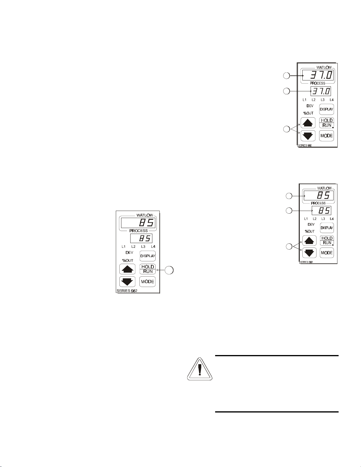
3.2 Setting the Incubator’s Operating Temperature
(Figure 3-5)
The Watlow temperature
controller’s upper numerical
display shows the actual temperature
inside the incubator chamber. The
lower display shows the temperature
setpoint.
Changing the Setpoint
To raise or lower the set-
point, press the up or down
arrow. Temperatures are set in .1°C
increments.
3.3 Setting the Incubator’s Operating Humidity
(Figure 3-6)
The Watlow humidity
controller’s upper numerical
display shows the actual humidity inside
the incubator. The lower display shows
the humidity setpoint.
To raise the setpoint, press the
up or down arrows. Humidity is set
in one percent increments.
3.4 Programming the controllers
The Watlow temperature and humidity controllers have
been set at the factory to operate the incubator within the speci-
fications listed in Section 6 of this manual. Reference copies of
the Watlow configuration records are included at the end of
Section 2 of this manual.
To prevent tampering, mechanical and software lockouts
are employed in the system. These lockouts must only be
removed by persons skilled in configuring controller software.
Making program changes to either the tempera-
ture or humidity controllers will seriously alter the
performance of the incubator and therefore must
be made only by qualified persons. The con-
trollers should not be re-configured without first
consulting Forma Scientific Service Department,
at 1-888-213-1790.
Dehumidify Switch and Indicator (Figure 3-3)
The dehumidify switch will enable the refrigeration
system if the refrigeration switch is currently off. When
controlling humidity, the dehumidification switch should be in
the ON position for most applications. The dehumidification
light will cycle on and off as the humidity controller toggles
between umidify and dehumidify. The dehumidify light will be
de-energized when the system is in Defrost mode.
Humidity is removed from the cabinet by the refrigeration
evaporator coil. Moisture accumulates on the coil and is collect-
ed into the evaporator pan. The accumulated moisture is then
plumbed to the back of the cabinet, which can be emptied to a
floor drain, or an evaporative device.
Audible Humidity Alarm and Indicator Display (Figure 3-3)
The humidity alarm is a function of the humidity con-
troller, Figure 3-4. When the cabinet humidity goes outside
the set parameters of the controller, L3 indicator on the con-
troller lights, the audible alarm sounds, and the humidity alarm
indicator (Figure 3-3, Item I) on the control panel lights.
Hold/Run Key
Pressing the Hold/Run key
(Figure 3-4) on the controller
silences the audible alarm and
extinguishes the humidity alarm indi-
cator and the L3 indicator on the con-
troller. A3HI/A3LO flashes on the
lower display until the cabinet humid-
ity returns to the system setpoint.
Note: The humidity controller’s high
and low limits are set by the factory
at 100% and 0%. Therefore, the sys-
tem will go into the alarm state when
the humidity exceeds these percentages by one percent. When
operating the incubator near these high or low humidity levels,
frequent alarms may occur. This will require that the con-
troller’s high or low limit be reset to three or four percent over
the high limit, or three or four percent under the low limit.
Refer to the Watlow User’s guide provided. Refer also to the
factory configuration records located at the end of Section 2 of
this manual.
I
J
KL
M
H
J
Figure 3-4
K
L
M
Figure 3-5
NO
P
N
O
P
Figure 3-6

Forma® Model 3911/3913_____________________________________________________________Start-Up and Operation
3 - 3
Press the Mode key to scroll through the menus until the
upper and lower displays show “2 Loc” (Figure 3-11). Press the
down arrow key until the 2 becomes 0 (zero) as shown in
Figure 3-12.
Press the Display key to return to showing the setpoint and
actual temperatures. All safeguards are now removed and the
controller may be programmed. Refer to the Watlow publica-
tions included with this operating manual.
Reprogramming the temperature or humidity
controllers will change the factory default
settings and may seriously alter the performance
of the incubator and void the warranty. Contact
the Forma Scientific Service Department, at
1-888-213-1790.
3.5 Air Exchange Ventilator Caps
Air exchange for the incubator is regulated through the
manually adjustable intake and exhaust ventilator caps located
on the top of the cabinet.
When viewed from the front of the incubator, the intake
cap is on the left and the exhaust cap is on the right. The venti-
lator caps may be opened by turning counterclockwise, and
closed by turning clockwise.
For optimum performance of the unit, the vent caps should
be closed at all times.
a. Removing the mechanical lockout
Make sure the unit is turned
off.
Wearing a grounding wrist
strap or maintaining constant con-
tact with the metal cabinet, press
in the four locking tabs on the
frame of the Temperature con-
troller. There are two tabs on
either side as shown in the front
and side views in Figure 3-7.
When all tabs are unlocked, pull
the controller module out of its frame.
Looking at the top of the module, locate the red DIP switch
indicated in Figure 3-8. With a fingernail or small screwdriver,
turn off SW #2 by moving the
white toggle down or towards
the front of the module. (SW#2
is the top switch when looking
at the module from the right
side.)
Very carefully, replace the
module into its frame and press
firmly on the top and bottom of
the bezel until all four locking
tabs “click” into place.
b. Removing the Software Lockout
Press the up arrow and down arrow keys at the same time
and hold them for about three seconds. The words “inpt”
(input) and “set” will appear in the top and bottom displays.
(Figure 3-9) If numbers in the bottom display begin to scroll up
or down, the keys have not been pressed simultaneously. Try
again.
Press the up arrow until “gLbL” (global) appears in the
upper display. The word “set” will remain in the lower display.
(Refer to Figure 3-10)
PressPress
Press
Press Press
Press
Figure 3-7
DIP switch
Top of controller module
SW#1 SW#2
Figure 3-8
Press
(3 sec)
Set
Input
Press
Set
Global
Figure 3-9 Figure 3-10
Press
Lock
2
Press
Change
2 to 0
Figure 3-11 Figure 3-12

Millcreek Road, Box 649 • Marietta, Ohio 45750 USA • 740-373-4763
PREVENTIVE MAINTENANCE
Incubators
Your Thermo Forma equipment has been thoroughly tested and calibrated before shipment. Regular preventive maintenance is
important to keep your unit functioning properly. The operator should perform routine cleaning and maintenance on a regular basis.
For maximum performance and efficiency, it is recommended the unit be checked and calibrated periodically by a qualified service
technician.
The following is a condensed list of preventive maintenance requirements. See the specified section of the instruction manual for
further details.
Thermo Forma has qualified service technicians, using NIST traceable instruments, available in many areas. For more information on
Preventive Maintenance or Extended Warranties, please contact us at the number listed below.
Cleaning and calibration adjustment intervals are dependent upon use, environmental conditions and accuracy required.
Tips for all incubators:
•Do NOT use bleach or any disinfectant that has high chloros
•Use sterile, distilled or demineralized water.
•Avoid spraying cleaner on the CO2sensor.
•Do not use powdered gloves for tissue cultures.

Incubators ______________________________________________________________________________ Preventive Maintenance
Preventive Maintenance for 3911/3920/3940/3980 Series Incubators
Refer to
Manual Section
Action Daily Weekly Yearly
-- Inspect door latch, hinges and door gasket seal. 9
3.5 (3911), 3.4 (3920),
3.5 (3940), 3.17 (3980)
Check the air exchange ventilator caps for adjustment; open or closed as required 9
4.1 Perform a complete decontamination procedure. Wipe down interior, shelves,
side panels with disinfectant. Rinse everything well with sterile distilled water.
Between experiments
More frequent decontamination may be
required, depending on use and
environmental conditions
2.9/3911, 3920 and 3940
or
2.11/3980
* Verify and document all calibrations, at the minimum. 9
5.6/3911 or 5.7/3940
or 5.8/3980
* Inspect and clean the humidity generator, at the minimum 9
-- Clean drip pan and drain lines 9
-- Clean refrigeration system condenser 9
-- Verify defrost cycle for below 10°C operation 9
-- Change filters (under normal conditions) 9
•Qualified service technicians only
•Regular monitoring routines of the various levels in your unit is encouraged.

Forma® Model 3911/3913_______________________________________________________________Routine Maintenance
4 - 1
Section 4 - Routine Maintenance
4.1 Cleaning the Incubator
De-energize all potential sources of energy to this
unit and lockout/tagout their controls. (O.S.H.A.
Regulation, Section 1910-147.)
The continued cleanliness of the stainless steel used in
Forma products has a direct effect on the appearance and opera-
tion of the unit. Use the mildest cleaning procedure that will do
the job effectively. Clean the outside of the incubator with soap
and water or with any non-abrasive commercial spray cleaner.
Clean the inside of the chamber with alcohol and/or soap and
water. Disinfect the interior panels with a general use laboratory
disinfectant, diluted according to the manufacturer’s instruc-
tions. rinse the surface thoroughly after each cleaning and wipe
the surfaces dry. always rub in the direction of the finish polish
lines.
Do not use chlorinated solvents on stainless steel
as they can cause rusting and pitting.
Do not use volatile or aromatic solvents for
cleaning inside the cabinet as their residue can
contaminate the cabinet environment.
The Thermopane glass door may be cleaned with commer-
cial glass cleaner or with a solution of ammonia and water.
a. Maintaining the Humidity Generator
Depending on the quality of water used in the humidifica-
tion system, it may be necessary to clean the humidity genera-
tor and immersion heaters every 2 to 3 months. Refer to Section
5.6 for cleaning instructions.

Forma® Model 3911/3913 _________________________________________________________________________Service
5 - 1
Section 5 - Service
Servicing must be performed by qualified service
personnel only!
De-energize all potential
sources of energy to this
unit and lockout/tagout
their controls.
5.1 Accessing the Electrical Components
To gain access to the electrical components, open the con-
trol panel and grasp the left side of the control panel housing.
Pull it gently but firmly, up and out.
5.2 Replacing the Overtemp/Undertemp Probe and
Thermostat
1. Remove the incubator ceiling by remove the screws
holding it in place.
2. Remove the top three screws from the top of the right
duct cover.
3. Lean the duct sheet out, and remove the Permagum seal
from around the probe access hole.
4. Remove the 15” copper capillary overtemp probe by
extracting the two plastic clips that hold the probe in
place.
5. Open the control panel.
6. Pull the overtemp probe up through the access hole and
into the control panel.
7. Follow the wires from the probe to the thermostat
mounted on the control panel. Clip the plastic ties hold-
ing the overtemp cable to the existing wiring.
8. Pull the overtemp knob on the control panel off.
9. Remove the two screws that hold the overtemp assembly
to the control panel.
10. Disconnect the two wires from the back of the thermo-
stat assembly.
11. Pull the entire assembly out of the panel, and remove the
unit.
12. Replace the thermostat and probe.
Note: Reseal the probe access hole with Permagum and retie
the overtemp cable to the existing wires after replacing the
probe.
5.3 Replacing the Humidity/Temperature Sensor
1. Locate the probe mounting plate in the center of the
right side of the incubator interior.
2. Open the mounting plate by removing the screws that
hold it in place.
3. Locate the humidity sensor mounted on the inside of the
panel in a black housing. Note the angle of the probe.
4. Grasp and unplug the probe from the probe cable.
5. When replacing the humidity sensor, be sure to mount
the probe at the same angle as it was originally mounted.
5.4 Replacing the Optional Recorder and Probe(s)
1. Open the incubator door, and locate the probe mounting
plate attached to the center of the right interior wall.
Remove the mounting plate.
2. The recorder probe is attached to the lower end of the
back of the mounting plate. Remove the probe by care-
fully sliding it out of the housing.
3. Remove the screws securing the ceiling of the incubator
and remove the ceiling.
4. Remove the top three screws on both edges of the right
duct sheet.
5. Lean the duct sheet out in order to remove the
Permagum seal from around the probe access hole.
6. Open the control panel door and remove any Permagum
from around the access hole.
7. Pull the probe(s) carefully up through the hole.
8. Follow the probe cable(s) to the back of the recorder,
and carefully clip any plastic ties holding the cable(s) to
other wiring.
9. Remove the three screws securing the recorder and pull
it carefully out from the front of the control panel.
10. Replace the recorder with the correct Forma part.
Note: When replacing the recorder and probe(s), retie the probe
cable(s) to the existing wires.
Contains Parts and Assemblies
Susceptible to Damage by
Electrostatic Discharge (ESD)
CAUTION

5 - 2
5.5 Setting the Door Heater Control
High voltage is present behind con-
trol panel. Servicing must be per-
formed only by qualified electrical
service personnel.
The infinite heater control is
located in the right side of the incu-
bator top compartment behind the
control panel door. The heater
varies the amount of door heat from
no heat (zero) to full heat (100) as
indicated by the control dial face. If
the knob is turned past zero, a
“click” will indicate that all power
to the door is shut off. If turned past
100, a similar “click” will indicate
that the heat is set at the maximum.
Initially the units leave the factory with the dial set at 40.
If desired, the amount of heat can later be reduced until mois-
ture appears on the door, then the heat advanced. However, in
fluctuating ambient conditions, it is recommended that a mini-
mum of 40% door heat be used.
5.6 Cleaning and Adjusting the Humidity Steam
Generator, P/N 505087
Depending upon the quality of water used in the humidifi-
cation system, it may be necessary to clean the humidity gener-
ator and immersion heaters every 2 to 3 months.
Materials Required: 6-foot stepladder
Flat and Phillips screwdrivers
Clamp-on style Ammeter
Laboratory disinfectant
Siphon, sponge, & cleaning materials
1. Remove all contents from the incubator, shut it off, and
disconnect the power.
2. Turn off the valve supplying the sterile distilled water.
3. From the stepladder, remove the eight Phillips screws
securing the top of the incubator cabinet.
4. When the steam generator has cooled, remove the four
thumbscrews.
The internal temperature of the
steam generator is hot enough to boil
water. Make certain sufficient time is
given to allow the unit to completely
cool before removing the top.
Forma® Model 3911/3913 _________________________________________________________________________Service
5. Lift the top off of the steam generator and lay it to the
side taking care to not crimp the copper capillary tube.
6. Siphon all of the water out of the steam generator and
clean it with a good quality laboratory detergent and dis-
infectant. Do not use any type of chloride cleaner. A
bristle brush may be needed for stubborn rust and scale.
Also clean the inside of the standpipe using a test tube
brush. Siphon and sponge the wash water out of the
boiler. Repeat cleaning with soap and water as neces-
sary.
7. Carefully pry off the brass top of the float control reser-
voir. Clean and disinfect it and the connecting tube
between the reservoir and the steam generator being
careful to not damage the float assembly.
8. Clean the two heater elements and the part of the copper
capillary tube attached to them.
9. When all surfaces are clean, rinse with sterile distilled
water until all soap and disinfectant are removed.
10. Open the distilled water valve and allow the reservoir to
fill. Measure the water level. The limit is three inches,
plus or minus one-quarter of an inch. The water level is
raised and lowered by carefully bending the float arm.
When set, replace the cover.
11. Replace the top of the steam generator and alternately
tighten the four thumbscrews to evenly compress the
rubber gasket.
Figure 5-1
heater
thumbscrew (4)
sterile distilled
water inlet
overflow
float control
reservoir
capillary
tube
blue
wire
heater safety
thermostat
heater
steam
generator
reservoir-steam generator
connecting tube
Figure 5-2
float
valve
float
float
arm
capillary
tube
rubber
gasket
standpipe
Figure 5-3
Other manuals for 3911
5
This manual suits for next models
3
Table of contents
Other Forma Scientific Accessories manuals

Forma Scientific
Forma Scientific 3920 Operating instructions

Forma Scientific
Forma Scientific 3980 User manual

Forma Scientific
Forma Scientific 3158 User manual

Forma Scientific
Forma Scientific 3940 User manual

Forma Scientific
Forma Scientific 3980 User manual

Forma Scientific
Forma Scientific 3940 Operating instructions

Forma Scientific
Forma Scientific 3920 Operating instructions

Forma Scientific
Forma Scientific 3250 User manual

Forma Scientific
Forma Scientific 3158 User manual

Forma Scientific
Forma Scientific 310 Series Operating instructions


