manuals.online logo
Brands
  1. Home
  2. •
  3. Brands
  4. •
  5. Omron
  6. •
  7. Accessories
  8. •
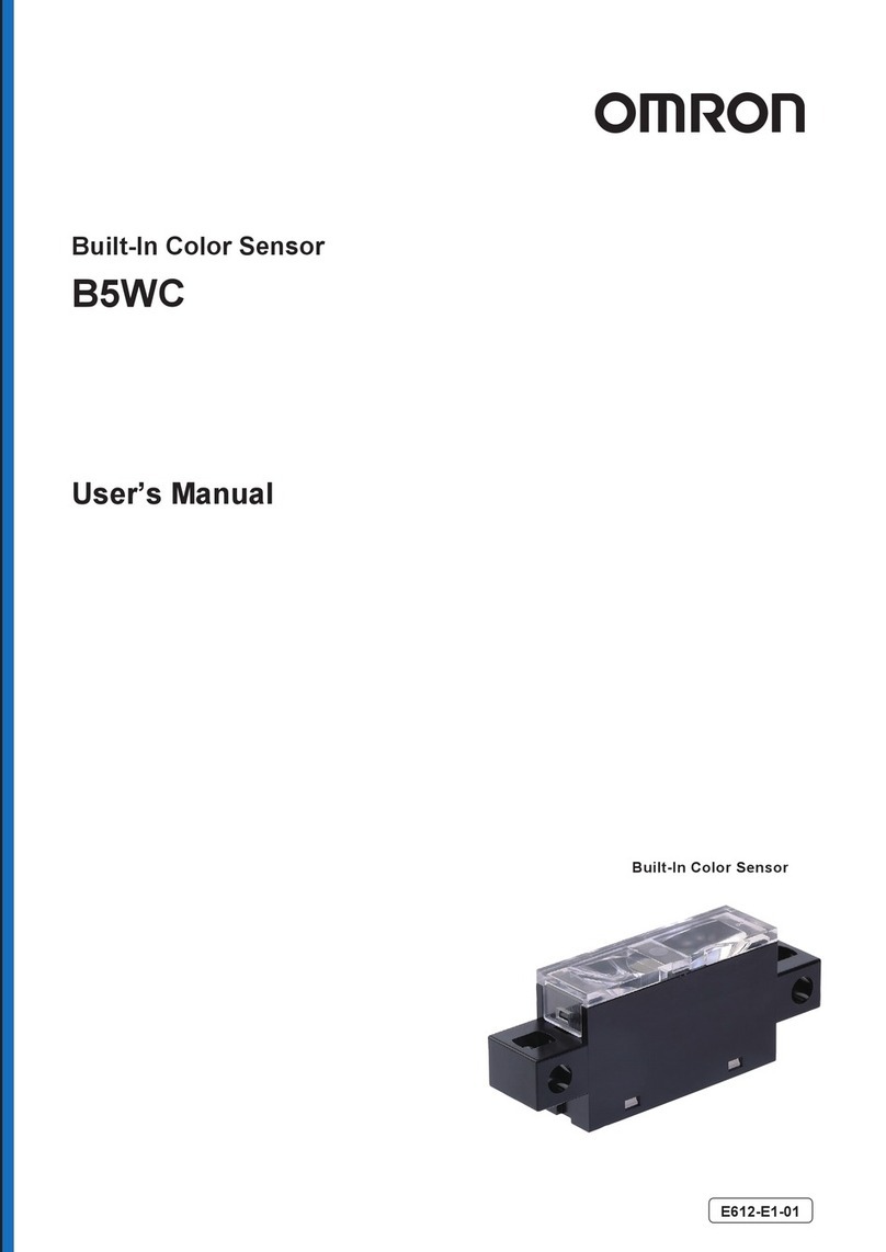
  9. Omron ZFV-CA50 User manual

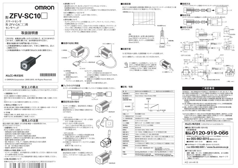
Omron ZFV-CA50 User manual

ZFV-CA50/55
(1/2)
形
ス マ ート セ ン サ 
形ZFV-S□□□用
ア ン プ ユ ニ ット 
以下に示すような項目は安全を確保する上で必要なことですので必ず守ってください。
安全上の要点
使用上の注意
・市販のスイッチングレギュレータをご使用の際は、FG 端子を接地してください。
・電源ラインにサージがある場合、使用環境に応じてサージアブソーバを接続してご使用
ください 。 
■各部の名称と機能
■フェライトコアの装着
■外部入出力
■取付方法
■DIN レールの取付
■DIN レールの取外し
■上位機器との通信について
・ センサ ヘッドや アンプ ユ ニットの 清 掃 に は 、 シンナー 、 ア ルコー ル 、 ベンジン 、 アセトン 、
灯油類は使用しないでください。
・センサヘッド前面のパネルに、大きなゴミやホコリが付いた場合は、ブロアブラシ (カメラ
レンズ用 ) で吹き飛 ばしてください。 呼 気 で吹き飛 ばすことは 避けてください 。 
・小さなゴミやほこりは、柔らかい布で丁寧にふきとってください。強くふくことは避けてく
ださい。キズがつくと、誤検出の原因になります。
・配線後は電源を投入する前に、電源の正誤、負荷短絡などの誤接続の有無、負荷電
流の適否について確認を行ってください。誤配線などで故障するおそれがあります。
・センサヘッドの着脱は、必ず電源を切った状態で行ってください。電源 ON のまま行うと
故障の原因になります。
・センサヘッドとアンプユニットは、取扱説明書で指定した組合せで使用してください。
・液晶ディスプレイパネルは精密な技術で作られておりますが、ごくわずかに画素欠陥が
ある場合があります。これは液晶ディスプレイの構造によるもので故障ではありません。
(1)OUTPUTLED
OUTPUT 信号が ONしたときに点灯します。
(2)RUNLED
RUN モードのときに点灯します。
(3)ERRLED
エラー発生時に点灯します。
(4)READYLED
アンプユニットが正常起動後に点灯します。
(5)操作キー
計測条件など設定するための操作キーです。
(6)メニュー切替えスイッチ
設定メニューを切替えます。
STD…標準メニュー。計測で必要な最低限の項目を設定するときに選択します。
EXP…エキスパートメニュー。より詳細な設定をするときに選択します。
(7)モード切替えスイッチ
操作モードを切替えます。
MENU…計測条件を設定するときに選択します。
ADJ…判定しきい値の調整をするときに選択します。
RUN…通常計測するときに選択します。
(8)液晶モニタ
センサヘッドがら取込んだ画像や設定メニューを表示します。
(9)センサヘッド接続コネクタ
セ ン サ ヘ ッド を 接 続 し ま す 。
(10)連結部
データストレージユニット(形 ZS-DSU□□)を接続するときに使用するコネクタです。
ZFV アンプユニット同士を接続することはできません。
(1)電源
電源を接続します。
電源は高電圧が発生しないように対策 ( 安全超低電圧回路 ) されている直流電
源装置から供給してください。
電源は他の機器とは独立して配線してください。同一配線あるいは同一ダクトに
すると誘導を受け、誤動作あるいは破損の原因となります。
(2)GND
電源用 0V 接続線です。
(3)OUTPUT(制御出力)
判定結果を出力します。OUTPUTLEDと連動しています。
(4)ENABLE(イネーブル出力)
計測可能な場合に ONします。
(5)ERROR(エラー出力)
エラーが発生した場合に ONします。
(6)TEACH(ティーチング入力)
ワーク停 止ティーチングとワーク移 動ティーチングがあり、メニューで選 ぶことができま
す。
(7)TRIG(計測トリガ入力)
同期計測と連続計測があり、どちらの方法で計測するかはメニューで選びます。
(8)BANK1(バンク切替え入力 1)
(9)BANK2(バンク切替え入力 2)
(10)BANK3(バンク切替え入力 3)
3. 設置方向
4. 保守点検について
© OMRON Corporation 2008-2015 All Rights Reserved.
放熱を良くするため、次の方向のみで設置してください。
次のような向きでは設置しないでください。
ア ン プ ユ ニ ット の 入 出 力 コ ー ド に 、 フ ェ ラ イト コ ア 
( アンプユニットの付属品 ) を装着してください。
DINレール(別売)
形 PFP-100N(1m)
形 PFP-50N(0.5m)
形 PFP-100N2(1m)
エンドプレート(別売)
形 PFP-M
OUTPUT
RUN
ERR
READY
DINレールの取付け
35mm 幅の DINレールにワンタッチで取付けることができます。
フ ェ ラ イト コ ア 
1. コネクタ側のツメを DINレールに引っかけます。
2. 入出力コード側のフックがロックされるまで DINレールに押し込みます。
カチッと音がするまで押し込んでください 。 
コネクタ 側 のツメをレール にかけて 取 付けてください 。 入 出 力コード 側 のフックを
レールにかけて取付けると取付け強度が低下します。
1. アンプユニットの入出力コード側のフックを下に引きます。
2. 入出力コード側から持ち上げて、DINレールから外します。
本製品の起動を確認後、上位機器との通信を行ってください。
また、本製品の起動時には、上位インターフェースから不定な信号が出る可能性があります
ので、初期動作時はご使用機器の受信バッファをクリアするなどの処理を実施してください。
コネクタ側 のツメ
入 出 力 コ ード 側 の フ ック 
(1)電源
※RUN モードのみ有効です。
茶
青
黒
橙
水色
黄
桃
灰
緑
赤
紫
白
(2)GND
(3)OUTPUT※
(4)ENABLE
(5)ERROR
(6)TEACH※
(7)TRIG※
(8)BANK1※
(9)BANK2※
(10)BANK3※
未使用
未使用
入力・出力コードの各配線の内容を次に示します。

・引火性、爆発性ガスの環境では使用しないでください。
・操作や保守の安全を確保するため、高電圧機器や動力機器から離して設置してください。
・通風口をふさがないように本体を設置して下さい。
1. 設置環境について
・本体の分解、修理、改造、加圧変形、焼却などは絶対にしないで下さい。
・廃棄するときは、産業廃棄物として処理してください。
3. その他
・定格電圧(DC24V+10%,-15%)を超える電圧や交流電源を使用しないでください。
・電源の逆接続はしないでください。オープンコレクタ出力は、負荷を短絡させないでくださ
い。
・負荷は定格以下で使用してください。
・高圧線、動力線と本製品の配線は別配線としてください。同一配線あるいは同一ダクト
にすると誘導を受け、誤動作あるいは破損の原因になることがあります。
2. 電源および配線について
製品が動作不能、誤動作、または性能・機器への悪影響を防ぐため、以下のことを守っ
てください 。 
次のような場所には設置しないでください。
・周囲温度が定格の範囲を越える場所
・温度変化が急激な場所(結露する場所)
・相対湿度が 35 〜 85%RH の範囲を超える場所
・腐食性ガス、可燃性ガスがある場所塵埃、塩分、鉄粉がある場所
・振動や衝撃が直接加わる場所
・強い外乱光(レーザ光、アーク溶接光など)があたる
・直射日光があたる場所や暖房器具のそば
・水・油・化学薬品の飛沫がある場所
・強磁界、強電界がある場所
1. 設置場所について
2. 電源および接続、配線について
■入出力段回路図
●NPN 出力タイプ ( 形 ZFV-CA50)
●PNP 出力タイプ ( 形 ZFV-CA55)
取扱説明書
このたびは、本製品をお買い上げいただきまして、まことにありがとう
ございます。ご使用に際しては、次の内容をお守りください。
・電気の知識を有する専門家が扱ってください。
・この取扱説明書をよくお読みになり、十分にご理解のうえ、正しく
ご 使 用 くだ さ い 。 
・この取扱説明書はいつでも参照できるように大切に保管ください。
茶
青
黒
橙
水色
負荷
負荷
負荷
電源(DC24V)
OUTPUT
OUTPUT
ENABLE
ERROR
GND(0V)
DC24V
黄
桃
灰
緑
TEACH
TRIG
BANK1
BANK2
赤 BANK3
内部回路
茶
青
黒
橙
水色
負荷
電源(DC24V)
OUTPUT
ENABLE
ERROR
GND(0V)
DC24V
黄
桃
灰
緑
TEACH
TRIG
BANK1
BANK2
赤 BANK3
負荷
負荷
内部回路
(13)入出力コード
(11)RS-232C コネクタ
プログラマ ブ ル コントローラ、 プ ログラマブ ルターミナ ルまた は パソコンと接 続 す
るために、RS-232C ケーブルを接続します。
RS-232C ケーブルは、必ず以下の専用品をご使用ください。専用品以外の
ケーブルを使用した場合、誤動作や故障の原因となります。
[ プログラマブ ルコントローラもしくはプログラマブ ルターミナル 接 続 用 ] 形
ZS-XPT3
[ パソコン接続用 ] 形 ZS-XRS3
(12)USBポート
パソコンと接続するために、USB ケーブルを接続します。
(13)入出力コード
電源および同期センサやプログラマブルコントローラなどの外部装置と接続します。
*4018403- 6D*
(8)液晶モニタ
(1)OUTPUTLED
(2)RUNLED
(3)ERRLED
(4)READYLED
(10)連結部
(11)RS-232Cコネクタ
(12)USBポート
(7)モード切替えスイッチ
(6)メニュー切替えスイッチ
(5)操作キー
(9)センサヘッド接続コネクタ
■外形寸法図
■表示とキー操作
設定は、液晶パネルに表示され
る 画 像 とメニ ューを 見 な がら 、 操
作 キーで 設 定します 。
表示される内容は、
操 作 モードによって 変ります 。
現 在 選んでいるメニューや
計測の種類などが表示されます。
メニューの選択肢や設定項目が
表 示されます 。
選んでいる項目は反転表示されます。
●表示
付属品のラベルをカバー裏面に貼り付けてご使用ください。
●ファンクションキー割付表示ラベルの貼付け
キーの種 類 説 明
← L キー
→ R キー
動 作 モ ード に よ っ て は た ら き が 変 り ま す 。
MENU の場合:メニューの遷移
ADJ の場合:調整項目 (しきい値種類 ) の変更
RUN の場合:表示内容 ( 計測値種類 ) の変更
↑UP キー
↓DOWN キー
動 作 モ ード に よ っ て は た ら き が 変 り ま す 。
MENU の場合:メニューの遷移、パラメータ
       の選択、数値の設定
ADJ の場合:数値の変更
TEACH /
VIEW キー
動 作 モ ード に よ っ て は た ら き が 変 り ま す 。
MENU の場合:ティーチング実行
RUN、ADJ の場合:画面の表示切替え
SET キー
ESC キー
・ メニュー の 選 択
・項目の選択 / 確定
1 つ 前 のメニュー に 戻 ります 。
●キー操作
■定格/性能
項 目
出力仕様
入力仕様
シリアル I/O
検査項目
ティー チング 領 域
ティー チ ング 領 域 サ イズ
検出領域
処理分解能
バンク切 替え
計 測 モ ード
画像入力周期
その他機能
出力信号
入力信号
ヘ ッド イ ン タ フ ェ ー ス
画像表示
表示灯
操 作 インタフェー ス
電源電圧
消費電流
耐電圧
耐ノイズ 性
振動(耐久)
衝撃(耐久)
周囲温度
周囲湿度
周囲雰囲気
保護構造
材質
質量
付属品
全画面
最大 468(H)×432(V)
あり 8 バンク
シングルバンク計測モード /複数バンク計測モード
13ms( 標準 )、8ms(1/2 パーシャルスキャン時 )、5ms(1/4 パーシャルスキャン時 )
制御出力切替え:OK 時 ON / NG 時 ON
ON ディレイ/ OFFディレイ、ワンショット出力、エコモード
①制御出力(OUTPUT)②イネーブル出力(ENABLE)③エラー出力(ERROR)
①同期計測入力(TRIG)/連続計測入力(TRIG)メニューで切替え
②バンク切替え入力(BANK1-3)
③ワーク静止ティーチング(TEACH)/ワーク移動ティーチング(TEACH)メニューで切替え
デジタル I / F
2.2インチ TFT カラー LCD 表示ドット:930×234
・判定結果表示灯 (OUT、表示色 : オレンジ )・検査モード表示灯 (RUN、表示色 :グリーン )
・エラー表示灯 (ERR、表示色 :レッド )・READY 状態表示灯 (READY、表示色 :ブルー )
・十字キー(上下、左右)・確定キー(SET)・エスケープキー(ESC)・操作モード切替え(スライドスイッチ)
・メニュー切替(スライドスイッチ)・ティーチング / 表示切替え兼用キー(TEACH/VIEW)
・ファンクションキー(A/B/C/D)
DC20.4V 〜 26.4V(リップル含む)
800mA 以下 ( センサヘッド ZFV-SC10/SC50/SC90 接続、電源電圧 DC24V 時 )
930mA 以下( センサヘッド ZFV-SC150 またはオプション照明 ZFV-LTL01/LTL02 接続、電源電圧 DC24V 時 )
1050mA 以下 ( オプション照明 ZFV-LTL04/LTF01 接続、電源電圧 DC24V 時 )
リード線一括とアンプユニットケース間AC1000V50/60Hz1 分間
1kv、パルス立ち上がり :5nsパルス幅 :50nsバースト継続時間 :15ms周期 300ms
10 〜 150Hz片振幅 0.1mmX / Y / Z方向各 8 分 10 回
150m/s26 方向(上下、左右、前後)各 3 回
動作時:0 〜 50℃、保存時:−25 〜+65℃(ただし、氷結、結露しないこと)
動作時、保存時:35 〜 85%RH
腐食性ガスのないこと
IEC60529 規格 IP20
ポリカーボネート(PC)
約 300g(コード含む)
フェライトコア 1 個、取扱説明書 ( 本書 )、ラベル 1 枚
形 ZFV-CA50 形 ZFV-CA55
パターン(PATTERN)、明るさ(BRIGHT)、エリア(AREA)、幅(WIDTH)
ポジション(POSITION)、カウント(COUNT)、色検査(HUE)、キャラクタ(CHARA)
USB2.0 1 ポート、FULLSPEED[12Mbps]、MINI-B
RS-232C1 ポート、最大115200bps
・パターン(PATTERN)、明るさ(BRIGHT):任意の矩形領域(最大 256×256)
・エリア(AREA)、幅(WIDTH)ポジション(POSITION)、カウント(COUNT)、
色 検 査(HUE)、キャラクタ(CHARA):任 意 の 矩 形 領 域(最 大 全 画 面)
ON 時
OFF 時
NPN オープンコレクタ、DC30V
50mAmax.残留電圧 1.2V 以下
0V 短絡または 1.5V 以下
開放(漏れ電流0.1mA 以下)
電源電圧短絡または電源電圧 -1.5V 以内
開放(漏れ電流0.1mA 以下)
PNP オープンコレクタ、50mA
max.残留電圧 1.2V 以下
■MENU モードの設定項目一覧
ファンクション
キー
固定機能が割り当てられており、ワンタッチ操作
が 可 能です。
A:画像表示条件切替え
B: 表示バンク切替 ※複数バンク計測時のみ
C:再計測
D:色抽出変更
ティーチ/カラーエリア1
アイテム リョウイキ
カスタム カラー
操 作キー
矩 形1領 域
*1
MENU /
OFF ONON
-
10 20 30 45
10
-
OFF ONOFF
-
サーチ、マッチ
エリア1、エリア2、エリア3
-
-
-
-
-
キャラクタ1、キャラクタ2
パターン
エリア
イロケンサ
ハバ
ポジション
カウント
アカルサ
キャラクタ
サイズ
ムーブ
-
-
-
-
-
-
-
-
ナシ、モデル、エッジ
↑↓、←→、サイズ、ムーブ
ライト、ダーク
↑、↓、←、→
↑↓、←→、サイズ、ムーブ
イチシュウセイ
モデルトウロク
エッジモード
ホウコウ
サーチエリア
ナシ
-
ダーク
→
-
-
↑↓、←→、サイズ、ムーブ
↑↓、←→、サイズ、ムーブ
-
*3
*2
1--
--
I/O
MAX
ミドリ、アカ、キイロ、アオ、シロ
ミドリ、アカ、キイロ、アオ、シロ
ミドリ、アカ、キイロ、アオ、シロ
ミドリ、アカ、キイロ、アオ、
シロ、クロ
OK
NG
ON,OFFON
1 8
1 8
1
1
-
-
-
--
x1、x1.5、x2x1
イメージ
(*1) [カスタム]以下の項目は、[アイテム]で設定した項目によって表示内容が変わります。
(*2) [アイテム]で[ハバ][ポジション][カウント]を選択した場合に表示されます。
(*3) [アイテム]で[エリア1][エリア2][カウント][サーチ]を選択した場合に表示されます。
(*4) [アイテム]で[サーチ][マッチ][アカルサ][ハバ][ポジション][エリア3][キャラクタ]を選択した場合に表示されます。
(*5) 形ZFV-SC150/SC150Wを接続時は、このメニューは表示されません。
(*6) 1/500は照明を0000に設定したときのみ選択可能です。
(*7) アンプユニットを連結させた場合にのみ表示されるメニューです。
(*8) 親機でのみ表示されます。
(*9) 親機(センサヘッドが接続されているアンプユニット)では表示されません。
ダ ー ク 、 ラ イトラ イト
ノウド ノウド 、 ヘ ン サ
ラ イト
ラ イト
ダ ー ク 、 ラ イト
ダ ー ク 、 ラ イト
エッジ モ ード
エッジ モ ード
エッジ モ ード
-
コ ントラ スト
ショウ サ イ
オ ート
カ ンド アップ
コテイ ショウメイ 0000〜5555(*5)
1/500(*6),1/1000,1/1200,1/1400,1/1500,
1/2000,1/2500,1/3000,1/4000,1/8000
2ON OKON,NGONNGON
オール、コベツ
USE,NOTUSEUSE
I/OI/O
OFF,ONOFF
0 2550
0 2550
0 2550
--
I/O --
--
エイゴ、ニホンゴ
モードスイッチ ロックOFF ロックOFF、ロックON
キー
ロック
ロックOFF ロックOFF、ロックON
ティーチ入力 ロックOFF ロックOFF、ロックON
パスナンバー 0000 0000-9999
-
--
--
7,88
1,21
9600,19200,38400,57600,
115200
38400
0-160
CR,LF,CR+LFCR
(*7) (*8)
(*9)
(*9)
シロ、クロ
0〜255
タイショウショク
2チカレベル
シロ
-
*4
[ エリア ] : [ エリア3]
[キャラクタ]:[キャラクタ1]
ナシ、モデル、エッジ
1ラインショート、1ラインノーマル
1ラインロング、2ラインショート
2ラインノーマル
↑↓、←→、サイズ、ムーブ
ライト、ダーク
↑、↓、←、→
↑↓、←→、サイズ、ムーブ
OFF、ON
イチシュウセイ
モジレツ
モデルトウロク
エッジモード
ホウコウ
サーチエリア
アンテイカ
ナシ
1ラインノーマル
-
ダーク
↓
-
OFF
ショウ サ イ
[キャラクタ]:[キャラクタ2]
/
--
-
-
ケ イ ソ ク モ ード シング ル バンク
フクスウバンク
シュウリョウバンク
1 81
ロギング データ
↑、↓、→、←
↓、→
↑↓、←→
↑↓、←→
↑↓、←→、サイズ、ムーブ
↑↓、←→、サイズ、ムーブ
↑↓、←→←→
→
→
ラベル貼付位置
シ ン グ ル バ ン ク モ ード 時:[ 計 測 ア イ テ ム 名 ]
複 数 バンクモード時:[ B*. 計 測 アイテム名 ]
  B*: バンク番 号 総合判定
各 バンクの 判 定
60
90
4.6903.9
4.2
35.54.3
23.2
18
52.5

φ11.7
24.2
1311
32.9
14.8
23.4
耐熱塩化ビニルシールドコード
φ5.212芯 標準長さ2m
(単位:mm)
ご承諾事項
        
インダストリアルオートメーションビジネスカンパニー 
当社商品は、一般工業製品向けの汎用品として設計製造されています。従いまして、次に
掲げる用途での使用を意図しておらず、お客様が当社商品をこれらの用途に使用される際
には、当社は当社商品に対して一切保証をいたしません。ただし、次に掲げる用途であって
も当社の意図した特別な商品用途の場合や特別の合意がある場合は除きます。
(a)高い安全性が必要とされる用途(例:原子力制御設備、燃焼設備、航空・宇宙設備、鉄
道設備、昇降設備、娯楽設備、医用機器、安全装置、その他生命・身体に危険が及び
うる用途)
(b)高い信頼性が必要な用途(例:ガス・水道・電気等の供給システム、24時間連続運転
システム、決済システムほか権利・財産を取扱う用途など)
(c)厳しい条件または環境での用途(例:屋外に設置する設備、化学的汚染を被る設備、
電磁的妨害を被る設備、振動・衝撃を受ける設備など)
(d)カタログ等に記載のない条件や環境での用途
*(a)から(d)に記載されている他、本カタログ等記載の商品は自動車(二輪車含む。以下同
じ)向けではありません。自動車に搭載する用途には利用しないで下さい。自動車搭載
用商品については当社営業担当者にご相談ください。
*上記は適合用途の条件の一部です。当社のベスト、総合カタログ、データシート等最新版
のカタログ、マニュアルに記載の保証・免責事項の内容をよく読んでご使用ください。
v2014年7月
A
●その他のお問い合わせ
納期・価格・サンプル・仕様書は貴社のお取引先、または貴社
担当オムロン販売員にご相談ください。
オムロン制御機器販売店やオムロン販売拠点は、Webページで
ご案内しています。
●製品に関するお問い合わせ先
クイック オムロン
0120-919-066
 ■営業時間:8:00〜21:00   ■営業日:365日
●FAXやWebページでもお問い合わせいただけます。
携帯電話・PHS・IP電話などではご利用いただけませんので、下記の電話番号へおかけください。
電話055-982-5015
(通話料がかかります)
お客様相談室
FAX055-982-5051/www.fa.omron.co.jp
Please observe the following precautions for safe use of the products.
PRECAUTIONS FOR SAFE USE
PRECAUTIONS FOR CORRECT USE
・
When using a commercially available switching regulator, make sure that the FG
terminal is grounded.
・Do not use thinner, benzene, acetone or kerosene to clean the Sensor Head and
Amplifier Unit.
・If large dust particles adhere to the front Panel of the Sensor Head, use a blower
brush (used to clean camera lenses) to blow them off. Do not blow the dust
particles with your mouth.
・To remove smaller dust particles, wipe gently with a soft cloth. Do not use
excessive force to wipe off dust particles. Scratches on the front Panel may
cause errors.
(1) OUTPUT indicator
The Output indicator lights when the OUTPUT signal turns ON.
(2) RUN indicator
The RUN indicator turns ON in the RUN mode.
(3) ERR indicator
The ERR indicator turns ON when error occurs.
(4) READY indicator
After the amplifier unit starts normally, the READY indicator turns ON.
(5) Control keys
The Control Keys are for setting measurement conditions and other information.
(6) Menu selector switch
This switch selects the setup menu.
STD.......Standard menu. Select this when setting the minimum required items
for measurement.
EXP........Expert menu. Select this item when making a more detailed setup.
(7) Mode selector switch
This switch selects the operating mode.
MENU...Select this mode when setting measurement conditions.
ADJ........Select this mode when adjusting the judgment threshold value.
RUN.......Select this mode when performing measurement.
Output is performed only when the RUN mode is currently selected.
(8) LCD monitor
The LCD monitor displays setup menus and images captured from the Sensor Head.
(9) Sensor Head connector
This connector connects the Sensor Head.
(10) Coupler
This connector is used to connect the Data Storage Unit, model ZS-DSU.
Be careful not to connect the ZFV Amplifier Units.
(1) Power supply
This connects the power supply.
Supply power from a DC power supply unit that has a countermeasure (safety
ultra-low voltage circuit) built-in for preventing high voltages from
occurring.Wire the power supply separately from other devices. Wiring them
together or placing them in the same duct may cause induction, resulting in
malfunction or damage.
(2) GND
The GND terminal is the 0V power supply terminal.
(3) OUTPUT (control output)
This outputs judgment results. This lead is interlocked with OUTPUT LED.
(4) ENABLE (enable output)
This turns ON when the sensor is ready for measurement.
(5) ERROR (error output)
This turns ON when an error is generated.
(6) TEACH (teaching input)
There are two teaching modes, workpiece stop teaching and workpiece move
teaching. These teaching modes can be selected in the menu.
(7) TRIG (measurement trigger input)
There are two measurement modes, synchronous measurement and continuous
measurement. Which mode of measurement is to be performed in is selected in
the menu.
(8) BANK1 (bank switching input 1)
(9) BANK2 (bank switching input 2)
(
10
)BANK3 (bank switching input 3)
(3) Orientation when Installing the Amplifier Unit
(4) Maintenance and Inspection
Attach the ferrite core (provided
with the Smart Sensor) to the I/O
cable of the Amplifier Unit.
OUTPUT
RUN
Installing on the DIN track
Amplifier Units can be easily mounted on the 35-mm DIN track.
Ferrite core
1. Hook the connector end of the Amplifier Unit onto the DIN track.
2. Push the Amplifier Unit down onto the DIN track until the hook on the I/O
cable side is locked. Push down until you hear it snap into place.
Always hook the connector end of the Amplifier Unit on the DIN track first.
Hooking the I/O cable end on the DIN track first may impair the mounting
strength of the DIN track attachment.
The following describes how to remove the Amplifier Unit from the DIN track.
1. Pull the hook on the I/O cable end of the Amplifier Unit downwards.
2. Lift up the Amplifier Unit from the I/O cable end, and remove it from the DIN
track.
Hook on connector end
Hook on I/O cable end
(1) Power supply
* : Enabled only in the RUN mode
Brown
Blue
Black
Orange
Light blue
Yellow
Pink
Gray
Green
Red
Purple
White
(2) GND
(3) OUTPUT*
(4) ENABLE
(5) ERROR
(6) TEACH*
(7) TRIG*
(8) BANK1*
(9) BANK2*
(10) BANK3*
Unused
Unused
The following shows the leads
that comprise the I/O cable.
・Do not use the product in environments where it can be exposed to inflammable/
explosive gas.
・To secure the safety of operation and maintenance, do not install the product close
to high-voltage devices and power devices.
(1) Installation Environment
・Do not attempt to dismantle, repair, or modify the product.
・Dispose of this product as industrial waste.
(3) Others
・The supply voltage must be within the rated range (DC24V+10%,-15%).
・Reverse connection of the power supply is not allowed.
・Open-collector outputs should not be short-circuited.
・Use the power supply within the rated load.
・High-voltage lines and power lines must be wired separately from this product.
Wiring them together or placing them in the same duct may cause induction,
resulting in malfunction or damage.
(2) Power Supply and Wiring
Please observe the following precautions to prevent failure to operate, malfunctions, or
undesirable effects on product performance.
Do not install the product in locations subjected to the following conditions:
・Ambient temperature outside the rating
・Rapid temperature fluctuations (causing condensation)
・Relative humidity outside the range of 35 to 85%
・Presence of corrosive or flammable gases
・Presence of dust, salt, or iron particles
・Direct vibration or shock
・
Reflection of intense light (such as other laser beams or electric arc-welding
machines)
・Direct sunlight or near heaters
・Water, oil, or chemical fumes or spray
・Strong magnetic or electric field
(1) Installation Site
(2) Power Supply and Wiring
Brown
Blue
Orange
Light blue
Load
Load
Load
Power supply (24V DC)
OUTPUT
ENABLE
ERROR
GND (0V)
24V DC
Yellow
Pink
Gray
Green
TEACH
TRIG
BANK1
BANK2
Red BANK3
Internal circuits
Brown
Blue
Black
Orange
Light blue
Load
Power supply (24V DC)
OUTPUT
ENABLE
ERROR
GND (0V)
24V DC
Yellow
Pink
Gray
Green
TEACH
TRIG
BANK1
BANK2
Red BANK3
Load
Load
Internal circuits
・
If surge currents are present in the power lines, connect surge absorbers that suit the
operating environment.
・
Before turning ON the power after the product is connected, make sure that the power
supply voltage is correct, there are no incorrect connections (e.g. load short-circuit) and
the load current is appropriate. Incorrect wiring may result in breakdown of the product.
・
Before connecting/disconnecting the Sensor Head, make sure that the Smart Sensor is
turned OFF. The Smart Sensor may break down if the Sensor Head is connected or
disconnected while the power is ON.
・
Use only combinations of Sensor Heads and Sensor Controllers specified in this manual.
・
LCD panel is made by precise technologies, but there might be negligible faulty pixels. 
These faulty pixels are depend on the structure of LCD panel, and are not failure.
To improve heat radiation, install the Amplifier Unit only in the orientation shown
below.
Do not install the Amplifier Unit in the following orientations.
Part Names and Functions
Attaching the ferrite core
About the I/O cable
I/O Circuit Diagrams
Installing the Amplifier Unit
Installation procedure
Removal procedure
Before communicating with a host device, make sure that the product has started up.
Also, clear the receive buffers on the device in use or perform other measures since
undetermined signals might be output from the host interface when this product is
started up.
Communication with a Host Device
Black
NPN output type (ZFV-CA50)
PNP output type (ZFV-CA55)
DIN track (sold separately)
PFP-100N (1 m)
PFP-50N (0.5 m)
PFP-100N2 (1 m)
End plate (sold separately)
PFP-M
© OMRON Corporation 2008-2015 All Rights Reserved.
(2/2)
Model ZFV-CA50/55
Smart Sensor
For Model ZFV-S□□□
Amplifier Unit
Correct
Incorrect Incorrect

ERR
READY
(11) RS-232C connector
Connect the RS-232C cable when you are connecting the Amplifier Unit to a
PLC, or a PT, or a personal computer.
The RS-232C cable must use the following special goods.
When cables other than special goods are used, it causes the malfunction
and the breakdown.
[For PLC or PT connection] model ZS-XPT3
[For Personal computer connection] model ZS-XRS3
(12) USB port
Connect the USB cable to the USB port to connect to a personal computer.
(13) I/O Cable
The I/O cable connects the Amplifier Unit to the power supply and external devices,
such as timing sensors or programmable controllers.
(12)USB port
(11)RS232C connector
(9)Sensor Head connector
(1)OUTPUT indicator
(2)RUN indicator
(3)ERR indicator
(4)READY indicator
(5)Control keys
(6)Menu selector switch
(8)LCD monitor
(7)Mode selector switch
(13)I/O cable
(10)Coupler
INSTRUCTION SHEET
Thank you for selecting OMRON product. This sheet pri-
marily describes precautions required in installing and
operating the product.
Before operating the product, read the sheet thoroughly to
acquire sufficient knowledge of the product. For your con-
venience, keep the sheet at your disposal.
Manufacturer:
Omron Corporation,
Shiokoji Horikawa, Shimogyo-ku,
Kyoto 600-8530 JAPA N
TRACEABILITY INFORMATION:
Importer in EU :
Omron Europe B.V.
Wegalaan 67-69
2132 JD Hoofddorp,
The Netherlands
The following notice applies only to products that carry the CE mark:
Notice:
This is a class A product. In residential areas it may cause radio
interference, in which case the user may be required to take adequate
measures to reduce interference.
*4018403- 6D*
Setting item
Settings
The currently selected
item is displayed inverted
←LEFT key
→RIGHT key
The function of these keys differs according to the operating mode.
In MENU mode: Moves through menus.
In ADJ mode: Changes the adjustment item (type of threshold value).
In RUN mode: Changes the display details (type of measurement value).
↑UP key
↓DOWN key
The function of these keys differs according to the operating mode.
In MENU mode: Moves between menus, selects parameters, and sets
numerical values.
In ADJ mode: Changes numerical values.
TEACH/VIEW
key
The function of these keys differs according to the operating mode.
In MENU mode: Executes teaching.
In RUN and ADJ modes: Switches the screen display.
SET key
ESC key
FUNCTION key
Returns to the previous menu.
Control keys
Item
Output specifications
Input ON
specifications
OFF
Serial I/O USB2.0
RS-232C
Inspection items
Teaching area
Teaching area size
Sensing area
Resolution
Bank switching
Measurement mode
Image input interval
Other functions
Output signals
Input signals
Sensor Head interface
Image display
Indicators
Operation interface
Power supply voltage
Current consumption
Dielectric strength
Noise immunity
Vibration resistance
Shock resistance
Ambient temperature
Ambient humidity
Ambient atmosphere
Degree of protection
Materials
Weight
Accessories
Rectangular, one area
・Pattern (PTRN), Brightness (BRGT): Any rectangular area (256 ×256 max.)
・
Area (AREA), Width (WID), Position (POSI), Count (CNT), Hue inspection (HUE),
Character (CHARA): Any rectangular area (full screen max.)
Full screen
468 ×432 (H ×V) max.
Supported for 8 banks.
Current bank mode, Multi bank mode
Standard : 13ms , 1/2 partial scanning : 8ms , 1/4 partial scanning : 5ms
Control output switching: ON for OK or ON for NG
ON delay/OFF delay, One-shot output, "ECO" mode
(1) Control output (OUTPUT), (2) Enable output (ENABLE),(3) Error output (ERROR)
(1) Simultaneous measurement input (TRIG) or Continuous measurement input (TRIG),
Switched by using menu.
(2)
Bank selection inputs (BANK1 to BANK3)
(3) Workpiece still teaching (TEACH) or Workpiece moving teaching (TEACH),
Switched by using menu.
Digital interface
Compact TFT 2.2-inch LCD (Display dots: 930×234)
・
Judgement result indicator (OUTPUT,orange) ・Inspection mode indicator (RUN,green)
・
Error indicator (ERR,red)・READY STATE indicator (READY,blue)
・Cursor keys (up, down, left, right) ・Setting key (SET) ・Escape key (ESC)
・Operating mode switching (slide switch) ・Menu switching (slide switch)
・Teaching/Display switching key (TEACH/VIEW)・Function key(A/B/C/D)
20.4 to 26.4 VDC (including ripple)
800mA max.(with Sensor HeadZFV-SC10/SC50/SC90connected , power supply voltage DC24V)
930mA max.(with Sensor Head ZFV-SC150 /Option Lighting Unit ZFV-LTL01/LTL02 connected,power supply voltage DC24V)
1050mA max.(Option Lighting Unit ZFV-LTL04/LTF01connected, power supply voltage DC24V)
1,000 VAC, 50/60 Hz for 1 min between leads and Amplifier Unit case
1 kV, Pulse rise: 5 ns, Pulse width: 50 ns, Burst duration: 15 ms, Cycle: 300 ms
Destruction: 10 to 150 Hz, 0.1-mm single amplitude, 10 times each in X, Y, and Z directions for 8 min
Destruction: 150 m/s2, three times each in six directions (up/down, left/right, forward/backward)
Operating: 0 to 50。C Storage: -25 to 65。C (with no icing or condensation)
Operating and storage: 35% to 85%
Must be free of corrosive gas.
IEC60529, IP20
Polycarbonate
Approx. 300 g (including cord)
Ferrite core (1), Instruction sheet (This paper), Label (1)
ZFV-CA50 ZFV-CA55
Patterns (PTRN), Brightness (BRGT), Area (AREA), Width (WID),
Position(POSI), Count (CNT), Hue inspection (HUE), Character (CHARA)
PNP open-collector, 50mA max.,
residual voltage:1.2V max.
Displays and Key Operations Dimensions
Specifications
Display
Key Operations
Make setups using the control keys
while viewing the menus and the image
displayed on the LCD monitor.
The details that are displayed differ
according to the operating mode.
Sticking of display label of『Assignment of function key』
Please stick and use the accessories label for the back of the cover.
Key Description
・Selects menus.
・Selects/applies items.
NPN open-collector, 30V DC, 50mA
max., residual voltage:1.2V max.
Short-circuited with 0 V terminal or
1.5V or less
Open (leakage current: 0.1 mA max.)
1 Port, FULL SPEED [12Mbps], MINI-B
1 Port, 115200 bps max.
Open (leakage current: 0.1 mA max.)
Supply voltage short-circuited or
within supply voltage -1.5 V max.
(*1) The content of the display changes by the item set by [ITEM].
(*2) When [WIDTH], [POSITION], and [COUNT] are selected by [ITEM], the menu is displayed.
(*3) When [AREA1], [AREA2], [COUNT], and [SEARCH] are selected by [ITEM], the menu is displayed.
(*4) When [SEARCH], [MATCH], [BRIGHT], [WIDTH], [POSITION] and [AREA3] are selected by [ITEM],
the menu is displayed.
(*5) ZFV-SC150/150W can not use this menu. (*6) Only when lights set “0000” , 1/500 is displayed.
(*7) Only when two or more amplifier units are connected, the menu is displayed. (*8) Only when the host device is displayed.
(*9) This setting does not display for the host device(the Amplifier Unit that the Sensor Head is connected to).
Setting content Selection item/Setting rangeDefault value
MENU Mode
List of Setting Items in MENU mode
PATTERN
AREA
HUE
WIDTH
POSITION
COUNT
BRIGHT
CHARACTER
SEARCH, MATCH
AREA1, AREA2, AREA3
CHARACTER1, CHARACTER2
ー
ー
ー
ー
ー
ー
ー
ー
ー
ー
ー
ー
ー
TEACH
BANK
SYS1 BANKSET
ITEM
PICK
CUSTM
DISP COL
ー
ー
ー
ー
ー
ー
BANK BANK1
x1
1LINE
NONE
DARK
↓
OFF
NONE
DARK
→
KEY
BANK1 〜BANK8
KEY, I/O
COPY
CLEAR
SWITCH
ー
ー
BANK1
ー
ー
ー
ー
MEAS MODE
BANK1 〜BANK8
CURRENT BANK
MULTI BANK
LAST BANK
ー
ー
NORMAL
TRIG
STATIONARY
GREEN
FILTER PICKUP, FILTER
ON OFF, ON
NOMAL, FAST, MAX
TRIG, CONTINUE
STATIONARY, MOVING
GREEN, RED, YELLOW, BLUE, WHITE
GREEN, RED, YELLOW, BLUE, WHITE, BLACK
OFF, ON
SPEED
MEAS TYPE
TEACH TYPE
OK
COL MODE
↑↓,←→,SIZE,MOVE
↑↓,←→,SIZE,MOVE
ー
ー
PICKAREA
PICKCOL
REG.
LIGHT TEACH
IMAGE
RED
WHITE
BLUE
ON
NG
NORMAL
BACK
ECO MODE
LIGHT
SHUTTER
0000 〜5555 (*5)
1/500(*6), 1/1000, 1/1200, 1/1400, 1/1500,
1/2000, 1/25001 1/3000, 1/4000, 1/8000
x1, x1.5, x2
(*3)
(*2)
(*1)
AVERAGE AVERAGE, DEVIATIONMETHOD
[ITEM]:[BRIGHT]
AUTO
AUTO, RED, GREEN, BLUE,
YELLOW, CYAN, MAGENTA, GRAY
FILTER
(*4)
LIGHT, DARK
↑↓,←→
EDGE MODE
DIRECTION
LIGHT
←→
[ITEM]:[WIDTH]
WHITE, BLACK
0〜255
COLOR
BINARY
WHITE
[AREA]:[AREA3]
LIGHT, DARK
↓,→
EDGE MODE
DIRECTION
LIGHT
→
[ITEM]:[COUNT]
ー
ー
↑↓,←→, SIZE, MOVE
SEACH AREA
ー
ー
↑↓,←→
↑↓,←→
SIZE
MOVE
[ITEM]:[MATCH]
[CHARACTA]:[CHARACTER1]
LIGHT, DARK
↑, ↓, →, ←
SENSITIVE,NORMAL,ROUGH
EDGE MODE
DIRECTION
EDGE SENSE
LIGHT
→
NORMAL
[ITEM]:[POSITION]
ー ↑↓,←→, SIZE, MOVE
±10゜, ±20゜, ±30゜, ±45゜
ON,OFF
SEARCH AREA
ROTATION
COL JUDGE
±10゜
OFF
[ITEM]:[SEARCH]
AUTO
FIX
DISP POS
GAIN
・A key
Switching for image display condition
・B key
Switching the displayed bank
・C key
Re-measurement
・D key
Details setting for color pick-up condition
NG ON
OFF
0
0
0
OK ON, NG ON
OFF, ON
0〜255
0〜255
0〜255
BANK1 〜BANK8
ON STATUS
ONE SHOT
ON DELAY
OFF DELAY
OUTPUT TIME
LOGGING DATA
8
OFF
1
38400
0
CR
7, 8
OFF, EVEN, ODD
1, 2
9600, 19200, 38400, 57600, 115200
0〜16
CR, LF, CR+LF
LENGTH
PARITY
STOP BIT
BAUD RATE
NODE
DELIMIT
EACH
I/O
USE
ALL, EACH
I/O, LINK
USE, NOT USE
OUTPUT
TRIG
HEAD
WHITE BAL
ALL CLEAR
MEAS CLEAR
LANGUAGE
ー
ー
ー
ー
ー
ー
ー
SYS2 OUTPUT
THROUGH THROUGH, FREEZE
ENGLISH, JAPANESE
ー
TEACH IMAGE
COM
LOCK
ー
ー
ー
I/O MON
LINKSET (*7) (*8)
(*9)
(*9)
MODE SWITCH
KEY
TEACH IN
PASS NUMBER
LOCKOFF
LOCKOFF
LOCKOFF
0000
LOCKOFF,LOCKON
LOCKOFF,LOCKON
LOCKOFF,LOCKON
0000-9999
MODE
MODEL
EDGE MODE
DIRECTION
SEARCH AREA
NONE, MODEL, EDGE
LIGHT, DARK
↑↓,←→
ー
ー
↑↓,←→,SIZE, MOVE
↑↓,←→,SIZE, MOVE
MODE DTL
[CHARACTA]:[CHARACTER2]
MDL DIV
MODE
MODEL
EDGE MODE
DIRECTION
SEARCH AREA
STABLE
1LINE SHORT, 1LINE NORMAL
1LINE LONG, 2LINE SHORT
2LINE NORMAL
NONE, MODEL, EDGE
LIGHT, DARK
↑↓,←→
OFF, ON
ー
ー
↑↓,←→,SIZE, MOVE
↑↓,←→,SIZE, MOVE
MODE DTL
Setting content Selection item/Setting rangeDefault value
JG
SCORE
TH
AVE
DRANGE
MCONT
NG%
TIME
BO.SEARCH BO.SEARCH
:
:
:
:
:
:
:
:
:
:
OK
98
OK
98
60
0
0-100
2
1.000
144
JG
SCR
In case of standard mode : [Item name]
In case of multi-inspection : [B*.Item name]
B*means the displayed BANK no..
Total judgement
Individual Judgement
of each BANK
BANK1
VERSION
CONTRAST
Label sticking position
• Notice for Korea Radio Law
A급 기기(업무용 방송통신기자재)
이 기기는 업무용(A급) 전자파적합기기로서 판매자
또는 사용자는 이 점을 주의하시기 바라며,가정외의
지역에서 사용하는 것을 목적으로 합니다.
60
90
4.6903.9
4.2
35.54.3
23.2
18
52.5

11.7dia.
24.2
1311
32.9
14.8
23.4
Heat-resistantvinylchlorideshieldcord
Diameter5.2mm12coresStandardlength2m
(Unit:mm)
Suitability for Use
s
Omron Companies shall not be responsible for conformity with any standards,
codes or regulations which apply to the combination of the Product in the
Buyer’s application or use of the Product. At Buyer’s request, Omron will
provide applicable third party certification documents identifying ratings and
limitations of use which apply to the Product. This information by itself is not
sufficient for a complete determination of the suitability of the Product in
combination with the end product, machine, system, or other application or
use. Buyer shall be solely responsible for determining appropriateness of the
particular Product with respect to Buyer’s application, product or system.
Buyer shall take application responsibility in all cases.
NEVER USE THE PRODUCT FOR AN APPLICATION INVOLVING
SERIOUS RISK TO LIFE OR PROPERTY WITHOUT ENSURING THAT THE
SYSTEM AS A WHOLE HAS BEEN DESIGNED TO ADDRESS THE RISKS,
AND THAT THE OMRON PRODUCT(S) IS PROPERLY RATED AND
INSTALLED FOR THE INTENDED USE WITHIN THE OVERALL
EQUIPMENT OR SYSTEM.
See also Product catalog for Warranty and Limitation of Liability.
Oct, 2014
D
OMRON Corporation Industrial Automation Company
Contact: www.ia.omron.com
Tokyo, JAPAN
OMRON ELECTRONICS LLC
2895 Greenspoint Parkway, Suite 200
Hoffman Estates, IL 60169 U.S.A.
Tel: (1) 847-843-7900/Fax: (1) 847-843-7787
OMRON ASIA PACIFIC PTE. LTD.
No. 438A Alexandra Road # 05-05/08 (Lobby 2),
Alexandra Technopark,
Singapore 119967
Tel: (65) 6835-3011/Fax: (65) 6835-2711
OMRON (CHINA) CO., LTD.
Room 2211, Bank of China Tower,
200 Yin Cheng Zhong Road,
PuDong New Area, Shanghai, 200120, China
Tel: (86) 21-5037-2222/Fax: (86) 21-5037-2200
OMRON EUROPE B.V.
Sensor Business Unit
Carl-Benz-Str. 4, D-71154 Nufringen, Germany
Tel: (49) 7032-811-0/Fax: (49) 7032-811-199
Regional Headquarters
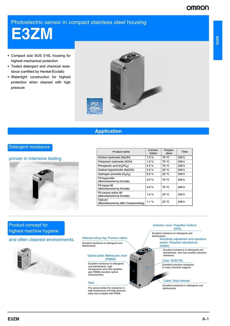
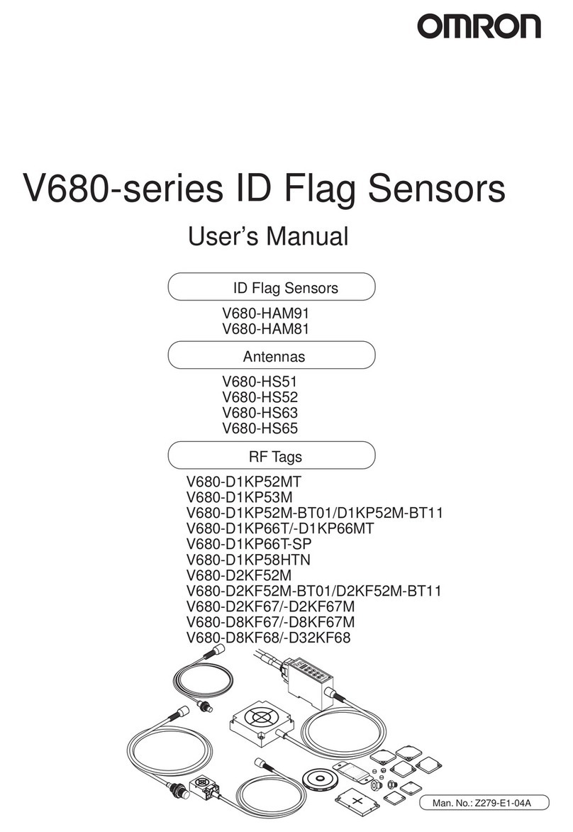
This manual suits for next models

1

Other Omron Accessories manuals

Omron ZW-XC7 User manual

Omron

Omron ZW-XC7 User manual

Omron ZFV-SC50 Series User manual

Omron

Omron ZFV-SC50 Series User manual

Omron E3ZM - User manual

Omron

Omron E3ZM - User manual

Omron ZW-S7010 Operating instructions

Omron

Omron ZW-S7010 Operating instructions

Omron SYSMAC FH Series User guide

Omron

Omron SYSMAC FH Series User guide

Omron E32-L25T User manual

Omron

Omron E32-L25T User manual

Omron E3AS-HL150 Series User manual

Omron

Omron E3AS-HL150 Series User manual

Omron E3ZM-C - User manual

Omron

Omron E3ZM-C - User manual

Omron E3X-NL - User manual

Omron

Omron E3X-NL - User manual

Omron SYSMAC C200H-IDS01-V1 User manual

Omron

Omron SYSMAC C200H-IDS01-V1 User manual

Omron E3X-MDA Series User manual

Omron

Omron E3X-MDA Series User manual

Omron E3U-GS User manual

Omron

Omron E3U-GS User manual

Omron E2AX - User manual

Omron

Omron E2AX - User manual

Omron ZX-T - User manual

Omron

Omron ZX-T - User manual

Omron E3NT-L User manual

Omron

Omron E3NT-L User manual

Omron ZG2-WDC11 User manual

Omron

Omron ZG2-WDC11 User manual

Omron E3MC - User manual

Omron

Omron E3MC - User manual

Omron F3SH-A - User manual

Omron

Omron F3SH-A - User manual

Omron ZX2 Series How to use

Omron

Omron ZX2 Series How to use

Omron MX2 COMPONET OPTION BOARD User manual

Omron

Omron MX2 COMPONET OPTION BOARD User manual

Omron SYSMAC CJ2H-CPU6@-EIP Instruction Manual

Omron

Omron SYSMAC CJ2H-CPU6@-EIP Instruction Manual

Omron F3S-TGR-CL_B User manual

Omron

Omron F3S-TGR-CL_B User manual

Omron Z4LB V2 User manual

Omron

Omron Z4LB V2 User manual

Omron E3C-LD11 User manual

Omron

Omron E3C-LD11 User manual

Popular Accessories manuals by other brands

Esco Medical MIRI TL 6 user manual

Esco Medical

Esco Medical MIRI TL 6 user manual

Wen 56380i quick start guide

Wen

Wen 56380i quick start guide

S+S Regeltechnik AERASGARD RFTM-LQ-CO2 Operating Instructions, Mounting & Installation

S+S Regeltechnik

S+S Regeltechnik AERASGARD RFTM-LQ-CO2 Operating Instructions, Mounting & Installation

Chef's Choice 220 instructions

Chef's Choice

Chef's Choice 220 instructions

RME Audio ADI-6432 user guide

RME Audio

RME Audio ADI-6432 user guide

schmersal CSS 30S operating instructions

schmersal

schmersal CSS 30S operating instructions

SIGMA TEK BWH 011 operating manual

SIGMA TEK

SIGMA TEK BWH 011 operating manual

turck FCS-GL1/2HC22-NAEX-H1141 manual

turck

turck FCS-GL1/2HC22-NAEX-H1141 manual

Gleason Reel Dual Hose Reel-Direct Drive K24 Installation and maintenance instructions

Gleason Reel

Gleason Reel Dual Hose Reel-Direct Drive K24 Installation and maintenance instructions

Multitech Reveal user guide

Multitech

Multitech Reveal user guide

MGF B/SAFE Use and maintenance manual

MGF

MGF B/SAFE Use and maintenance manual

schmersal RSS 36-I1-D-ST manual

schmersal

schmersal RSS 36-I1-D-ST manual

GESTRA NRG 16-60 Installation & operating manual

GESTRA

GESTRA NRG 16-60 Installation & operating manual

Alula RE101 quick guide

Alula

Alula RE101 quick guide

Westfalia Wetekom Master-Slave operating instructions

Westfalia

Westfalia Wetekom Master-Slave operating instructions

Summit Solo Performer manual

Summit

Summit Solo Performer manual

ATN NVG-7 user guide

ATN

ATN NVG-7 user guide

Express Controls EZMotion user manual

Express Controls

Express Controls EZMotion user manual

manuals.online logo
manuals.online logoBrands
  • About & Mission
  • Contact us
  • Privacy Policy
  • Terms and Conditions

Copyright 2025 Manuals.Online. All Rights Reserved.