1
EVO-ALLV2_HondaAcura.indd
RELEASE
Release the programming
button when the Red LED is
ON.
Insert the required remaining
connectors.
Release the programming
button when the LED is RED.
If the LED is not solid RED
disconnect the 4 Pin
connector (Data-Link) and go
back to step 1.
Insert the required remaining
connectors.
2
3
4
ON RED
ROUGE
Insérez les connecteurs requis
restants.
Relâchez le bouton de
programmation quand la DEL
est ROUGE.
Si le DEL n'est pas ROUGE
solide débranchez le
connecteur 4 pins (Data-Link)
et allez à l'étape 1.
Press and release the
programming button
twice (2x).
x2
PRESS
Appuyez et relâchez 2 fois le
bouton de programmation.
LOCK
ACC ON
PUSH
START
IGN
FLASH 10X
IGNITION ON
6
FLASH RAPIDLY IGNITION OFF
LOCK
ACC ON
PUSH
START
OFF
OFF
The RED LED will flash
rapidly 10x times.
The BLUE LED will flash
rapidly.
Key bypass programmed.
CAN-Bus programmed.
AN-Bus programmed.
La DEL ROUGE clignotera
10x fois rapidement.
La DEL BLEU clignotera
rapidement:
Contournement de clé
programmé.
Réseau CAN programmé.
The BLUE LED will turn off. La DEL BLEU s'éteint.
TURN
ON/RUN
TURN
OFF
5
FLASH 10X
FLASH
The module is now
programmed.
Le module est
programmé.
Use the remote of the remote
starter or security system to test
all of the supported features to
ensure proper programming.
Testez toutes les fonctions
supportées sur le véhicule avec la
télécommande du démarreur à
distance ou du système de sécurité.
Press and hold the
programming button:
Connect the 4-PIN Data-link
harness (Black connector).
The Blue, Red, Yellow and
Blue & Red LEDs will
alternatively illuminate.
Appuyez et maintenir
enfoncé le bouton de
programmation: Branchez le
harnais Data-Link à 4-Broches
(connecteur Noir)
Les DELs Bleue, Rouge,
Jaune et Bleue & Rouge
s'allumeront alternativement.
Tournez la clé à Ignition.
Turn the key to the
Ignition ON/RUN position.
Turn the key to the
OFF position.
Tournez la clé à la
position Arrêt (OFF).
x1
HOLD
LED may differ depending on the module casing.
L’apparence des DELS peuvent différer selon le
boîtier du module.
The RED LED will flash
once each second.
La DEL ROUGE clignote 1
fois chaque seconde.
ON
...
1
2
3
ON Red
Rouge
Insérez les connecteurs requis
restants.
Press and release the
programming button once
(1x).
5
x1
PRESS
Appuyez et relâchez 1 fois le
bouton de programmation.
The Red LED will turn OFF
and then back ON.
La DEL Rouge s'éteindra et
se rallumera.
OFF
ON
PRESS X1
OFF
ON
ON
LOCK
ACC ON
PUSH
START
IGN
FLASH 10X
IGNITION ON
7
FLASH RAPIDLY IGNITION OFF
LOCK
ACC ON
PUSH
START
OFF
OFF
The Blue LED will flash
rapidly.
CAN-Bus programmed.
La DEL Bleue clignotera
rapidement:
Réseau CAN programmé.
The Blue LED will turn off. La DEL Bleue s'éteint.
TURN
ON/RUN
TURN
OFF
6
FLASH 10X
Press and release the
programming button once
(1x).
x1
PRESS
Appuyez et relâchez 1 fois le
bouton de programmation.
The Red LED will flash 1
once each second.
La DEL Rouge clignote 1
fois chaque seconde.
FLASH
ON
PRESS X1
...
FLASH
x1
HOLD
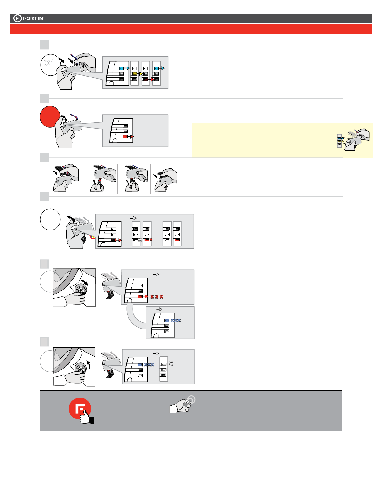
Press and hold the
programming button:
Insert the 4-Pin (Data-Link)
connector.
Appuyez et maintenir
enfoncé le bouton de
programmation:
Insérez le connecteur 4 pins
(Data-Link)
The Blue, Red, Yellow and
Blue & Red LEDs will
alternatively illuminate.
Les DELs Bleue, Rouge,
Jaune et Bleue & Rouge
s'allumeront alternativement.
Relâchez le bouton de
programmation quand la DEL
Rouge est allumée.
If the Red LED is not ON solid
disconnect the 4-PIN Data-Link
harness (Black connector) and
go back to step 1.
Si la DEL Rouge n'est pas
allumée, débranchez le harnais
Data-Link à 4-Pins et retournez
au début de l'étape 1.
Turn the key to the Ignition
ON/RUN position.
Tournez la clé à la position
Allumage ON/RUN.
Turn the key to the OFF
position.
Tournez la clé à la position
Arrêt (OFF)
The module is now
programmed.
Le module est
programmé.
Use the remote of the remote starter /
security system to test all the
supported features and ensure all the
features are properly programmed.
Testez toutes les fonctions supportées sur
le véhicule avec la télécommande du
démarreur à distance / système de sécurité
afin de vous assurer que toutes les
fonctions sont bien programmées.
The Red LED will flash 10
times rapidly.
Key bypass programmed.
La DEL Rouge clignotera
10 fois rapidement.
Contournement de clé
programmé.
1
EVO-ALLV2_HondaAcura.indd
Release the programming
button when the Red LED is
ON.
Insert the required remaining
connectors.
Release the programming
button when the LED is RED.
If the LED is not solid RED
disconnect the 4 Pin
connector (Data-Link) and go
back to step 1.
Insert the required remaining
connectors.
2
3
4
ON RED
ROUGE
Insérez les connecteurs requis
restants.
Relâchez le bouton de
programmation quand la DEL
est ROUGE.
Si le DEL n'est pas ROUGE
solide débranchez le
connecteur 4 pins (Data-Link)
et allez à l'étape 1.
Press and release the
programming button
twice (2x).
x2
PRESS
Appuyez et relâchez 2 fois le
bouton de programmation.
LOCK
ACC ON
PUSH
START
IGN
FLASH 10X
IGNITION ON
6
FLASH RAPIDLY IGNITION OFF
LOCK
ACC ON
PUSH
START
OFF
OFF
The RED LED will flash
rapidly 10x times.
The BLUE LED will flash
rapidly.
Key bypass programmed.
CAN-Bus programmed.
AN-Bus programmed.
La DEL ROUGE clignotera
10x fois rapidement.
La DEL BLEU clignotera
rapidement:
Contournement de clé
programmé.
Réseau CAN programmé.
The BLUE LED will turn off. La DEL BLEU s'éteint.
TURN
ON/RUN
TURN
OFF
5
FLASH 10X
FLASH
The module is now
programmed.
Le module est
programmé.
Use the remote of the remote
starter or security system to test
all of the supported features to
ensure proper programming.
Testez toutes les fonctions
supportées sur le véhicule avec la
télécommande du démarreur à
distance ou du système de sécurité.
Press and hold the
programming button:
Connect the 4-PIN Data-link
harness (Black connector).
The Blue, Red, Yellow and
Blue & Red LEDs will
alternatively illuminate.
Appuyez et maintenir
enfoncé le bouton de
programmation: Branchez le
harnais Data-Link à 4-Broches
(connecteur Noir)
Les DELs Bleue, Rouge,
Jaune et Bleue & Rouge
s'allumeront alternativement.
Tournez la clé à Ignition.
Turn the key to the
Ignition ON/RUN position.
Turn the key to the
OFF position.
Tournez la clé à la
position Arrêt (OFF).
x1
HOLD
LED may differ depending on the module casing.
L’apparence des DELS peuvent différer selon le
boîtier du module.
The RED LED will flash
once each second.
La DEL ROUGE clignote 1
fois chaque seconde.
ON
...
1
2
3
4
ON Red
Rouge
Insérez les connecteurs requis
restants.
Press and release the
programming button once
(1x).
5
x1
PRESS
Appuyez et relâchez 1 fois le
bouton de programmation.
The Red LED will turn OFF
and then back ON.
La DEL Rouge s'éteindra et
se rallumera.
OFF
ON
PRESS X1
OFF
ON
ON
LOCK
ACC ON
PUSH
START
IGN
FLASH 10X
IGNITION ON
7
FLASH RAPIDLY IGNITION OFF
LOCK
ACC ON
PUSH
START
OFF
OFF
The Blue LED will flash
rapidly.
CAN-Bus programmed.
La DEL Bleue clignotera
rapidement:
Réseau CAN programmé.
The Blue LED will turn off. La DEL Bleue s'éteint.
TURN
ON/RUN
TURN
OFF
6
FLASH 10X
Press and release the
programming button once
(1x).
x1
PRESS
Appuyez et relâchez 1 fois le
bouton de programmation.
The Red LED will flash 1
once each second.
La DEL Rouge clignote 1
fois chaque seconde.
FLASH
ON
PRESS X1
...
FLASH
x1
HOLD
Press and hold the
programming button:
Insert the 4-Pin (Data-Link)
connector.
Appuyez et maintenir
enfoncé le bouton de
programmation:
Insérez le connecteur 4 pins
(Data-Link)
The Blue, Red, Yellow and
Blue & Red LEDs will
alternatively illuminate.
Les DELs Bleue, Rouge,
Jaune et Bleue & Rouge
s'allumeront alternativement.
Relâchez le bouton de
programmation quand la DEL
Rouge est allumée.
If the Red LED is not ON solid
disconnect the 4-PIN Data-Link
harness (Black connector) and
go back to step 1.
Si la DEL Rouge n'est pas
allumée, débranchez le harnais
Data-Link à 4-Pins et retournez
au début de l'étape 1.
Turn the key to the Ignition
ON/RUN position.
Tournez la clé à la position
Allumage ON/RUN.
Turn the key to the OFF
position.
Tournez la clé à la position
Arrêt (OFF)
The module is now
programmed.
Le module est
programmé.
Use the remote of the remote starter /
security system to test all the
supported features and ensure all the
features are properly programmed.
Testez toutes les fonctions supportées sur
le véhicule avec la télécommande du
démarreur à distance / système de sécurité
afin de vous assurer que toutes les
fonctions sont bien programmées.
The Red LED will flash 10
times rapidly.
Key bypass programmed.
La DEL Rouge clignotera
10 fois rapidement.
Contournement de clé
programmé.
5
6
ON
Press releaseand the
programming button
Appuyez relâchezet
bouton de programmation.
The RED LED will flash La DEL ROUGE clignote
fois chaque seconde.
PRESS
FLASHPRESS
...
fois le
x2 X1X2
(2x).
2
twice
1
once each second.
This guide may change without notice. See www.fortin.ca for latest version.
Ce guide peut faire l’objet de changement sans préavis. Voir www.fortin.ca pour la récente version.
PROGRAMMING PROCEDURE | PROCÉDURE DE PROGRAMMATION
Page 5 / 6


