manuals.online logo
Brands
  1. Home
  2. •
  3. Brands
  4. •
  5. Fortin
  6. •
  7. Automobile Accessories
  8. •
  9. Fortin EVO-ALL User manual

Fortin EVO-ALL User manual

* HOOD PIN HOOD STATUS : THE HOOD PIN SWITCH MUST BE INSTALLED
IF THE VEHICLE CAN BE REMOTE STARTED WITH THE HOOD OPEN,
SET FUNCTION A11 TO OFF.
CONTACT
DE CAPOT
MANDATORY INSTALL | INSTALLATION OBLIGATOIRE Notice: the installation of safety
elements are mandatory. The hood pin
is an essential security element and
must be installed.
Notice: l'installation des éléments de
sécurité est obligatoire. Le contact de
capot est un élément de sécurité
essentiel et doit absolument être
installé.
THIS MODULE MUST BE INSTALLED BY A
QUALIFIED TECHNICIAN. A WRONG
CONNECTION CAN CAUSE PERMANENT
DAMAGE TO THE VEHICLE.
CE MODULE DOIT ÊTRE INSTALLÉ PAR
UN TECHNICIEN QUALIFIÉ, TOUTE
ERREUR DANS LES BRANCHEMENTS
PEUT OCCASIONNER DES DOMMAGES
PERMANENTS AU VÉHICULE.
STATUT DE CAPOT : LE CONTACT DE CAPOT, DOIT ÊTRE INSTALLÉ SI LE
VÉHICULE PEUT DÉMARRER À DISTANCE, LORSQUE LE CAPOT EST OUVERT,
PROGRAMMEZ LA FONCTION A11 À NON.
A11 OFF
NON
ADDENDUM - SUGGESTED WIRING CONFIGURATION
ADDENDA - SCHÉMA DE BRANCHEMENT SUGGÉRÉ
ALL REV.: 20210924
1-Page_entete
Parts required (Not
included)
Pièce(s) requise(s) (Non
incluse(s)) PAGE
WIRE TO WIRE DIAGRAM | SCHÉMA DE BRANCHEMENTS FIL À FIL
1x fuse 1x Fusible Page 5
THARNESS DIAGRAM | SCHÉMA DE BRANCHEMENTS HARNAIS EN T
THARNESS THAR-CHR7 1x THAR-CHR7 1x THAR-CHR7 Page 6
THARNESS THAR-CHR6 1x THAR-CHR6 1x THAR-CHR6 Page 7
FIRMWARE VERSION
VERSION LOGICIELLE
To add the rmware version and the options, use the
FLASH LINK UPDATER or FLASH LINK MOBILE tool,
sold separately.
Pour ajouter la version logicielle et les options,
utilisez l’outil FLASH LINK UPDATER
ou FLASH LINK MOBILE, vendu séparément.
74.[39]
MINIMUM
Guide # 97851
Vehicle functions supported in this diagram (functional if equipped) | Fonctions du véhicule
supportées dans ce diagramme (fonctionnelles si équipé)
Immobilizer bypass
Contournement d’immobilisateur
T-Harness
Harnais en T
Lock
Unlock
Arm
Disarm
Parking Lights (Datal-link only | seulement)
Tail gate
Tachometer
Door Status
Hood Status
Hand-Brake Status
Foot-Brake Status
OEM Remote monitoring
VEHICLE
VEHICULES
YEARS
ANNÉES
DODGE
1500, 2500,
3500, 4500 Diesel - Push-to-Start
Gas - Push-to-Start 2013-2017 • • • • • • • • • • • • • •
PUSH
START
Supported functions & Function programming | Fonctions supportées et programmation des fonctions
REGULAR, THAR-CHR7 & THAR-CHR6 INSTALLATION
INSTALLATION RÉGULIÈRE, THAR-CHR7 ET THAR-CHR6
Con-
Page 1 / 11
This guide may change without notice. See www.fortin.ca for latest version.
Ce guide peut faire l’objet de changement sans préavis. Voir www.fortin.ca pour la récente version.
2-PagesSuivantes
NOTES
Program bypass option
(Vehicle diesel only):
Programmez l’option du contournement
(vehicule diesel seulement):D1.3 Diesel mode (Vehicle diesel only)
Mode diesel (vehicule diesel seulement)
Program bypass option
(If equiped with OEM alarm):
Programmez l’option du contournement
(Si équipé d’une alarme d’origine):
D2
Unlock before / Lock after (Disarm OEM
alarm)
Déverrouille avant / Verrouille après
(Désarme l’alarme d’origine)
NOTES 12V BATTERY | 12V BATTERIE
ATTENTION THE T-HARNESS CURRENT
IS LIMITED AT 5 AMP MAXIMUM.
If a parking lights (+) wire is use : that require more than
5Amp. Connect the remote-starter’s power directly to the
vehicles battery with the appropriate fuse.
Some remote starters can not be powered through Data-Link.
In these cases connect the remote starter’s fused 12V power
wire directly to the T-Harness.
ATTENTION LE COURANT DU 12V PROVENANT DU HARNAIS-
EN-T EST LIMITÉ À 5 AMPÈRES MAXIMUM.
Si le l des lumières de stationnement (+) est utilisé: il requière plus de
5 Ampères, branchez le 12V du démarreur à distance directement à la
batterie du véhicule avec le fusible approprié.
Certains démarreurs à distance NE peuvent PAS être allimentés par le
Data-Link. Dans ce cas, branchez le 12V (avec fusible) du démarreur à
distance directement au harnais-en-T.
D6 Push-to-Start
Push-to-Start
Program bypass option:
Programmez l’option du contournement:
UNIT OPTION
OPTION UNITE DESCRIPTION
C1
OEM Remote status (Lock/Unlock)
monitoring
Suivi des status (Verrouillage/Déverrouil-
lage) de la télécommande d’origine
IF THE VEHICLE IS NOT EQUIPPED
WITH FUNCTIONAL HOOD PIN:
SI LE VÉHICULE N’EST PAS ÉQUIPÉ
D’UN CONTACT DE CAPOT FONCTIONNEL:A11 OFF
NON
Hood trigger (Output Status).
Contact de capot (état de sortie).
Page 2 / 11
This guide may change without notice. See www.fortin.ca for latest version.
Ce guide peut faire l’objet de changement sans préavis. Voir www.fortin.ca pour la récente version.
2-PagesSuivantes
DESCRIPTION | DESCRIPTION
WITH T-HARNESS - AVEC HARNAIS EN T
THAR-CHR7
Back of Push-to-Start Button
Dos du Bouton poussoir
At Parking-Light switch
Au commutateur des
lumières de stationnement Foot Brake connector
Connecteur du frein (pied)
(+) FOOT BRAKE
(-) PARKING LIGHTS
(+) 12V
(+) RUN SIGNAL
(~) DATA
GROUND
1
9 10
2 3 4
11 12
CAN HIGH Pin 6
CAN LOW Pin 14
OBD-II connector
Connecteur OBD-II
7 85 6
6
1314 15 16
Above driver kick panel. Two
connector with protection tape
Audessus du panneau latéral
côté conducteur. Deux
connecteur protégés par du
ruban adhésif
OR
OU


(+) IGNITION
(+) IGNITION


OR
OU
7
Parts Requiered | Photo & Location | Pièces Requises | Photos & Emplacements
Page 3 / 11
This guide may change without notice. See www.fortin.ca for latest version.
Ce guide peut faire l’objet de changement sans préavis. Voir www.fortin.ca pour la récente version.
2-PagesSuivantes
Yellow In A1
Purple In A2
Purple/White In A3
Green Out A4
White Out A5
Orange In A6
Orange/Black In A7
Dk.Blue In A8
Red/Blue In A9
Lt.Blue/Black A10
Black Out A11
Pink Out A12
Yellow/Black In A13
Brown/White Out A14
Pink/Black Out A15
Purple/Yellow A16
Green/White A17
Green/Red A18
White/Black A19
Lt.Blue A20
C5 Brown
C4 Gray/Black
C3 Gray
C2 Orange/Brown
C1 Orange/Green
D6 White/Red
D5 White/Blue
D4 White/Green
D3 Yellow/Red
D2 Yellow/Blue
D1 Yellow/Green
AC
D
WIRING CONNECTION | GUIDE DE BRANCHEMENTS
WITH | AVEC DATA-LINK:
ALWAYS REQUIRED
TOUJOURS REQUIS
NOT REQUIRED WITH
DATALINK
NON REQUIS EN
DATA-LINK
B
REMOTE
STARTER
DÉMARREUR
À DISTANCE
WITH | AVEC DATA-LINK:
Direct connection
Branchement directe
HOOD IN RS19
(-)
HAND BRAKE IN RS9
(-)
TRUNK RELEASE
(-) OUT RS10
(+/-) IN RS12
TACHOMETER
F
OOT
B
RAKE
(+)
IN RS13
GROUND OUT WHILE RUNNING
(-) OUT RS14
TRUNK
(-)
IN RS15
DOOR
(-) IN RS16
UNLOCK
(-) OUT RS17
LOCK
(-) OUT RS18
A15
A14
A13
A12
A11
A9
A8
A5
A4
A3
A2
Ground | Masse
(-)
RS1
12V BATTERY
RS2 IN
(+)
PARKING LIGHTS
RS3 OUT (-)
IGNITION
RS6 IN/OUT (+)
STARTER
RS7 OUT (+)
(-) Hood Status
(-) Hand Brake
(-) Trunk Release
(-/+) Tachometer
(+) Foot Brake
(+)Start
(-) Ground While Running
(-) Trunk Status
(-) Door Status
(-) Unlock
(-) Lock
A2
A3
A4
A5
A6
A7
A8
A9
A10
A11
A12
A13
A14
A15
A16
A17
A18
A19
A20
C5
C4
C3
C2
C1
D6
D5
D4
D3
D2
D1
A1
D1
D2
D3
D5
C1
C2
C5
A19
A17
A16
A7
A6
(+)IGNITION
(+)FOOT
BRAKE
Back View
Black 6-pin
Connector
Back of
Push to Start
button
Vue de dos
Connecteur
Noir de 6 pins
Au dos
du bouton
poussoir
Back View
Black 4-pin
Connector
At foot-brake
Connector
Vue de dos
Connecteur
Noir
de 4 pins
Au commutateur
de frein (pied)
12345
6 7 8 9 10
1 324
Green/Brown
Vert/Brun
(+)FOOT
BRAKE
Back View
Black 4-pin
Connector
At foot-brake
Connector
Vue de dos
Connecteur
Noir
de 4 pins
Au commutateur
de frein (pied)
1 324
Green/Brown
Vert/Brun
Back View
10-pin Black
Connector
At Parking
Lights switch
Vue de dos
Connecteur Noir
de 10-pins
Au commutateur
des lumières de
stationnement
(+)IGNITION
Pink/Lt.Green
Rose/Vert Pâle
Back View
10-pin Grey Connector
Near Start button.
Connector of electric
brake module.
Vuede dos
Connecteur Gris
de 10-pins
Près du bouton
Démarrage.
Connecteur du module
de frein électrique.
8
2 3 4
7
1
6 109
5
(-)PARKING
LIGHTS
White/Brown
Blanc/Brun
6 5 4 3 2 1
GROUND
DATA (+)START/
STOP SIGNAL
(+)12V
A20
CUT
A10 D4
D6
White/Green
Blanc/Vert Purple/Brown
Mauve/Brun
Black
Noir
Red
Rouge Pink/Lt.Green
Rose/Vert Pâle
(+)IGNITION
OR
OU
1
34
2
Back View
4-pin Grey Connector
Near Start button.
Connector of electric
brake module.
Vuede dos
Connecteur Gris
de 4-pins
Près du bouton
Démarrage.
Connecteur du module
de frein électrique.
OR
OU
Front view
OBD-II
Connector
Vue de face
Connecteur
OBD-II
Gray/White
Gris/Blanc Yellow
Jaune
(~)CAN
HIGH (~)CAN
LOW
C3 C4
1
910
2 3 4 5 7 8
11 12 13 15 16
6
14
6
6
A1/RS6
1AMP
Diode
DATA
(+) Start/Stop
(+) FootBrake
DATA
DATA
CAN HIGH
CAN LOW
(+) Igni�on
RS3 RS2 RS1A18
1K ohm
Resistor 5 Amp
Fuse
Fusible
WITH | AVEC DATA-LINK:
ALWAYS REQUIRED
TOUJOURS REQUIS
NOT REQUIRED WITH
DATALINK
NON REQUIS EN
DATA-LINK
B
REMOTE
STARTER
DÉMARREUR
À DISTANCE
WITH | AVEC DATA-LINK:
Direct connection
Branchement directe
HOOD IN RS19
(-)
HAND BRAKE IN RS9
(-)
TRUNK RELEASE
(-) OUT RS10
(+/-) IN RS12
TACHOMETER
F
OOT
B
RAKE
(+)
IN RS13
GROUND OUT WHILE RUNNING
(-) OUT RS14
TRUNK
(-)
IN RS15
DOOR
(-) IN RS16
UNLOCK
(-) OUT RS17
LOCK
(-) OUT RS18
A15
A14
A13
A12
A11
A9
A8
A5
A4
A3
A2
Ground | Masse
(-)
RS1
12V BATTERY
RS2 IN
(+)
PARKING LIGHTS
RS3 OUT (-)
IGNITION
RS6 IN/OUT (+)
STARTER
RS7 OUT (+)
(-) Hood Status
(-) Hand Brake
(-) Trunk Release
(-/+) Tachometer
(+) Foot Brake
(+)Start
(-) Ground While Running
(-) Trunk Status
(-) Door Status
(-) Unlock
(-) Lock
D1
D2
D3
D5
C1
C2
C5
A19
A17
A16
A7
A6
WIRING CONNECTION | SCHÉMA DE BRANCHEMENTS
Page 4 / 11
This guide may change without notice. See www.fortin.ca for latest version.
Ce guide peut faire l’objet de changement sans préavis. Voir www.fortin.ca pour la récente version.
2-PagesSuivantes
Yellow In A1
Purple In A2
Purple/White In A3
Green Out A4
White Out A5
Orange In A6
Orange/Black In A7
Dk.Blue In A8
Red/Blue In A9
Lt.Blue/Black A10
Black Out A11
Pink Out A12
Yellow/Black In A13
Brown/White Out A14
Pink/Black Out A15
Purple/Yellow A16
Green/White A17
Green/Red A18
White/Black A19
Lt.Blue A20
C5 Brown
C4 Gray/Black
C3 Gray
C2 Orange/Brown
C1 Orange/Green
D6 White/Red
D5 White/Blue
D4 White/Green
D3 Yellow/Red
D2 Yellow/Blue
D1 Yellow/Green
AC
D
THAR-CHR7 | WIRING CONNECTION | GUIDE DE BRANCHEMENTS
B
HOOD IN RS8
(-)
HAND BRAKE IN RS9
(-)
TRUNK RELEASE
(-) OUT RS11
(+/-) IN RS12
TACHOMETER
F
OOT
B
RAKE
(+)
IN RS13
GROUND OUT WHILE RUNNING
(-) OUT RS14
TRUNK
(-)
IN RS17
DOOR
(-) IN RS18
UNLOCK
(-) OUT RS19
LOCK
(-) OUT RS20
A15
A14
A13
A12
A11
A8
A5
A4
A3
A2
Ground | Masse
(-)
RS1
12V BATTERY
RS2 IN
(+)
PARKING LIGHTS
RS3 OUT (-)
IGNITION
RS6 IN/OUT (+)
STARTER
RS7 OUT (+)
(-) Hood Status
(-) Hand Brake
(-) Trunk Release
(-/+) Tachometer
(+) Foot Brake
(+)Start
(-) Ground While Running
(-) Trunk Status
(-) Door Status
(-) Unlock
(-) Lock
(+) Ignion
A2
A3
A4
A5
A6
A7
A8
A9
A10
A11
A12
A13
A14
A15
A16
A17
A18
A19
A20
C5
C4
C3
C2
C1
D6
D5
D4
D3
D2
D1
A1
C1
C2
C5
A19
A17
A7
A6
(+)IGNITION
(+)FOOT
BRAKE
Back View
Black 6-pin
Connector
Back of
Push to Start
button
Vue de dos
Connecteur
Noir de 6 pins
Au dos
du bouton
poussoir
Back View
Black 4-pin
Connector
At foot-brake
Connector
Vue de dos
Connecteur
Noir
de 4 pins
Au commutateur
de frein (pied)
12345
6 7 8 9 10
1 324
Green/Brown
Vert/Brun
(+)FOOT
BRAKE
Back View
Black 4-pin
Connector
At foot-brake
Connector
Vue de dos
Connecteur
Noir
de 4 pins
Au commutateur
de frein (pied)
1 324
Green/Brown
Vert/Brun
Back View
10-pin Black
Connector
At Parking
Lights switch
Vue de dos
Connecteur Noir
de 10-pins
Au commutateur
des lumières de
stationnement
(+)IGNITION
Pink/Lt.Green
Rose/Vert Pâle
Back View
10-pin Grey Connector
Near Start button.
Connector of electric
brake module.
Vuede dos
Connecteur Gris
de 10-pins
Près du bouton
Démarrage.
Connecteur du module
de frein électrique.
8
2 3 4
7
1
6 109
5
(-)PARKING
LIGHTS
White/Brown
Blanc/Brun Pink/Lt.Green
Rose/Vert Pâle
(+)IGNITION
OR
OU
1
34
2
Back View
4-pin Grey Connector
Near Start button.
Connector of electric
brake module.
Vuede dos
Connecteur Gris
de 4-pins
Près du bouton
Démarrage.
Connecteur du module
de frein électrique.
OR
OU
7
NOT USED
NE PAS UTILISER
T-HARNESS - HARNAIS EN T
THAR-CHR7-B
Choose any of the
connector present
Choisissez l'un des
connecteurs présents
Back View - 2-pin White
Connector, At CAN
junction,left side of
dash.
Vuede dos -
Connecteur Blanc de
2-pins. À la jonction
des CANS, à gauche
du tableau de bord.
T-HARNESS - HARNAIS EN T
OBD2-GENERIC
5 PIN CONN.
NOT USED
NE PAS UTILISER
MALE T-HARNESS
IGNITION PLUG
CONNECTEUR D’IGNITION
DU T-HARNAISMÂLE
FEMALE T-HARNESS
IGNITION PLUG
CONNECTEUR D’IGNITION
DU T-HARNAISFEMELLE
MALE VEHICLE
IGNITION PLUG
CONNECTEUR MÂLE
D’IGNITION
DU VÉHICULE
T-HARNESS - HARNAIS EN T
THAR-CHR7-B
T-HARNESS - HARNAIS EN T
THAR-CHR7-A
PUSH
START
7
A1/RS6
1AMP
Diode
A9
B
Black
Red 12V BATTERY
GROUND
Cut | Coupez
Cut | Coupez
ALWAYS REQUIRED
TOUJOURS REQUIS
NOT REQUIRED WITH
DATALINK
NON REQUIS EN
DATA-LINK
REMOTE
STARTER
DÉMARREUR
À DISTANCE
WITH | AVEC DATA-LINK:
Direct connection
Branchement directe
OR
OU
WITH D2D:
AVEC D2D: WITHOUT
SANS
DATA-LINK:
WITH DATA-LINK:
AVEC DATA-LINK:
Use the DATA-LINK cable
supplied wih the module.
U�lisez le câble
DATA-LINK inclus avec le
module.
A1
Black
RedB4
B3
12V Battery
Ground
6 PIN CONN.
5 PIN CONN.5 PIN CONN.
(+)FOOT BRAKE
RS3A18
1K ohm
Resistor
THAR-CHR7 | T-HARNESS WIRING CONNECTION | SCHÉMA DE BRANCHEMENT AVEC T HARNAIS
Page 5 / 11
This guide may change without notice. See www.fortin.ca for latest version.
Ce guide peut faire l’objet de changement sans préavis. Voir www.fortin.ca pour la récente version.
2-PagesSuivantes
Yellow In A1
Purple In A2
Purple/White In A3
Green Out A4
White Out A5
Orange In A6
Orange/Black In A7
Dk.Blue In A8
Red/Blue In A9
Lt.Blue/Black A10
Black Out A11
Pink Out A12
Yellow/Black In A13
Brown/White Out A14
Pink/Black Out A15
Purple/Yellow A16
Green/White A17
Green/Red A18
White/Black A19
Lt.Blue A20
C5 Brown
C4 Gray/Black
C3 Gray
C2 Orange/Brown
C1 Orange/Green
D6 White/Red
D5 White/Blue
D4 White/Green
D3 Yellow/Red
D2 Yellow/Blue
D1 Yellow/Green
AC
D
THAR-CHR6 | WIRING CONNECTION | GUIDE DE BRANCHEMENTS
B
REMOTE
STARTER
DÉMARREUR
À DISTANCE
WITH | AVEC DATA-LINK:
Direct connection
Branchement directe
HOOD IN RS19
(-)
HAND BRAKE IN RS9
(-)
TRUNK RELEASE
(-) OUT RS10
(+/-) IN RS12
TACHOMETER
F
OOT
B
RAKE
(+)
IN RS13
GROUND OUT WHILE RUNNING
(-) OUT RS14
TRUNK
(-)
IN RS15
DOOR
(-) IN RS16
UNLOCK
(-) OUT RS17
LOCK
(-) OUT RS18
A15
A14
A13
A12
A11
A8
A5
A4
A3
A2
Ground | Masse
(-)
RS1
12V BATTERY
RS2 IN
(+)
PARKING LIGHTS
RS3 OUT (-)
IGNITION
RS6 IN/OUT (+)
STARTER
RS7 OUT (+)
(-) Hood Status
(-) Hand Brake
(-) Trunk Release
(-/+) Tachometer
(+) Foot Brake
(+)Start
(-) Ground While Running
(-) Trunk Status
(-) Door Status
(-) Unlock
(-) Lock
D1
D2
D3
D5
C1
C2
C5
A19
A17
A16
A7
A6
B
REMOTE
STARTER
DÉMARREUR
À DISTANCE
WITH | AVEC DATA-LINK:
Direct connection
Branchement directe
HOOD IN RS19
(-)
HAND BRAKE IN RS9
(-)
TRUNK RELEASE
(-) OUT RS10
(+/-) IN RS12
TACHOMETER
F
OOT
B
RAKE
(+)
IN RS13
GROUND OUT WHILE RUNNING
(-) OUT RS14
TRUNK
(-)
IN RS15
DOOR
(-) IN RS16
UNLOCK
(-) OUT RS17
LOCK
(-) OUT RS18
A15
A14
A13
A12
A11
A8
A5
A4
A3
A2
Ground | Masse
(-)
RS1
12V BATTERY
RS2 IN
(+)
PARKING LIGHTS
RS3 OUT (-)
IGNITION
RS6 IN/OUT (+)
STARTER
RS7 OUT (+)
(-) Hood Status
(-) Hand Brake
(-) Trunk Release
(-/+) Tachometer
(+) Foot Brake
(+)Start
(-) Ground While Running
(-) Trunk Status
(-) Door Status
(-) Unlock
(-) Lock
A2
A3
A4
A5
A6
A7
A8
A9
A10
A11
A12
A13
A14
A15
A16
A17
A18
A19
A20
C5
C4
C3
C2
C1
D6
D5
D4
D3
D2
D1
A1
D1
D2
D3
D5
C1
C2
C5
A19
A17
A16
A7
A6
(+)IGNITION
(+)FOOT
BRAKE
Back View
Black 6-pin
Connector
Back of
Push to Start
button
Vue de dos
Connecteur
Noir de 6 pins
Au dos
du bouton
poussoir
Back View
Black 4-pin
Connector
At foot-brake
Connector
Vue de dos
Connecteur
Noir
de 4 pins
Au commutateur
de frein (pied)
12345
6 7 8 9 10
1 324
Green/Brown
Vert/Brun
(+)FOOT
BRAKE
Back View
Black 4-pin
Connector
At foot-brake
Connector
Vue de dos
Connecteur
Noir
de 4 pins
Au commutateur
de frein (pied)
1 324
Green/Brown
Vert/Brun
Back View
10-pin Black
Connector
At Parking
Lights switch
Vue de dos
Connecteur Noir
de 10-pins
Au commutateur
des lumières de
stationnement
(+)IGNITION
Pink/Lt.Green
Rose/Vert Pâle
Back View
10-pin Grey Connector
Near Start button.
Connector of electric
brake module.
Vuede dos
Connecteur Gris
de 10-pins
Près du bouton
Démarrage.
Connecteur du module
de frein électrique.
8
2 3 4
7
1
6 109
5
(-)PARKING
LIGHTS
White/Brown
Blanc/Brun
PUSH
START
Pink/Lt.Green
Rose/Vert Pâle
(+)IGNITION
OR
OU
1
34
2
Back View
4-pin Grey Connector
Near Start button.
Connector of electric
brake module.
Vuede dos
Connecteur Gris
de 4-pins
Près du bouton
Démarrage.
Connecteur du module
de frein électrique.
OR
OU
Front view
OBD-II
Connector
Vue de face
Connecteur
OBD-II
Gray/White
Gris/Blanc Yellow
Jaune
(~)CAN
HIGH (~)CAN
LOW
C3 C4
1
910
2 3 4 5 7 8
11 12 13 15 16
6
14
6
6
A1/RS6
1AMP
Diode
CAN HIGH
CAN LOW
(+) Igni�on
T-HARNESS
T-HARNESS
Lt.Blue
Bleu Pâle
Lt.Blue/Black
Bleu/Noir
6 PIN CONN.
NOT CONNECTED
NON BRANCHÉ
Black
Red
B4
B3
12V Battery
Ground
SEE | VOIR
NOTE PAGE 1
WITH | AVEC DATA-LINK:
WITH | AVEC D2D:
OU
OR
Fuse
5 Amp.
ALWAYS REQUIRED
TOUJOURS REQUIS
NOT REQUIRED WITH
DATALINK
NON REQUIS EN
DATA-LINK
WITHOUT DATA-LINK:
SANS DATA-LINK:
6 PIN CONN.
T-HARNESS
(+)FOOT BRAKE
T-HARNESS
A20
A10
RS3A18
T-HARNESS - HARNAIS EN T
THAR-CHR6
1K ohm
Resistor
THAR-CHR6 | T-HARNESS WIRING CONNECTION | SCHÉMA DE BRANCHEMENT AVEC T HARNAIS
Page 6 / 11
RELEASE
KIA RIO - PUSH-TO-START
®This Guide may change without notice. www.ifar.ca for latest version.
Ce Guide peut faire l'objet de changement sans préavis. www.ifar.ca pour la récente version. Page 5 / 8
PROGRAMMING PROCEDURE 1/3 | PROCÉDURE DE PROGRAMMATION 1/3
x
x
4
4
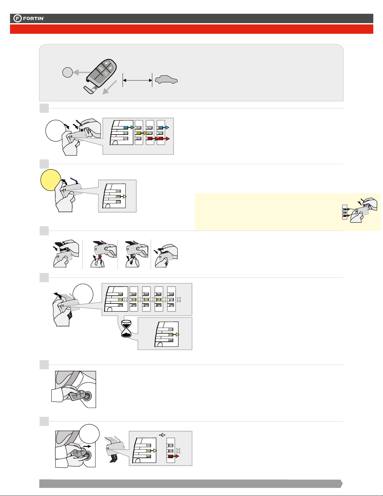
Remove the valet key from the
back of the OEM remote.
Remove the battery from the
OEM remote.
Keep the other OEM remotes
at least 3 meters (10 feet) away
from the vehicle to proceed.
10'
+
Release the programming
button when the LED is
YELLOW.
Si le DEL n'est pas JAUNE
débranchez le connecteur 4 pins
(Data-Link) et allez au début de
l'étape 1.
ON
Insert the required remaining
connectors.
FLASH
FLASH
FLASH
ON
2
3
4
Place the OEM remote (no
battery) close to the front of
START/STOP button exactly
as shown.
Do not move the OEM remote for
the following step.
CONTINUED NEXT PAGE | CONTINUEZ À LA PAGE SUIVANTE
OFF
Press and release the
programming button four
times (4x).


The YELLOW LED will
alternate between 4x flashes
and a pause.
until the YELLOW
LED turns ON.
Wait
OFF
ON
ON
5
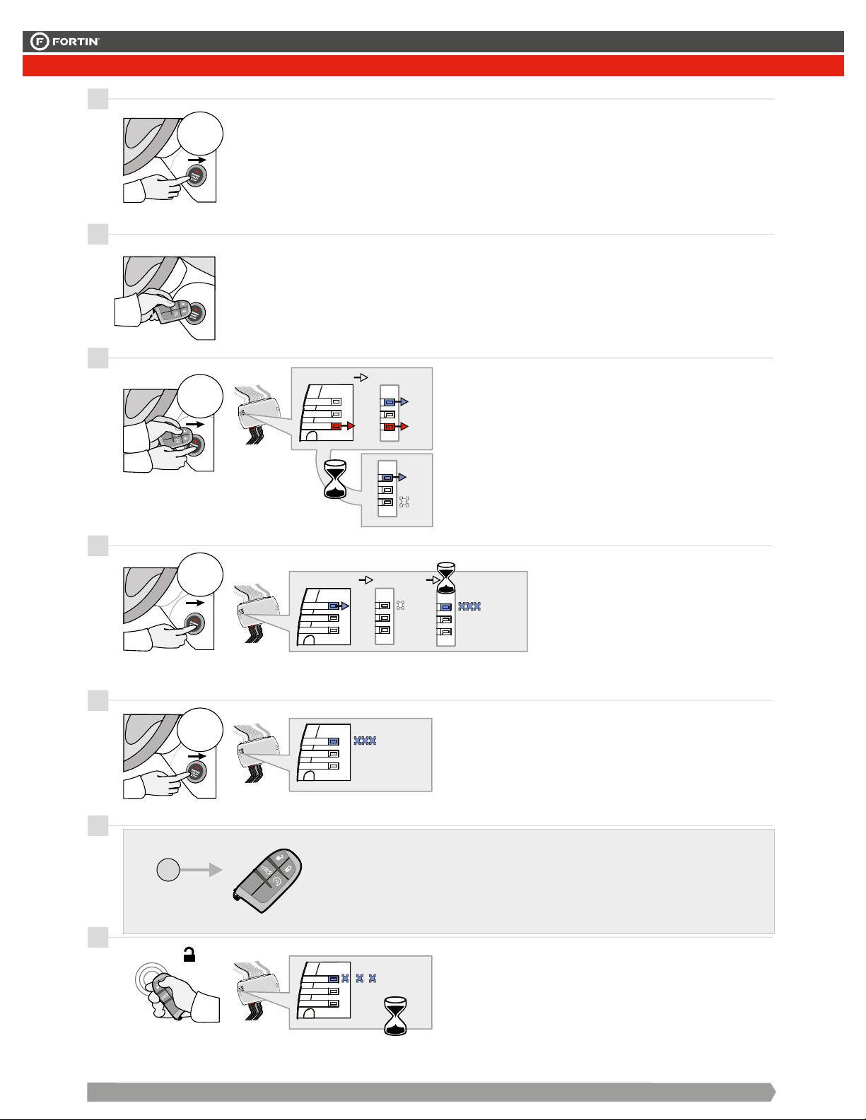
Press the Start/Stop button
twice to turn ON the ignition.
 The RED LED will turns ON.
 The YELLOW LED turns OFF.
6
PANIC
FLASH
PANIC
PANIC
x
x
2
2
ON
IGNITION OFF IGNITION ON
Retirez la clé valet du dos de
la télécommande d'origine.
Retirez la pile de la
télécommande d'origine.
Éloignez les autres
télécommandes d'origine du
véhicule (10 pieds / 3 mètres
min) pour procéder à la
programmation.
Relâchez le bouton de
programmation quand la DEL
est JAUNE.
If the LED is not solid YELLOW
disconnect the 4-Pin connector
(Data-Link) and go back to step 1.
Insérez les connecteurs requis
restants.
Approchez la télécommande
d'origine (sans batterie) devant
le bouton START/STOP
exactement comme illustrée.
Ne pas bouger la télécommande
d'origine pour l'étape suivante.
Attendre
Appuyez et relâchez 4 fois le
bouton de programmation.


La DEL JAUNE alterne entre
x 4 clignotements et x1 pause.
que la DEL
JAUNE s'allume.
Appuyez sur le bouton
START/STOP X2 fois pour
allumer l'ignition.
 La DEL ROUGE s'allume.
 La DEL JAUNE s'éteind.
1
CETTE PROGRAMMATION EST POUR LES
DODGE RAM PTS 2013
DODGE RAM PTS+THARCHR5 2013
Press and hold the
programming button:
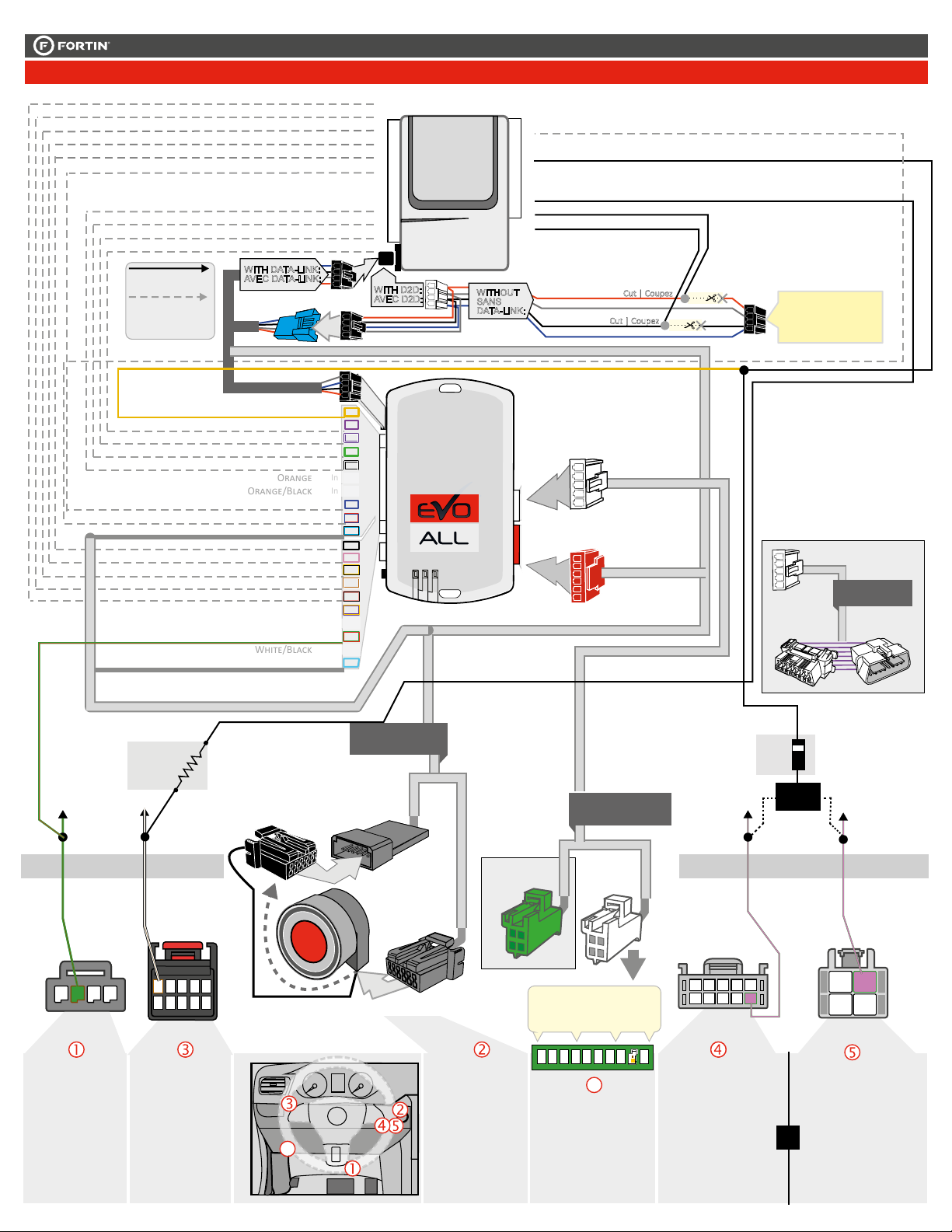
Connect the 4-PIN Data-link
harness (Black connector).
 The Blue, Red, Yellow and
Blue & Red LEDs will
alternatively illuminate.
Appuyez et maintenir
enfoncé
le bouton de
programmation:
Branchez le
harnais Data-Link à 4-Broches
(connecteur Noir)
 Les DELs Bleue, Rouge,
Jaune et Bleue & Rouge
s'allumeront alternativement.
x
x
1
1
HOLD
LED may differ depending on the module casing.
L’apparence des DELS peuvent différer selon le
boîtier du module.
This guide may change without notice. See www.fortin.ca for latest version.
Ce guide peut faire l’objet de changement sans préavis. Voir www.fortin.ca pour la récente version.
2-PagesSuivantes
KEY BYPASS PROGRAMMING PROCEDURE 1/3 | PROCÉDURE DE PROGRAMMATION CONTOURNEMENT DE CLÉ 1/3
Key Bypass Programming Procedure | Procédure de Programmation Contournement de Clé
Page 7 / 11
PROGRAMMING PROCEDURE 2/3 | PROCÉDURE DE PROGRAMMATION 2/3
8
9
11
12
Place the OEM remote (no
battery) close to the front of
START/STOP button as
shown.
Do not move the OEM remote for
the following step.
OFF
ON
ON
Press and release the
START/STOP button once to
turn ON the ACCESORY.
PANIC
PANIC
x
x
1
1
ACC
Press and release the
START/STOP button once to
shut off the ignition.
OFF
x
x
1
1
FLASH
RAPIDLY
10
x
x
1
1
ON Press and release
START/STOP button
once to turn ON the
ignition.
Reinsert the battery in the OEM remote.
Réinsérez la pile dans la télécommande d'origine.
+
PANIC
13
UNLOCK
PANIC
Unlock the doors with the
OEM remote.
FLASH
SLOWLY
cette partie de la config. est parreille a
celle dans les NISSAN CHRYSLER
SUZUKI KIZASHI
7
Press and release the
START/STOP button once to
shut off the ignition.
OFF
x
x
1
1
CONTINUED NEXT PAGE | CONTINUEZ À LA PAGE SUIVANTE
ON
ON
FLASH
RAPIDLY
IGNITION OFF ACCESORY ON
ON
ACCESORY ON IGNITION ON
OFF
IGNITION ON
Appuyez et relâchez le
bouton START/STOP pour
éteindre l'ignition.
Approchez la télécommande
d'origine (sans batterie)
devant le bouton
START/STOP comme
illustrée.
Ne pas bouger la télécommande
d'origine pour l'étape suivante.
Appuyez et relâchez le
bouton START/STOP pour
allumer l'ACCESSOIRE.
Appuyez et
relâchez le bouton
START/STOP pour
allumer l'ignition.
 The RED and BLUE LED
will turns ON.
 Wait for The RED LED
to turns OFF
 BLUE LED remains solide.
 La DEL ROUGE et BLEU
s'allument.
 Attendre que La DEL
ROUGE s'éteigne
 La DEL BLEUE reste
allumée solide.
 The BLUE LED continues
to flash rapidly.
 La DEL BLEU continue de
clignoter rapidement.
 Wait until the BLUE
LED flash rapidly.
 Attendre que la DEL
BLEU clignote rapidement.
Appuyez et relâchez 1 fois
sur le bouton START/STOP
pour éteindre l'ignition.
Déverrouillez les portes avec
la télécommande d'origine.
 Wait until the BLUE
flash slowly.
 Attendre que la DEL
BLEU clignote lentement.
This guide may change without notice. See www.fortin.ca for latest version.
Ce guide peut faire l’objet de changement sans préavis. Voir www.fortin.ca pour la récente version.
2-PagesSuivantes
KEY BYPASS PROGRAMMING PROCEDURE 2/3 | PROCÉDURE DE PROGRAMMATION CONTOURNEMENT DE CLÉ 2/3
Page 8 / 11
This guide may change without notice. See www.fortin.ca for latest version.
Ce guide peut faire l’objet de changement sans préavis. Voir www.fortin.ca pour la récente version.
2-PagesSuivantes
KEY BYPASS PROGRAMMING PROCEDURE 3/3 | PROCÉDURE DE PROGRAMMATION CONTOURNEMENT DE CLÉ 3/3
EVO-ALL
Disconnect all the connectors and after
the Data-Link (4-pins) connector.
Débranchez tous les connecteurs et ensuite
le connecteur Data-Link (4-pins).
REMOTE STARTER / ALARM VERIFICATION
PROCEDURE | PROCÉDURE DE VÉRIFICATION
DU DÉMARREUR À DISTANCE / ALARME
Test the remote starter. Remote start the vehicle.
Testez le démarreur à distance. Démarrez le véhicule
à distance.
The module is now programmed.
Le module est programmé.
*Pièces requises (non incluses)
Use the tool:
FLASH LINK UPDATER or
FLASH LINK MOBILE
to visit the DCryptor menu.
Utilisez l'outil:
FLASH LINK UPDATER ou
FLASH LINK MOBILE
pour visiter le menu DCryptor.
*Parts required (not included)
FLASH LINK UPDATER*
FLASH LINK MOBILE*
FLASH LINK MANAGER*
SOFTWARE | PROGRAMME
Microsoft Windows
Computer with
Internet connection*
Ordinateur Microsoft
Windows avec
connection Internet*
VEHICLE'S OBDII
CONNECTOR
CONNECTEUR OBDII
DU VÉHICULE
OR
OU
Smartphone*
(Internet provider
charges
may apply)
Téléphone
Intelligent*
(des frais du
fournisseur
Internet peuvent
s’appliquer)
AFTER DCRYPTOR PROGRAMMING COMPLETED
Go back to the vehicle and reconnect the 4-Pin (Data-Link)
connector and after, all the remaining connector.
APRÈS LA PROCÉDURE DE PROGRAMMATION
DCRYPTOR COMPLETÉE : retournez au véhicule et
rebranchez le connecteur 4-pins (Data-Link)
et après, tous les connecteurs du EVO-ALL.
EVO-ALL
14
15
16
Page 9 / 11
PROGRAMMING PROCEDURE 3/3 | PROCÉDURE DE PROGRAMMATION 3/3
14
EVO-ALL
EVO-ALL
FLASH LINK
UPDATER 2
ALL
EOALL
FLASH LINK
UPDATER 2
FLASH LINK MANAGER
SOFTWARE | PROGRAMME
Microsoft Windows
Computer with
Internet connection
Ordinateur Microsoft
Windows avec
connection Internet
Parts required (not included)
Pièces requises (non incluses)
16
15
REMOTE STARTER / ALARM VERIFICATION
PROCEDURE | PROCÉDURE DE VÉRIFICATION
DU DÉMARREUR À DISTANCE / ALARME
Test the remote starter. Remote start the vehicle.
Testez le démarreur à distance. Démarrez le véhicule à
distance.
The module is now programmed.
Le module est programmé.
Reconnect the 4-Pin (Data-Link) connector
and after all the remaining connector.
Rebranchez le connecteur 4-pins (Data-Link)
et après tous les connecteurs du EVO-ALL.
Connect the module to the
FLASH LINK UPDATER 2
and visit the DCryptor menu
in the Flash-Link Manager .
Branchez le module au
FLASH LINK UPDATER 2
et visitez le menu DCryptor
dans le Flash-Link Manager.
Disconnect all EVO-ALL connectors.
Débranchez tous les connecteurs du EVO-ALL.
If the vehicle is not unlocked with one of these conditions the remote-starter will shut down
as soon as any door is opened.
Si le véhicule n'est pas déverrouillé avec l'une de ces conditions, à l'ouverture de l'une des
portes, le module va éteindre le démarreur à distance et le véhicule.
Remote start
the vehicle.
Démarrez à
distance.
START
All doors must
be closed.
Toutes les
portes doivent
être fermées
UNLOCK
Enter the vehicle
with the Intelligent
Key.
Entrez dans le
véhicule avec la
clé intelligente sur
vous
The vehicle can
now be put in to
gear and
driven.
Vous êtes
maintenant prêt
à embrayer et
prendre la
route.
Unlock the doors with
either:
• The OEM remote
• The remote-starter remote
• Or the proximity remote
Déverrouillez les portes
avec soit:
• la télécommande d'origine
• la télécomande du
démarreur à distance
• ou la télécommande de
proximté.
FONCTIONNALITÉ DU DÉMARREUR À DISTANCE
REMOTE STARTER FUNCTIONNALITY
EVO-ALL
This guide may change without notice. See www.fortin.ca for latest version.
Ce guide peut faire l’objet de changement sans préavis. Voir www.fortin.ca pour la récente version.
2-PagesSuivantes
REMOTE STARTER FUNCTIONALITY | FONCTIONNALITÉS DU DÉMARREUR À DISTANCE
Remote starter functionality | Fonctionalité du démarreur à distance
Page 10 / 11
ALL
Service No : 000 102 04 2536
Date: xx-xx
INTERFACE MODULE
Made in Canada
PATENTS PENDING US: 2007-228827-A1
www.fortinbypass.com
HARDWARE VERSION
FIRMWARE VERSION
Module label | Étiquette sur le module
Notice: Updated Firmware and Installation Guides
Updated fi rmware and installation guides are posted on our web site on a regular
basis. We recommend that you update this module to the latest firmware and
download the latest installation guide(s) prior to the installation of this product.
Notice: Mise à jour microprogramme et Guides d’installations
Des mises à jour du Firmware (microprogramme) et des guides d’installation
sont mis en ligne régulièrement. Vérifiez que vous avez bien la dernière version
logiciel et le dernier guide d’installation avant l’installation de ce produit.
WARNING
The information on this sheet is provided on an (as is) basis with no representation or warranty of accuracy whatsoever.
It is the sole responsibility of the installer to check and verify any circuit before connecting to it. Only a computer safe
logic probe or digital multimeter should be used. FORTIN ELECTRONIC SYSTEMS assumes absolutely no liability or
responsibility whatsoever pertaining to the accuracy or currency of the information supplied. The installation in every case
is the sole responsibility of the installer performing the work and FORTIN ELECTRONIC SYSTEMS assumes no liability
or responsibility whatsoever resulting from any type of installation, whether performed properly, improperly or any other
way. Neither the manufacturer or distributor of this module is responsible of damages of any kind indirectly or directly
caused by this module, except for the replacement of this module in case of manufacturing defects. This module must be
installed by qualified technician. The information supplied is a guide only. This instruction guide may change without
notice. Visit www.fortinbypass.com to get the latest version.
MISE EN GARDE
L’information de ce guide est fournie sur la base de représentation (telle quelle) sans aucune garantie de précision et
d’exactitude. Il est de la seule responsabilité de l’installateur de vérifier tous les fils et circuits avant d’effectuer les connexions.
Seuls une sonde logique ou un multimètre digital doivent être utilisés. FORTIN SYSTÈMES ÉLECTRONIQUES n’assume
aucune responsabilité de l’exactitude de l’information fournie. L’installation (dans chaque cas) est la responsabilité de
l’installateur effectuant le travail. FORTIN SYSTÈMES ÉLECTRONIQUES n’assume aucune responsabilité suite à
l’installation, que celle-ci soit bonne, mauvaise ou de n’importe autre type. Ni le manufacturier, ni le distributeur ne se
considèrent responsables des dommages causés ou ayant pu être causés, indirectement ou directement, par ce module,
excepté le remplacement de ce module en cas de défectuosité de fabrication. Ce module doit être installé par un technicien
qualifié. L’information fournie dans ce guide est une suggestion. Ce guide d’instruction peut faire l’objet de changement
sans préavis. Consultez le www.fortinbypass.com pour voir la plus récente version.
Copyright © 2006-2018, FORTIN AUTO RADIO INC ALL RIGHTS RESERVED PATENT PENDING
TECH SUPPORT
Tél: 514-255-HELP (4357)
1-877-336-7797
ADDENDUM GUIDE WEB UPDATE | MISE À JOUR INTERNET
www.fortinbypass.com
EVO-ALL
Disclaimer | Avertissement
Page 11 / 11

Other manuals for EVO-ALL

21

Other Fortin Automobile Accessories manuals

Fortin PATS 1 User manual

Fortin

Fortin PATS 1 User manual

Fortin EVO ONE THAR-GM7 User manual

Fortin

Fortin EVO ONE THAR-GM7 User manual

Fortin PATS-GM2 User manual

Fortin

Fortin PATS-GM2 User manual

Fortin INT-SL User manual

Fortin

Fortin INT-SL User manual

Fortin EVO-ALL User manual

Fortin

Fortin EVO-ALL User manual

Fortin EVO ALL User manual

Fortin

Fortin EVO ALL User manual

Fortin EVO-ALL User manual

Fortin

Fortin EVO-ALL User manual

Fortin EVO ALL User manual

Fortin

Fortin EVO ALL User manual

Fortin EVO ALL User manual

Fortin

Fortin EVO ALL User manual

Fortin THAR-AUD1 User manual

Fortin

Fortin THAR-AUD1 User manual

Fortin EVO ALL User manual

Fortin

Fortin EVO ALL User manual

Fortin KEY-OVERRIDE-ALL User manual

Fortin

Fortin KEY-OVERRIDE-ALL User manual

Fortin EVO ONE User manual

Fortin

Fortin EVO ONE User manual

Fortin EVO ALL User manual

Fortin

Fortin EVO ALL User manual

Fortin EVO-ALL User manual

Fortin

Fortin EVO-ALL User manual

Fortin EVO-CHR T1 User manual

Fortin

Fortin EVO-CHR T1 User manual

Fortin EVO ALL User manual

Fortin

Fortin EVO ALL User manual

Fortin EVO ONE User manual

Fortin

Fortin EVO ONE User manual

Fortin EVO-CAN User manual

Fortin

Fortin EVO-CAN User manual

Fortin EVO ONE THAR-GM7 User manual

Fortin

Fortin EVO ONE THAR-GM7 User manual

Fortin EVO-ALL-CHRT6 User manual

Fortin

Fortin EVO-ALL-CHRT6 User manual

Fortin EVO ALL User manual

Fortin

Fortin EVO ALL User manual

Fortin EVO ONE User manual

Fortin

Fortin EVO ONE User manual

Fortin EVO KEY User manual

Fortin

Fortin EVO KEY User manual

Popular Automobile Accessories manuals by other brands

soulsens innovation BC58 manual

soulsens innovation

soulsens innovation BC58 manual

NBS-Cam MC736 user guide

NBS-Cam

NBS-Cam MC736 user guide

Car-Interface.com r.LiNK manual

Car-Interface.com

Car-Interface.com r.LiNK manual

True 4G CarWiFi How to set

True

True 4G CarWiFi How to set

Yakima RidgeBack 4 manual

Yakima

Yakima RidgeBack 4 manual

Parrot Multicomm user guide

Parrot

Parrot Multicomm user guide

Spedal CL786 user manual

Spedal

Spedal CL786 user manual

Brink 4487 Fitting instructions

Brink

Brink 4487 Fitting instructions

MUNIC C4D-4G4USAA V8+ installation guide

MUNIC

MUNIC C4D-4G4USAA V8+ installation guide

Mercedes-Benz 171.456 2005 installation instructions

Mercedes-Benz

Mercedes-Benz 171.456 2005 installation instructions

Aries S223043-2 installation manual

Aries

Aries S223043-2 installation manual

Sune Technology QHLI-LVTX-5CH-ECLIPSE installation manual

Sune Technology

Sune Technology QHLI-LVTX-5CH-ECLIPSE installation manual

Electric Life CT712 Installation instruction

Electric Life

Electric Life CT712 Installation instruction

Thule 233 manual

Thule

Thule 233 manual

Wagan 2894 user manual

Wagan

Wagan 2894 user manual

Camcar 40126 AL Mounting instructions

Camcar

Camcar 40126 AL Mounting instructions

Aldor Automotive DAI1MASU Assembly manual

Aldor Automotive

Aldor Automotive DAI1MASU Assembly manual

Directed Xpresskit DBALL2 installation guide

Directed

Directed Xpresskit DBALL2 installation guide

manuals.online logo
manuals.online logoBrands
  • About & Mission
  • Contact us
  • Privacy Policy
  • Terms and Conditions

Copyright 2025 Manuals.Online. All Rights Reserved.