Fortin EVO KEY User manual

KEY
ADDENDUM - SUGGESTED WIRING CONFIGURATION
ADDENDA - SCHÉMA DE BRANCHEMENT SUGGÉRÉ
REV.: 20210526
REGULAR INSTALLATION
INSTALLATION RÉGULIÈRE
GUIDE # 15621
Parts required (Not included) Pièce(s) requise(s) (Non incluse(s))
1X Fuse 1X Fusible
KEY
To add the rmware version and the options, use the FLASH LINK UPDATER or FLASH LINK MOBILE tool,
sold separately.
Pour ajouter la version logicielle et les options, utilisez l’outil FLASH LINK UPDATER
ou FLASH LINK MOBILE, vendu séparément.
Vehicle functions supported in this diagram (functional if equipped) | Fonctions du véhicule supportées
dans ce diagramme (fonctionnelles si équipé)
VEHICLE
VEHICULES
YEARS
ANNÉES
Immobilizer bypass
Contournement
d’immobilisateur
HYUNDAI
Veloster
Push to Start
2012-2016
•
Page 1 / 6
This guide may change without notice. See www.fortin.ca for latest version.
Ce guide peut faire l’objet de changement sans préavis. Voir www.fortin.ca pour la récente version.
DESCRIPTION |DESCRIPTION
HARDWARE VERSION FIRMWARE VERSION
VERSION DU MATÉRIEL VERSION DU LOGICIEL
Date: xx-xx
HARDWAREVERSION : 3
FIRMWAREVERSION : 4.0+
Service No : 000102 04 2536
INTERFACEMODULE
Madein Canada
PATENTSPENDING US: 2007-228827-A1
www.fortinbypass.com
EVO
4 4.09
MinimumMinimum
ADDENDUM - SUGGESTED WIRING CONFIGURATION
SCHÉMA DE BRANCHEMENT SUGGÉRÉ
VELOSTER
ALL
EOALL Page 1 / 5 Rev.20121003 GUIDE #
COMPLET REMOTE CAR STARTER INSTALLATION GUIDE
GUIDE D'INSTALLATION COMPLET DÉMARREUR À DISTANCE
Manual & Automatic transmission
Transmission Automatique et manuelle
PUSH
START
Parts required
1x Fuse Pièces requises
1x fusible
2012-2013
(-) Parking Lights Pink
(+) 12V Red
Front of Fuse panel
Devant la Boîte à fusibles
Driver Kick Panel
Panneau Latéral côté chauffeur
Behind Fuse panel
Derrière la Boîte à fusibles
Veloster Push-to-Start
(+) Start
Yellow
(+) Ignition1
Pink
(+) Ignition2
Red (~) Data Blue
This manual may change without notice.
www.ifar.ca for latest version.
Ce Guide peut faire l'objet de changement sans préavis.
www.ifar.ca pour la récente version.
Transponder bypass
Contournement de
transpondeur
Copyright © 2014,
Fortin Auto Radio Inc
Copyright © 2014,
Fortin Auto Radio Inc
Copyright © 2014,
Fortin Auto Radio Inc
Copyright © 2014,
Fortin Auto Radio Inc
Copyright © 2014,
Fortin Auto Radio Inc
Copyright © 2014,
Fortin Auto Radio Inc
Page 2 / 6

This guide may change without notice. See www.fortin.ca for latest version.
Ce guide peut faire l’objet de changement sans préavis. Voir www.fortin.ca pour la récente version.
D
A
B
C
KEY
Out A1
In A2
Out A3
In A4
A5
A6
D1
D2
D3
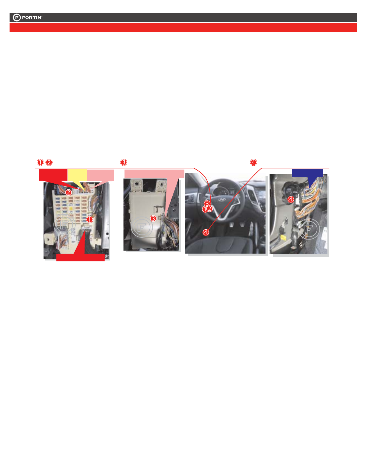
WIRING CONNECTION | GUIDE DE BRANCHEMENTS
Veloster
Data Key
Bypass
Driver Kick Panel
Back View
Panneau Latéral
côté chauffeur
Vue de dos
(-) Parking Light
(-) Lumière de
stationnement
Pink
Rose
(+) Start
Yellow
Jaune
(+) Ignition1
Pink
Rose
(+) Ignition2
Red
Rouge
(+) 12V
Red
Rouge
Blue
Bleu
Fuse panel
Back View
Boîte à fusible
Vue de dos
Fuse panel
Back View
Boîte à fusible
Vue de dos
2012-2013 2014 & +
Behind Fuse panel
Back View
Derrière la Boîte
à fusibles
Vue de dos
START
IGNITION2
PARKING LIGHT
ACCESSORY
WHILE RUNNING
12V BATTERY
Ground | Masse
REMOTE
STARTER
DÉMARREUR
À DISTANCE
(-) OUT RS18
RS8 OUT
RS6 OUT
RS5 OUT
RS4 OUT
RS2 IN
(-)
(+)
(+)
(+)
(+)
(+)
IGNITION1
RS7 OUT (+)
PARKING LIGHT
RS3 OUT (-)
WITH | AVEC DATA-LINK:
Direct connection
Branchement directe
WITH | AVEC DATA-LINK:
ALWAYS REQUIRED
TOUJOURS REQUIS
NOT REQUIRED WITH
DATALINK
NON REQUIS EN
DATA-LINK
B
Ignition
Ground While Running
(-)
(+)
RS1
A8
A2
WITHOUT | SANS DATA-LINK:
Cut | Coupez Red
Black
Blue
White
B4
B3
B2
B1
Cut | Coupez
Black
Red 12V BATTERY
Ground
B4
B3
Fuse
Must be
fused
Une fusible
doit être
installée
A5
Data Key Bypass
RS3 RS6/A2 RS8 RS7 RS2
Page 3 / 6
This guide may change without notice. See www.fortin.ca for latest version.
Ce guide peut faire l’objet de changement sans préavis. Voir www.fortin.ca pour la récente version.
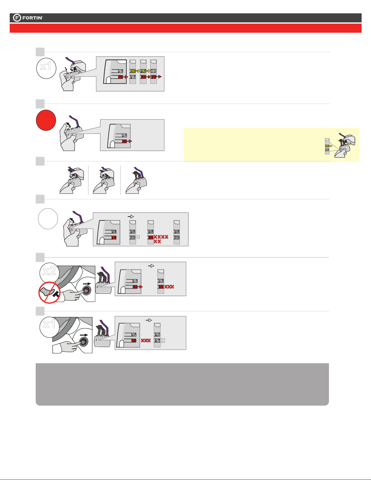
PROGRAMMING PROCEDURE |PROCÉDURE DE PROGRAMMATION
D
A
B
J
Release the programming
button when the LED is RED.
If the LED is not solid RED
disconnect the 4 Pin
connector (Data-Link
Connector) and go back to
step 1.
Insert the required remaining
connectors.
1
2
3
4
Press and hold
Insert
the
programming button:
the 4-Pin (Data-Link
Connector) connector.
Insérez les connecteurs requis
restants.
Appuyez maintenir
enfoncé
Insérez
et
le bouton de
programmation:
le connecteur 4 pins
(Connecteur Data-Link)
Relâchez le bouton de
programmation quand la DEL
est ROUGE.
Si le DEL n'est pas ROUGE
solide débranchez le
connecteur 4 pins
(Connecteur Data-Link) et
allez à l'étape 1.
The LED will alternate
between YELLOW and RED.
Les DELS alternent entre un
flash JAUNE et ROUGE.
x1
HOLD
RELEASE
The RED LED will flash
rapidly 10x times.
Key bypass programmed.
La DEL ROUGE clignotera
10x fois rapidement.
Contournement de clé
programmé.
6
IGNITIONOFF
FLASH
10X
6
D
A
B
J
FLASH RAPIDLY IGNITIONOFF
OFF
IGNITIONON
67
The module is now
programmed.
Le module est
programmé.
Use the remote of the remote
starter or security system to test
all of the supported features to
ensure proper programming.
Testez toutes les fonctions
supportées sur le véhicule avec la
télécommande du démarreur à
distance ou du système de sécurité.
D
A
B
J
...
LED may differ depending on the module casing.
L’apparence des DELS peut différer selon le boîtier du module.
D
A
B
J
ON RED
ROUGE
D
A
B
J
D
A
B
J
D
A
B
J
D
A
B
J
IGN ON
OFF
x2
PRESS
PRESS
x1
Ne pas appuyer sur la pédale de frein.
Appuyez 2 fois sur le bouton
démarrage pour allumer l'ignition.
Appuyez 1 fois sur le bouton
démarrage pour éteindre
l'ignition.
Do not press the brake pedal.
Press the START/STOP button
twice to turn ON the ignition.
Press the START/STOP button
once to turn OFF the ignition.
Press releaseand the
programming button 7 times
(7x).
Appuyez relâchezet 7 fois le
bouton de programmation.
The RED LED will flash
6 times and pause.
La DEL ROUGE clignote
6 fois et fait une pause.
x7
PRESS
D
A
B
J
FLASH X6
ON
PRESS X7
..
Page 4 / 6

This guide may change without notice. See www.fortin.ca for latest version.
Ce guide peut faire l’objet de changement sans préavis. Voir www.fortin.ca pour la récente version.
REMOTE STARTER FUNCTIONALITY |FONCTIONNALITÉS DU DÉMARREUR À DISTANCE
Remote start the
vehicle.
Démarrez à
distance.
Enter the vehicle
with the Smart-Key.
Entrez dans le
véhicule avec la clé
intelligente (Smart-
Key) sur vous
The vehicle can now
be put in to gear
and driven.
Vous êtes
maintenant prêt à
embrayer et prendre
la route.
START
Press the Push-to-
Start button twice to
turn ON the ignition.
Appuyez 2 fois sur
le bouton démarrage
(Push-to-Start) pour
allumer l'ignition.
ON
x
x
2
2
REMOTE STARTER FUNCTIONNALITY | FONCTIONNALITÉS DU DÉMARREUR À DISTANCE
Page 5 / 6
Page 6 / 8
Service No : 000 102 04 2536
Date: xx-xx
INTERFACE MODULE
Made in Canada
PATENTS PENDING US: 2007-228827-A1
www.fortinbypass.com
HARDWARE VERSION
FIRMWARE VERSION
Module label | Étiquette sur le module
Notice: Updated Firmware and Installation Guides
Updated fi rmware and installation guides are posted on our web site on a regular
basis. We recommend that you update this module to the latest firmware and
download the latest installation guide(s) prior to the installation of this product.
Notice: Mise à jour microprogramme et Guides d’installations
Des mises à jour du Firmware (microprogramme) et des guides d’installation
sont mis en ligne régulièrement. Vérifiez que vous avez bien la dernière version
logiciel et le dernier guide d’installation avant l’installation de ce produit.
WARNING
The information on this sheet is provided on an (as is) basis with no representation or warranty of accuracy whatsoever.
It is the sole responsibility of the installer to check and verify any circuit before connecting to it. Only a computer safe
logic probe or digital multimeter should be used. FORTIN ELECTRONIC SYSTEMS assumes absolutely no liability or
responsibility whatsoever pertaining to the accuracy or currency of the information supplied. The installation in every case
is the sole responsibility of the installer performing the work and FORTIN ELECTRONIC SYSTEMS assumes no liability
or responsibility whatsoever resulting from any type of installation, whether performed properly, improperly or any other
way. Neither the manufacturer or distributor of this module is responsible of damages of any kind indirectly or directly
caused by this module, except for the replacement of this module in case of manufacturing defects. This module must be
installed by qualified technician. The information supplied is a guide only. This instruction guide may change without
notice. Visit www.fortinbypass.com to get the latest version.
MISE EN GARDE
L’information de ce guide est fournie sur la base de représentation (telle quelle) sans aucune garantie de précision et
d’exactitude. Il est de la seule responsabilité de l’installateur de vérifier tous les fils et circuits avant d’effectuer les connexions.
Seuls une sonde logique ou un multimètre digital doivent être utilisés. FORTIN SYSTÈMES ÉLECTRONIQUES n’assume
aucune responsabilité de l’exactitude de l’information fournie. L’installation (dans chaque cas) est la responsabilité de
l’installateur effectuant le travail. FORTIN SYSTÈMES ÉLECTRONIQUES n’assume aucune responsabilité suite à
l’installation, que celle-ci soit bonne, mauvaise ou de n’importe autre type. Ni le manufacturier, ni le distributeur ne se
considèrent responsables des dommages causés ou ayant pu être causés, indirectement ou directement, par ce module,
excepté le remplacement de ce module en cas de défectuosité de fabrication. Ce module doit être installé par un technicien
qualifié. L’information fournie dans ce guide est une suggestion. Ce guide d’instruction peut faire l’objet de changement
sans préavis. Consultez le www.fortinbypass.com pour voir la plus récente version.
Copyright © 2006-2015, FORTIN AUTO RADIO INC ALL RIGHTS RESERVED PATENT PENDING
TECH SUPPORT
Tél: 514-255-HELP (4357)
1-877-336-7797
ADDENDUM GUIDE WEB UPDATE | MISE À JOUR INTERNET
www.fortinbypass.com
KEY
KEY
Page 6 / 6
Other Fortin Automobile Electronic manuals

Fortin
Fortin EVO ALL User manual

Fortin
Fortin Evo All THAR-VW2 User manual

Fortin
Fortin EVO-ONE User manual

Fortin
Fortin EVO ONE Installation and operating instructions

Fortin
Fortin INT-SL+ User manual

Fortin
Fortin EVO ALL Installation and operating instructions

Fortin
Fortin EVO ONE User manual

Fortin
Fortin EVO ALL User manual

Fortin
Fortin EVO ALL User manual

Fortin
Fortin EVO-ONE User manual

Fortin
Fortin EVO ALL User manual

Fortin
Fortin EVO-ONE User manual

Fortin
Fortin EvoOne 20170413 User manual

Fortin
Fortin EVO ONE User manual

Fortin
Fortin EVO ONE THAR-ONE-KHY2 User manual

Fortin
Fortin EvoOne THAR-GM1 User manual

Fortin
Fortin EVO-ALL User manual

Fortin
Fortin EVO-ALL User manual

Fortin
Fortin EVO-CAN User manual


