Fortinet FPM-7620F User manual

FPM-7620F Processing Module Guide
FortiGate-7000F Series

FORTINET DOCUMENT LIBRARY
https://docs.fortinet.com
FORTINET VIDEO GUIDE
https://video.fortinet.com
FORTINET BLOG
https://blog.fortinet.com
CUSTOMER SERVICE & SUPPORT
https://support.fortinet.com
FORTINET TRAINING & CERTIFICATION PROGRAM
https://www.fortinet.com/support-and-training/training.html
NSE INSTITUTE
https://training.fortinet.com
FORTIGUARD CENTER
https://fortiguard.com/
END USER LICENSE AGREEMENT
https://www.fortinet.com/doc/legal/EULA.pdf
FEEDBACK
Email: [email protected]
April 8, 2021
FPM-7620F Processing Module Guide
01-626-669639-20210408

TABLEOFCONTENTS
Change log 4
FPM-7620F processing module 5
FPM-7620Fmountinghardware 5
Modulelevers 5
Powersliders 6
Securescrews 6
Frontpanelinterfaces 6
PhysicalDescription 7
FrontPanelLEDs 7
Turningthemoduleonandoff 8
NMIswitch 8
NP7networkprocessors-offloadingdatatraffic 9
AcceleratedIPS,SSLVPN,andIPsecVPN(CP9contentprocessors) 9
Hardware installation 11
InstallingQSFP28andSFP28transceivers 11
Toinstalltransceivers 11
FortiGate-7121Fcablebracketkit 12
FPM-7620Fmountinghardware 12
InsertingaFPM-7620Fmoduleintoachassis 13
ShuttingdownandremovingaFPM-7620Fboardfromachassis 19
Troubleshooting 24
FPM-7620Fdoesnotstartup 24
FPM-7620FstatusLEDisflashingduringsystemoperation 25
Cautions and warnings 26
Environmentalspecifications 26
Safety 27
Regulatory notices 28
FederalCommunicationCommission(FCC)–USA 28
IndustryCanadaEquipmentStandardforDigitalEquipment(ICES)–Canada 28
EuropeanConformity(CE)-EU 28
VoluntaryControlCouncilforInterference(VCCI)–Japan 29
ProductSafetyElectricalAppliance&Material(PSE)–Japan 29
BureauofStandardsMetrologyandInspection(BSMI)–Taiwan 29
China 29
FPM-7620F Processing Module Guide 3
Fortinet Technologies Inc.

Change log Fortinet Technologies Inc.
Changelog
Date Change description
April8,2021 Removedinformationabouttheconsoleport,whichisnotsupported.Addedthe
averagepowerconsumption.
March30,2021 Minorfixes.
March16,2021 Initialrelease.
FPM-7620F Processing Module Guide 4

FPM-7620Fprocessingmodule
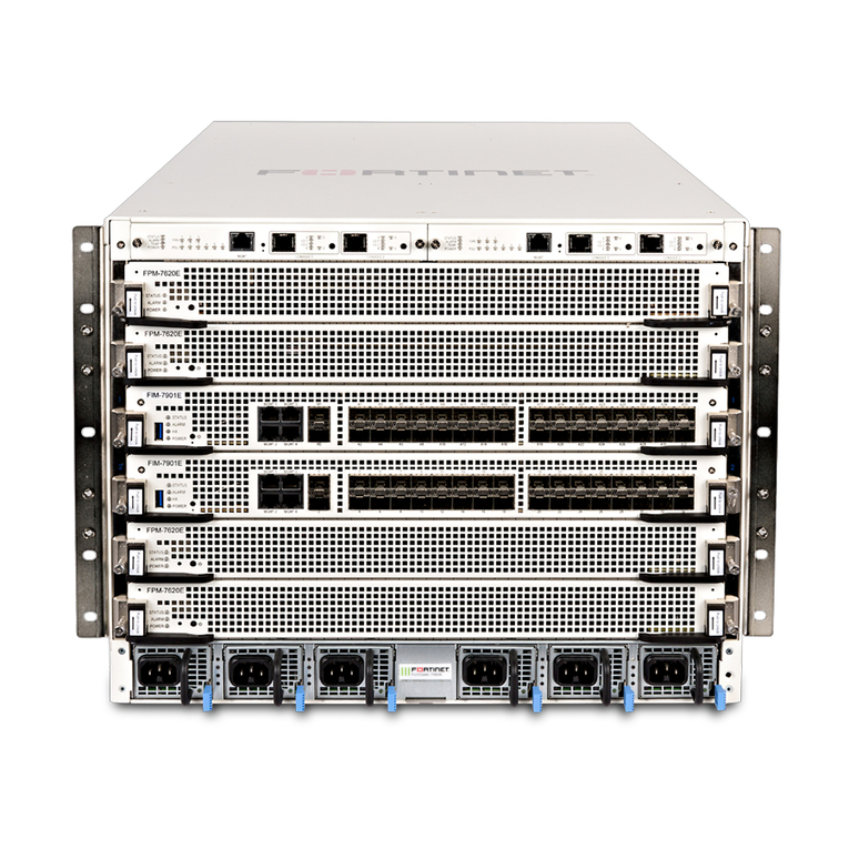
TheFPM-7620Fprocessormoduleisahigh-performanceworkermodulethatprocessessessionsloadbalancedtoitby
FIMsoverthechassisfabricbackplane.TheFPM-7620Fincludestwo400GbpsdataconnectionstotheFIMsoverthe
chassisfabricbackplaneandtwo50GbpsmanagementconnectionstotheFIMsoverbasebackplane.FPM-7620Fsare
installedinchassisslots3andup.
TheFPM-7620Falsoincludestwofrontpanel100GigEQSFP28fabricchanneldatainterfaces(1and2)andeight
10/25GigESFP28fabricchanneldatainterfaces(3to10).Interfaces1and2canbeconnectedto100Gbpsdata
networks.Interfaces3to10canbeconnectedto25Gbpsdatanetworks.FPMdatanetworkinterfacesincreasethe
numberofdatainterfacessupportedbyFortiGate-7000F.Datatrafficreceivedbytheseinterfacesissentoverthefabric
backplanetotheFIMNP7processorstobeloadbalancedbacktotheFPMs.
TheFPM-7620FprocessessessionsusingadualCPUconfiguration,acceleratesnetworktrafficprocessingwithtwo
NP7processorsandacceleratescontentprocessingwitheightCP9processors.TheNP7networkprocessorsare
connectedbytheFIMswitchfabricsoallsupportedtraffictypescanbefastpathacceleratedbytheNP7processors.
FPM-7620F front panel
Power
Slider
Module
Lever
Secure
Screw
Module
Lever
Power
Slider
Secure
Screw
Status, Alarm,
and Power LEDS
Power
Button
NMI
Button
1 and 2
100/40GigE fabric channel
QSFP28 data network
interfaces
3 to 10
25/10GigE fabric channel
SFP28 data network
interfaces
MGMT
10/100/1000BASE-T
copper management
interface
FPM-7620F mounting hardware
Usethemodulelevers,powersliders,andsecurescrewstoinsert,secureandremovethemodulefromthechassis.
Module levers
Carefullyslidethemoduleallofthewayintothechassisslotandfullyclosethemoduleleverstoseatthemoduleintothe
chassisslotandtoconnectthemoduletothechassisbackplaneconnectors.Whenbothmoduleleversarefullyclosed,
thepowersliderscanbeloweredtotheirbottomposition,lockingthemoduleleversandturningonpowertothemodule.
FPM-7620F Processing Module Guide 5
Fortinet Technologies Inc.
FPM-7620F processing module Fortinet Technologies Inc.
Raisethepowersliderstounlockthemoduleleversandturnoffmodulepower.Thenopenthemoduleleverstoejectthe
modulefromthebackplaneconnectors;allowingthemoduletoberemovedfromthechassis.
Themodulelevermechanismhelpsreducetheengagementforcerequiredtoinsertorejectthemodulefromthe
backplaneconnectors.
Themoduleleversdonotfullysecurethemoduleinthechassis.Thesecurescrewsmustbetightenedtoreliablysecure
themoduleinthechassisandtomakesurethemoduleremainssecurelyconnectedtothebackplaneforpowerand
networkconnectivity.
Power sliders
Closethemoduleleversandmovethepowersliderstotheirbottompositiontolockthemoduleleversandturnthe
modulepowerswitchon.
Movethepowersliderstothetoppositiontounlockthemoduleleversandturnthemodulepowerswitchoff.
Gentlypushthepowerslidersdowntomakesuretheyareintheirbottomposition.IfthemoduleLEDsdonotlightthe
moduleisnotreceivingpower.Ifthishappenscheckthepowersliderstomakesuretheyareintheirbottomposition.
Secure screws
Fullytightenthesecurescrewstolockthemoduleinthechassisprovidingasecureandreliableconnectionwiththe
backplane.
Loosenthesecurescrewsbeforeejectingthemodulefromthechassis.
Front panel interfaces
YouconnecttheFPM-7620Ftoyour100Gbpsnetworksusingthe1and2frontpanelQSFP28fabricchannelinterfaces.
YoucanalsoconnecttheFPM-7620Ftoyour25Gbpsnetworksusingthefrontpanel3to10SFP28fabricchannel
interfaces.Youcancreatelinkaggregationgroups(LAGs)thatcanincludedatainterfacesfrommultipleFIMsandFPMs
inthesamechassis.
Connector Type Speed Protocol Description
1and2 QSFP28 100Gbps
40Gbps
Ethernet Twofrontpanel100GigEQSFP28fabric
channeldatainterfacesthatcanbeconnected
to100Gbpsdatanetworkstodistribute
sessionstotheFPMsinchassisslots3andup.
Theseinterfacescanalsooperateas40GigE
QSFP+interfaces.
FPM-7620F Processing Module Guide 6

FPM-7620F processing module Fortinet Technologies Inc.
Connector Type Speed Protocol Description
3to10 SFP28 25Gbps
10Gbps
Ethernet Eightfrontpanel25GigESFP28fabricchannel
datainterfacesthatcanbeconnectedto
25Gbpsdatanetworkstodistributesessionsto
theFPMsinchassisslots3andup.These
interfacescanalsooperateas10GigESFP+
interfaces.
MGMT RJ-45 10Mbps
100Mbps
1000Mbps
Ethernet 10/100/1000BASE-Tcopperoutofband
managementethernetinterface.
Physical Description
Dimensions 1.69x17.11x18.56in.(43x435x471mm)(HeightxWidthxLength)
Weight 16.19lb.(7.35kg)
Operating Temperature 32to104°F(0to40°C)
Storage Temperature -13to158°F(-25to70°C)
Relative Humidity 20to90%(Non-condensing)
Power consumption Max:716W;Average:675W
Max Current 60A
Heat Dissipation 2577KJ/h(2442BTU/h)
Front Panel LEDs
LED State Description
STATUS Off TheFPM-7620Fispoweredoff.
Green TheFPM-7620Fispoweredonandoperatingnormally.
Flashing
Green
TheFPM-7620Fisstartingup.
ALARM Red Majoralarm.
Amber Minoralarm
Off Noalarms
POWER Green TheFPM-7620Fispoweredonandoperatingnormally.
FPM-7620F Processing Module Guide 7

FPM-7620F processing module Fortinet Technologies Inc.
LED State Description
Off TheFPM-7620Fispoweredoff.
1and2 Green Thecorrectcableisconnectedtotheinterfaceandtheconnectedequipment
haspowerandisconnectedat100Gbps.
Flashing
green
Networkactivityattheinterface.
Off Nolinkisestablished.
3to10
Green Thisinterfaceisconnectedat25Gbpswiththecorrectcableandthe
attachednetworkdevicehaspower.
Flashing
green
Networktrafficonthisinterface.
Off NoLink
MGMT
Link/Act
Solid
green
Indicatesthisinterfaceisconnectedwiththecorrectcableandtheattached
networkdevicehaspower.
Blinking
green
Indicatesnetworktrafficonthisinterface.
Off NoLink
MGMT
Speed
Green Connectionat1Gbps.
Amber Connectionat100Mbps.
Off Connectionat10Mbps.
Turning the module on and off
Youcanusethefrontpanelpowerbuttontoturnthemodulepoweronoroff.Ifthemoduleispoweredon,pressthe
powerswitchtoturnitoff.Ifthemoduleisturnedoffandinstalledinachassisslot,pressthepowerbuttontoturniton.
NMI switch
WhenworkingwithFortinetSupporttotroubleshootproblemswiththeFPM-7620Fyoucanusethefrontpanelnon-
maskableinterrupt(NMI)switchtoassistwithtroubleshooting.Pressingthisswitchcausesthesoftwaretodump
registers/backtracestotheconsole.Afterthedataisdumpedthemodulereboots.Whilethemoduleisrebooting,traffic
istemporarilyblocked.Themoduleshouldrestartnormallyandtrafficcanresumeoncethemoduleisupandrunning.
FPM-7620F Processing Module Guide 8

FPM-7620F processing module Fortinet Technologies Inc.
NP7 network processors - offloading data traffic
ThetwoFPM-7620FNP7networkprocessorsprovidehardwareaccelerationbyoffloadingdatatrafficfromtheFPM-
7620FCPUs.TheresultisenhancednetworkperformanceprovidedbytheNP7processorsplusthenetworkprocessing
loadisremovedfromtheCPU.TheNP7processorcanalsohandlesomeCPUintensivetasks,likeIPsecVPN
encryption/decryption.Becauseoftheintegratedswitchfabric,allsessionsarefast-pathedandaccelerated.
TrafficfromFPM-7620FfrontpaneldatainterfacesissentoverthefabricchannelbackplanetotheFIMswhereNP7
processorsuseSLBCtodistributesessionstoindividualFPMs.TheFPM-7620Fcanbeprocessingtrafficreceivedfrom
FIMdatainterfacesandfromFPMdatainterfaces.
FPM-7620F hardware architecture
Chassis Base Backplane
Chassis Fabric Backplane
Integrated Switch Fabric
2 x 50G
2 x 400G
2 x NP7
(NP#0-1)
C
2 x CPU
8 x CP9
Accelerated IPS, SSL VPN, and IPsec VPN (CP9 content processors)
TheFPM-7620FincludeseightCP9processorsthatprovidethefollowingperformanceenhancements:
lFlow-basedinspection(IPS,applicationcontroletc.)patternmatchingaccelerationwithover10Gbpsthroughput
lIPSpre-scan
lIPSsignaturecorrelation
lFullmatchprocessors
lHighperformanceVPNbulkdataengine
lIPsecandSSL/TLSprotocolprocessor
lDES/3DES/AES128/192/256inaccordancewithFIPS46-3/FIPS81/FIPS197
lMD5/SHA-1/SHA256/384/512-96/128/192/256withRFC1321andFIPS180
lHMACinaccordancewithRFC2104/2403/2404andFIPS198
lESNmode
lGCMsupportforNSA"SuiteB"(RFC6379/RFC6460)includingGCM-128/256;GMAC-128/256
FPM-7620F Processing Module Guide 9

FPM-7620F processing module Fortinet Technologies Inc.
lKeyExchangeProcessorthatsupportshighperformanceIKEandRSAcomputation
lPublickeyexponentiationenginewithhardwareCRTsupport
lPrimarycheckingforRSAkeygeneration
lHandshakeacceleratorwithautomatickeymaterialgeneration
lTrueRandomNumbergenerator
lEllipticCurvesupportforNSA"SuiteB"
lSubpublickeyengine(PKCE)tosupportupto4096bitoperationdirectly(4kforDHand8kforRSAwithCRT)
lDLPfingerprintsupport
lTTTD(Two-Thresholds-Two-Divisors)contentchunking
lTwothresholdsandtwodivisorsareconfigurable
FPM-7620F Processing Module Guide 10

Hardwareinstallation
ThischapterdescribesinstallingaFPM-7620FprocessingmoduleintoaFortiGate-7000chassis.
Installing QSFP28 and SFP28 transceivers
YoumustinstallQSFP28transceiversintotheFPM-7620Ffrontpanel1and2fabricchannelinterfacesbefore
connectingthemto100Gbpsnetworks.YoucaninstallthetransceiversbeforeorafterinsertingtheFPM-7620Fmodule
intoachassis.
YoumustinstallSFP28transceiversintotheFPM-7620Ffrontpanel3to10fabricchannelinterfacesbeforeconnecting
themto25Gbpsnetworks.YoucaninstallthetransceiversbeforeorafterinsertingtheFPM-7620Fmoduleintoa
chassis.
Accesstointerfaces6,8,and10isrestrictedbythemodulelever.Tomakeiteasiertoremove
transceivers,Fortinetrecommendsusingtransceiverswithextendedpulltabs.Anotheroption
couldbetouseacableextractiontooltoassistinremovingthesetransceivers.
To install transceivers
Tocompletethisprocedure,youneed:
lAFPM-7620F
lTransceiverstoinstall
lAnelectrostaticdischarge(ESD)preventivewriststrapwithconnectioncord
FPM-7620Fsmustbeprotectedfromstaticdischargeandphysicalshock.Onlyhandleorwork
withFPM-7620Fsatastatic-freeworkstation.Alwayswearagroundedelectrostaticdischarge
(ESD)preventivewriststrapwhenhandlingFPM-7620Fs.
Handlingthetransceiversbyholdingthereleaselatchcandamagetheconnector.Donotforce
transceiversintotheircageslots.Ifthetransceiverdoesnoteasilyslideinandclickintoplace,
itmaynotbealignedcorrectly.Ifthishappens,removethetransceiver,realignitandslideitin
again.
1. AttachtheESDwriststraptoyourwristandtoanavailableESDsocketorwriststrapterminal.
2. RemovethecapsfromthecagesocketsontheFPM-7620Ffrontpanel.
3. Holdthesidesofthetransceiverandslideitintothecagesocketuntilitclicksintoplace.
FPM-7620F Processing Module Guide 11
Fortinet Technologies Inc.

Hardware installation Fortinet Technologies Inc.
FortiGate-7121F cable bracket kit
TheFortiGate-7121Fchassisincludesanoptionalcablebracketkitthatyoucaninstalltohelpmanagethenetwork
cablesconnectedtoFIMsandFPMsinstalledinthechassis.
FPM-7620F mounting hardware
ToinstallaFPM-7620Fyouslidethemoduleintoahub/switchslotinthefrontofanFortiGate-7000serieschassis
(either3to12)andthenusethemountinghardware,describedinFPM-7620Fmountinghardwareonpage5,tolockthe
moduleintoplaceintheslot.Whenlockedintoplaceandpositionedcorrectly,themodulefrontpanelisflushwiththe
chassisfrontpanelandconnectedtothechassisbackplane.
TopositionthemodulecorrectlyyoumustusethemountinghardwareshownbelowfortherightoftheFPM-7620Ffront
panel.Themountinghardwareontheleftofthefrontpanelisthesamebutreversed.TheFPM-7620Fmounting
hardwarealignsthemoduleinthechassisslotandisusedtoinsertandejectthemodulefromtheslot.
OnsomeFPMmodulestheremaybeverylittleclearancebetweenthefrontpanelinterfaces
andthemoduleleverontherightsideoftheFPM-7620F.Infact,youmayhavetoremove
networkconnectorsfromsomefrontpanelinterfacestoopenthemodulelever.Inmostcases
youshouldremoveallnetworkconnectorsfromthefrontpanelbeforeopeningthemodule
leverstoremoveanFIMmodulefromachassisslot.
FPM-7620F Processing Module Guide 12

Hardware installation Fortinet Technologies Inc.
FPM-7620F mounting hardware
Closed
Secure Screw
Module Lever
Power Slider
Power Slider
Alignment Pin Module Lever
Secure Screw
Alignment Pin
Open
(to open move the power slider up about 2 mm)
TheFPM-7620Fmoduleleversalignthemoduleinthechassisslotandinsertandejectthemodulefromtheslot.The
powerslidersactivatemicroswitchesthatturnonorturnoffpowertothemodule.Whenbothslidersareraised,the
modulecannotreceivepower.Whentheslidersarefullyclosed,themodulecanreceivepowerifitisfullyinsertedintoa
chassisslot.
Inserting a FPM-7620F module into a chassis
ThisproceduredescribeshowtoinsertaFPM-7620Fmoduleintoslot3orupofaFortiGate-7000chassis.The
procedureincludesphotographstoillustratetheproceduresteps.ThephotosweretakeninoneofFortinet'shardware
labsusingagenericmoduleandFortiGate-7000chassis.
FPM-7620F Processing Module Guide 13

Hardware installation Fortinet Technologies Inc.
FIMandFPMbackplaneconnectorsareshippedwithabackplaneconnectorprotectionlabel
andplasticcover.BeforeinsertingtheFIMorFPMmoduleintothechassisslot,removethe
labelandplasticcoverandcheckthebackplaneconnectorstomakesuretheyarecleanand
undamaged.
ToinstallanFIMorFPMintoachassis,carefullyslidethemoduleallthewayintothechassis
slot,closethemoduleleverstoseatthemoduleintotheslot,andtightenthesecurescrewsto
makesurethemoduleisfullyengagedwiththebackplaneandsecured.Youmustalsomake
surethatthepowerslidersarefullyclosedbygentlypushingthemdown.
Installation Highlights:
1.Removebackplaneconnectorprotectionlabel.
2.Moduleleversmustbeclosed.
3.Securescrewsmustbetightened.
4.Powerslidersmustbefullyclosedforthemoduletogetpowerandstartup.
IfthemoduleisnotreceivingpowerallLEDsremainoff.
FPM-7620Fmodulesarehotswappable.Thisprocedureisthesamewhetherornotthechassisispoweredon.
DonotcarrytheFPM-7620Fmodulebyholdingthemoduleleversorsecurescrews.When
insertingorremovingtheFPM-7620Ffromachassisslot,handlethemodulebythefront
panel.Theleversarenotdesignedforcarryingthemodule.Iftheleversbecomebentor
damaged,theFPM-7620Fmaynotaligncorrectlyinthechassisslot.
Tocompletethisprocedure,youneedthefollowingequipmentandtools:
laFPM-7620F
laFortiGate-7000chassiswithanemptyslot
lanelectrostaticdischarge(ESD)preventivewriststrapwithconnectioncord
laPhillipsscrewdriver
FPM-7620Fsmustbeprotectedfromstaticdischargeandphysicalshock.Onlyhandleorwork
withFPM-7620Fsatastatic-freeworkstation.Alwayswearagroundedelectrostaticdischarge
(ESD)preventivewriststrapwhenhandlingFPM-7620Fs.AttachtheESDwriststraptoyour
wristandtoanESDsocketortoabaremetalsurfaceonthechassisorframe.(AnESDwrist
strapisnotvisibleinthephotographsbelowbecausetheyweretakeninanESDsafelab
environment.)
1. Remove the FPM-7620F module from its packaging.
Themoduleleversareclosedwhenyoufirstremoveanewmodulefromitspackaging.
Modulebackplaneconnectorsmaybecoveredbyabackplaneconnectorprotectionlabelandplasticcover.Before
insertingthemoduleintothechassisslot,removethelabelandcoverandcheckthebackplaneconnectorstomakesure
theyarecleanandundamaged.
FPM-7620F Processing Module Guide 14

Hardware installation Fortinet Technologies Inc.
2. Align the module with the chassis slot, slowly slide the module into the slot, stop at
about 1-2 inches from fully inserting it.
Module levers Module levers
Slide in slowly
Stop position
3. Unlock the left and right module levers by pushing the power sliders up until the
levers pop open.
Beforeslidingthefinalportionofthemoduleintothechassisfullyopenbothleversbypushingthepowerslidersup.Fully
openbothleverstoavoiddamagingthelevermechanism.Damagingtheleverscanpreventthemodulefromconnecting
topower.
Levers pop open
Power
slider
up
Power
slider
up
FPM-7620F Processing Module Guide 15

Hardware installation Fortinet Technologies Inc.
4. Continue pushing the module into the slot until the levers engage with the sides of
the chassis slot.
Insertthemodulebyapplyingmoderateforcetothefrontfaceplate(notthelevers)toslidethemoduleintotheslot.The
moduleshouldglidesmoothly.Ifyouencounteranyresistance,themodulecouldbealignedincorrectly.Pullthemodule
backoutandtryinsertingitagain.
Module alignment pin
inserted into chassis
Apply moderate force to
push the module slowly
into the slot. Stop Position
Levers engage with chassis
FPM-7620F Processing Module Guide 16

Hardware installation Fortinet Technologies Inc.
5. Close both levers by pushing them into contact with the module front panel.
Closingtheleversdrawsthemoduleintothechassisslotandconnectsthemodulerearconnectorstothechassis
backplane.Thedesignoftheleversleavesgapstocompensatefortolerances.Soevenwhentheleversarefullyclosed,
themodulemaynotbefullyintopositionandincontactwiththechassisbackplane.
Levers closed
Rotate to close
Small gap between the
module and the chassis
when levers are closed.
FPM-7620F Processing Module Guide 17

Hardware installation Fortinet Technologies Inc.
6. Tighten both secure screws to close the gap between the module and the chassis.
Beginbyengagingthesecurescrewsintothechassistappedholebyhandandroughlytightenthem.ThenuseaPhillips
screwdrivertofullytightenthetwosecurescrews.Donotuseapowerscrewdriver,becausethehightorqueandspeed
candamagethechassisorscrewthread.Aftertighteningbothsecurescrews,themoduleisfullyseatedinthechassis
slotandthemoduleconnectorsarefullyincontactwiththechassisbackplane.
After tightening both secure
screws, the module is fully
engaged with the chassis.
Tighten by hand
Fully tighten with a
screwdriver
FPM-7620F Processing Module Guide 18

Hardware installation Fortinet Technologies Inc.
7. Push down both power sliders to make sure the module power switch is on.
Whenthemoduleisfullyinposition,thepowerslidersshoulddropdown,lockthelevers,andturnmodulepoweron.
Gentlypushbothpowerslidersdowntotheirbottompositiontomakesuretheyarefullyclosed.
Levers locked
Power slider
down to bottom
Power slider
down to bottom
8. If the chassis is powered on, check the modle LEDs to verify that the module is
operating correctly
LED Normal operation state
Status Green
Alarm Off
HA Off
Power Green
Shutting down and removing a FPM-7620F board from a chassis
ThisproceduredescribeshowtoshutdownandremoveaFPM-7620FmodulefromFortiGate-7000chassis.The
procedureincludesphotographstoillustratetheproceduresteps.ThephotosweretakeninoneofFortinet'shardware
labsusingagenericmoduleandFortiGate-7000chassis.
FPM-7620Fsarehotswappable.Thisprocedureisthesamewhetherornotthechassisispoweredon.
FPM-7620F Processing Module Guide 19

Hardware installation Fortinet Technologies Inc.
DonotcarrytheFPM-7620Fbyholdingthemoduleleversorsecurescrews.Wheninsertingor
removingtheFPM-7620Ffromachassisslot,handlethemodulebythefrontpanel.Thelevers
arenotdesignedforcarryingthemodule.Iftheleversbecomebentordamaged,theFPM-
7620Fmaynotaligncorrectlyinthechassisslot.
Tocompletethisprocedure,youneedthefollowingequipmentandtools:
laFortiGate-7000chassiswithaFPM-7620Fmoduleinstalled
lanelectrostaticdischarge(ESD)preventivewriststrapwithconnectioncord
laPhillipsscrewdriver
FPM-7620Fsmustbeprotectedfromstaticdischargeandphysicalshock.Onlyhandleorwork
withFPM-7620Fsatastatic-freeworkstation.Alwayswearagroundedelectrostaticdischarge
(ESD)preventivewriststrapwhenhandlingFPM-7620Fs.(AnESDwriststrapisnotvisiblein
thephotographsbelowbecausetheyweretakeninanESDsafelabenvironment.)
1. Shut down the module operating system properly.
Toavoidpotentialhardwareproblems,alwaysshutdownthemoduleoperatingsystemproperlybeforeremovingthe
modulefromachassisslotorbeforepoweringdownthechassis.Toshutdownthemodule,connecttothemoduleGUI
andselectShutdownfromtheadministratormenu.Or,fromthemoduleCLI,entertheexecute shutdowncommand.
2. Disconnect all cables from the module, including all network cables and USB cables
or keys.
FPM-7620F Processing Module Guide 20
This manual suits for next models
1
Table of contents
Other Fortinet Control Unit manuals

Fortinet
Fortinet FIM-7941F User manual

Fortinet
Fortinet FortiGate-7000E Series User manual

Fortinet
Fortinet FIM-7910E User manual

Fortinet
Fortinet FIM-7904E User manual

Fortinet
Fortinet TalkSwitch 8plus Instruction Manual

Fortinet
Fortinet FIM-7920E User manual

Fortinet
Fortinet FortiFone FF-60b User manual

Fortinet
Fortinet FortiGate-7000E Series User manual