manuals.online logo
Brands
  1. Home
  2. •
  3. Brands
  4. •
  5. Fortinet
  6. •
  7. Control Unit
  8. •
  9. Fortinet TalkSwitch 8plus Instruction Manual

Fortinet TalkSwitch 8plus Instruction Manual

Installing an 8plus upgrade module
The TalkSwitch®8plus upgrade module adds eight VoIP ports to TalkSwitch systems. These
instructions outline the procedure to follow for this installation and provide words of caution
to prevent equipment damage.
Step 1: Prepare the TalkSwitch®unit for disassembly
Turn the TalkSwitch unit off, and remove all connections including incoming phone lines,
extension phone lines, LAN, and the AC adapter. It is a good idea to label the phone cords
so you know where to reconnect them. Place the unit on an anti-static mat and ground
yourself using a grounding link, or carefully follow the caution guidelines in the left margin.
Step 2: Remove top cover
Locate and remove the two screws on the bottom of the TalkSwitch unit using a Phillips
screw driver. Remove the top cover by lifting it straight up.
Step 3: Insert upgrade module into unit
The board connector pins (see TalkSwitch 48-CA or VS unit photo on reverse) on the unit
board must connect with the connector socket on the upgrade module (see 8plus upgrade
photo next page). If the steps outlined below are not done properly, you could bend the pins
and damage the board — work carefully.
1. Carefully lay the upgrade module directly on top of the unit board so that the connector
pins from the unit board match exactly with the sockets in the upgrade module
connector — do not apply pressure.
2. Look directly down the screw holes of the upgrade module and align the holes with the
hex spacers below.
3. Using your thumb, slowly apply pressure to the top of the upgrade module connector by
pressing straight down. You should feel the pins on the top board insert into the
upgrade module connector. If it is difficult to press down, stop immediately. The pins on
the unit board may not be straight and vertical. Lift the upgrade module off and realign
the connectors following the previous instructions.
4. Finish by pressing firmly on the top of the upgrade module connector. The unit
connector copper pins will be inserted into the socket on the upgrade module. (Once
inserted successfully, the pins from the unit connector appear through the top of the
upgrade module connector.)
5. Install the two screws through the upgrade module into the hex spacers below it. Do not
tighten screws too much.
Hex spacers for board
mounting screws
TalkSwitch VS unit
Locate the hex spacers and connector
positions in the photo for reference
in completing Step 3.
Board
connector pins
CAUTION: TalkSwitch unit
may be damaged if it comes in
contact with static electricity.
Make sure you are properly
grounded before proceeding. We
recommend that you use an anti-
static mat and grounding link,
otherwise follow these guidelines:
1. Don’t work on a carpet.
2. Place the upgrade module and
TalkSwitch unit on a hard
surface such as a table or
counter top.
3. Don’t pass the upgrade module
between two people. Place it on
a counter top first. The other
person can then pick it up.
Step 4: Re-attach top cover
1. Re-attach cover using information from Step 2.
Step 5: Reconnect TalkSwitch unit
1. Reconnect incoming phone lines and extension phone lines to the TalkSwitch unit.
2. Power up the TalkSwitch unit. The TalkSwitch configuration software will now identify
the four VoIP ports and are ready for configuration.
8plus module
What Next?
You should make sure you have the latest software from the TalkSwitch website at
http://www.talkswitch.com/us/en/support in the United States and Canada, or
http://global.talkswitch.com outside of North America.
To access the documentation required for VoIP line configuration, click Start on your Taskbar
and go to:
To connect to a Service Provider, refer to the appropriate VoIP Service Configuration Guide.
To configure your new VoIP lines for a multi-location network, refer to the VoIP Configuration
Guide. If you are planning to network your TalkSwitch, refer to the TalkSwitch User Guide.
Use the TalkSwitch configuration software to change settings for the new VoIP lines.
TalkSwitch 48-CA unit
Locate the hex spacers and connector
positions in the photo for reference
in completing Step 3.
8plus upgrade module
The photo on the right shows the module’s
top view, as it is inserted and mounted
into the TalkSwitch unit. Locate the holes
for the mounting screws, and the connector
socket position for reference information
required in Step 3.
Hex spacers for board
mounting screws
Board
connector pins
Holes for
mounting
screws
Connector socket
(other side of board)
We trust that this guide has been useful in your TalkSwitch system upgrade. If you have any further questions about
your TalkSwitch system upgrade, please contact your authorized TalkSwitch reseller. If you purchased directly from
TalkSwitch, visit www.talkswitch.com/us/en/support or call 1.866.393.9960 (United States and Canada).
We welcome your feedback, comments and suggestions. Please e-mail us at [email protected] or write us at
TalkSwitch, 1545 Carling Avenue, Suite 510, Ottawa, ON Canada K1Z 8P9.
www.talkswitch.com toll-free 1.888.332.9322
About TalkSwitch
TalkSwitch®, a division of Fortinet®, is a leading
developer of owner-friendly®phone systems for
small and multi-location businesses. TalkSwitch has
sold over 100,000 products that small businesses
rely on every day. With a growing global network of
resellers, distributors and partners, TalkSwitch is
changing the way small businesses communicate.
TalkSwitch is a division of Fortinet, a worldwide
provider of network security appliances and the
market leader in unified threat management (UTM).
For more information about TalkSwitch, please visit
www.talkswitch.com or call toll-free in the
United States and Canada at 1.888.332.9322. In all
other markets call +1.613.725.2980. For more infor-
mation on Fortinet and to find a reseller near you,
please visit www.fortinet.com or call
+1.866.868.3678.
Copyright © 2011 Fortinet, Inc. All rights reserved.
Fortinet®, FortiGate®, FortiGuard®, FortiCare®,
FortiManager®, FortiAnalyzer®, and TalkSwitch®are
registered trademarks of Fortinet, Inc. and other
Fortinet names herein may also be registered
trademarks and/or common law trademarks of
Fortinet. Other product or company names may be
trademarks of their respective owners.
Rev. 6/22/2011

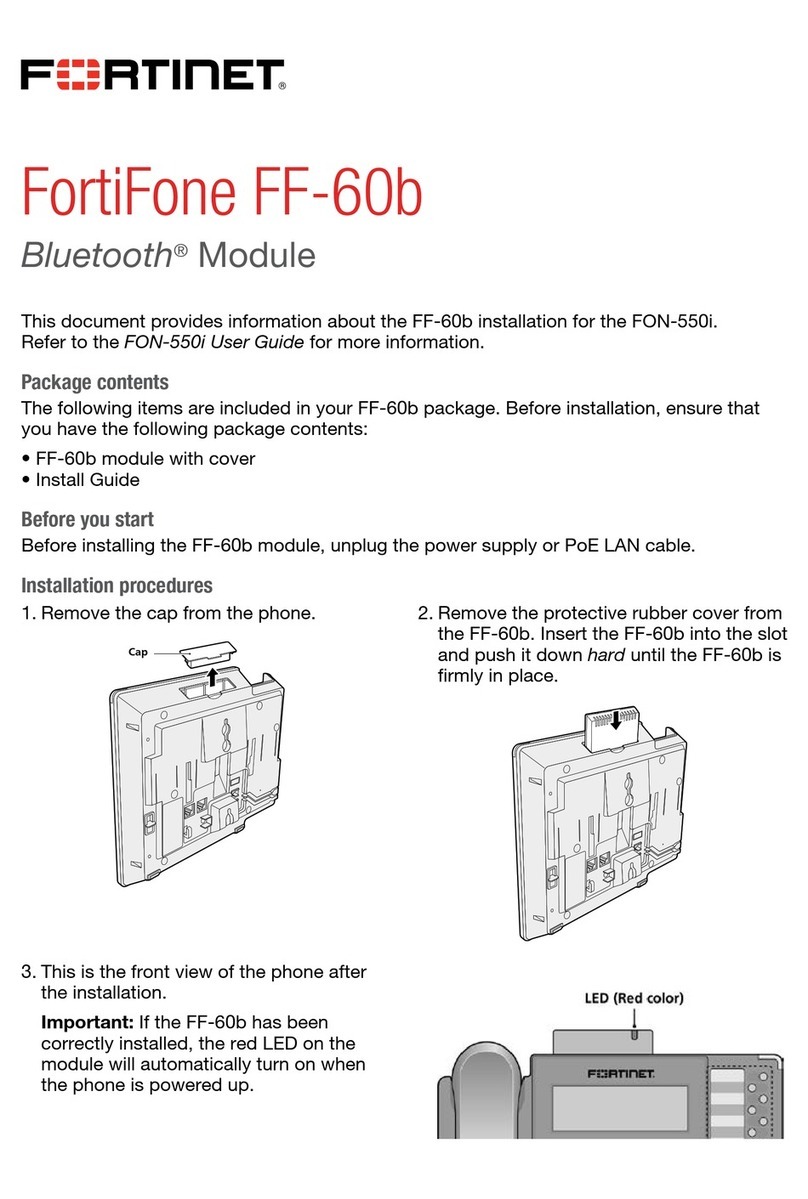
Other Fortinet Control Unit manuals

Fortinet FIM-7904E User manual

Fortinet

Fortinet FIM-7904E User manual

Fortinet FIM-7941F User manual

Fortinet

Fortinet FIM-7941F User manual

Fortinet FortiGate-7000E Series User manual

Fortinet

Fortinet FortiGate-7000E Series User manual

Fortinet FIM-7910E User manual

Fortinet

Fortinet FIM-7910E User manual

Fortinet FPM-7620F User manual

Fortinet

Fortinet FPM-7620F User manual

Fortinet FIM-7920E User manual

Fortinet

Fortinet FIM-7920E User manual

Fortinet FortiGate-7000E Series User manual

Fortinet

Fortinet FortiGate-7000E Series User manual

Fortinet FortiFone FF-60b User manual

Fortinet

Fortinet FortiFone FF-60b User manual

Popular Control Unit manuals by other brands

TriangleTube PGRKIT16 quick guide

TriangleTube

TriangleTube PGRKIT16 quick guide

ProSoft Technology ILX69-PBS user manual

ProSoft Technology

ProSoft Technology ILX69-PBS user manual

Simrig SR2 user manual

Simrig

Simrig SR2 user manual

rotork IQT3 Original instructions

rotork

rotork IQT3 Original instructions

Edwards CTM City Tie Module Installation sheet

Edwards

Edwards CTM City Tie Module Installation sheet

urmet domus Alpha 1168 Configuration manual

urmet domus

urmet domus Alpha 1168 Configuration manual

Yoshitake GD-27BP product manual

Yoshitake

Yoshitake GD-27BP product manual

Grundfos SM 113 Installation and operating instructions

Grundfos

Grundfos SM 113 Installation and operating instructions

Intel AXXRMFBU2 user guide

Intel

Intel AXXRMFBU2 user guide

King Pigeon S273 user manual

King Pigeon

King Pigeon S273 user manual

Burkert PTB 00 ATEX 2129 X operating instructions

Burkert

Burkert PTB 00 ATEX 2129 X operating instructions

Siemens SIMATIC EMS400S PSB-S operating instructions

Siemens

Siemens SIMATIC EMS400S PSB-S operating instructions

Sawo SAU-B-V2 manual

Sawo

Sawo SAU-B-V2 manual

Acromag AcroPack AP580E user manual

Acromag

Acromag AcroPack AP580E user manual

EVERSPRING AD132-1 manual

EVERSPRING

EVERSPRING AD132-1 manual

Danfoss TE 5 installation guide

Danfoss

Danfoss TE 5 installation guide

PRASTEL UNIK1E Technical Manual for the Installer

PRASTEL

PRASTEL UNIK1E Technical Manual for the Installer

Enclustra Mercury ZX1 user manual

Enclustra

Enclustra Mercury ZX1 user manual

manuals.online logo
manuals.online logoBrands
  • About & Mission
  • Contact us
  • Privacy Policy
  • Terms and Conditions

Copyright 2025 Manuals.Online. All Rights Reserved.