Fortis FXT-360A User manual

AUTOMATIC VARIABLE RESISTANCE
MAGNETIC FLYWHEEL
ELLIPTICAL CROSS TRAINER (FXT-360A)
FSAEXT360AA


Read all of the instructions in this guide before using this product. Retain this guide for
future reference. Do not skip, substitute or modify any steps or procedures in this guide, as
doing so could result in personal injury or product damage.
•Before starting any exercise program, consult your physician to determine if you have
any medical or physical conditions that could put your health and safety at risk or
prevent you from using the equipment properly. Your physician’s advice is essential if
you are taking any medication that may affect your heart rate, blood pressure or
cholesterol level.
•Incorrect or excessive exercise can damage your health. Stop exercising if you
experience any of the following symptoms: pain, tightness in your chest, irregular
heartbeat, shortness of breath, light headedness, dizziness or feelings of nausea. If you
experience any of these conditions, you should consult your physician before continuing
with your exercise program.
•This equipment is intended for adult use only. Keep children and pets away from the
machine. DO NOT leave children unattended in the same room with the equipment.
•Do not place fingers or any other objects into moving parts of the exercise equipment.
•This appliance is designed for consumer use. Follow directions and use only as
described.
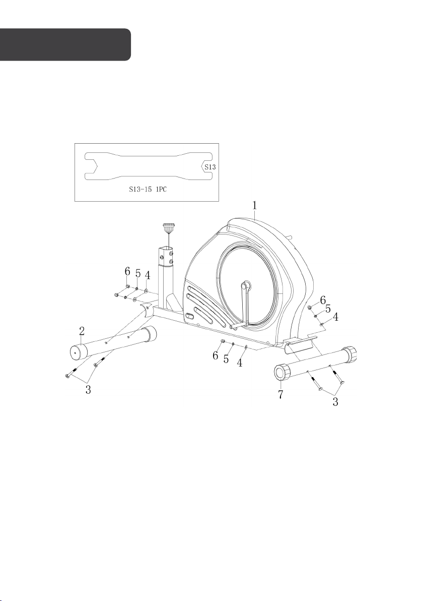
•Once fully assembled, inspect to ensure all hardware parts such as bolts, nuts and
washers are positioned correctly and tightly secured. Do not use the equipment until
this has been checked.
•Use the equipment on a solid, flat level surface with a protective cover for your floor or
carpet. To ensure safety, the equipment should have at least 50 cm of free space on
each side.
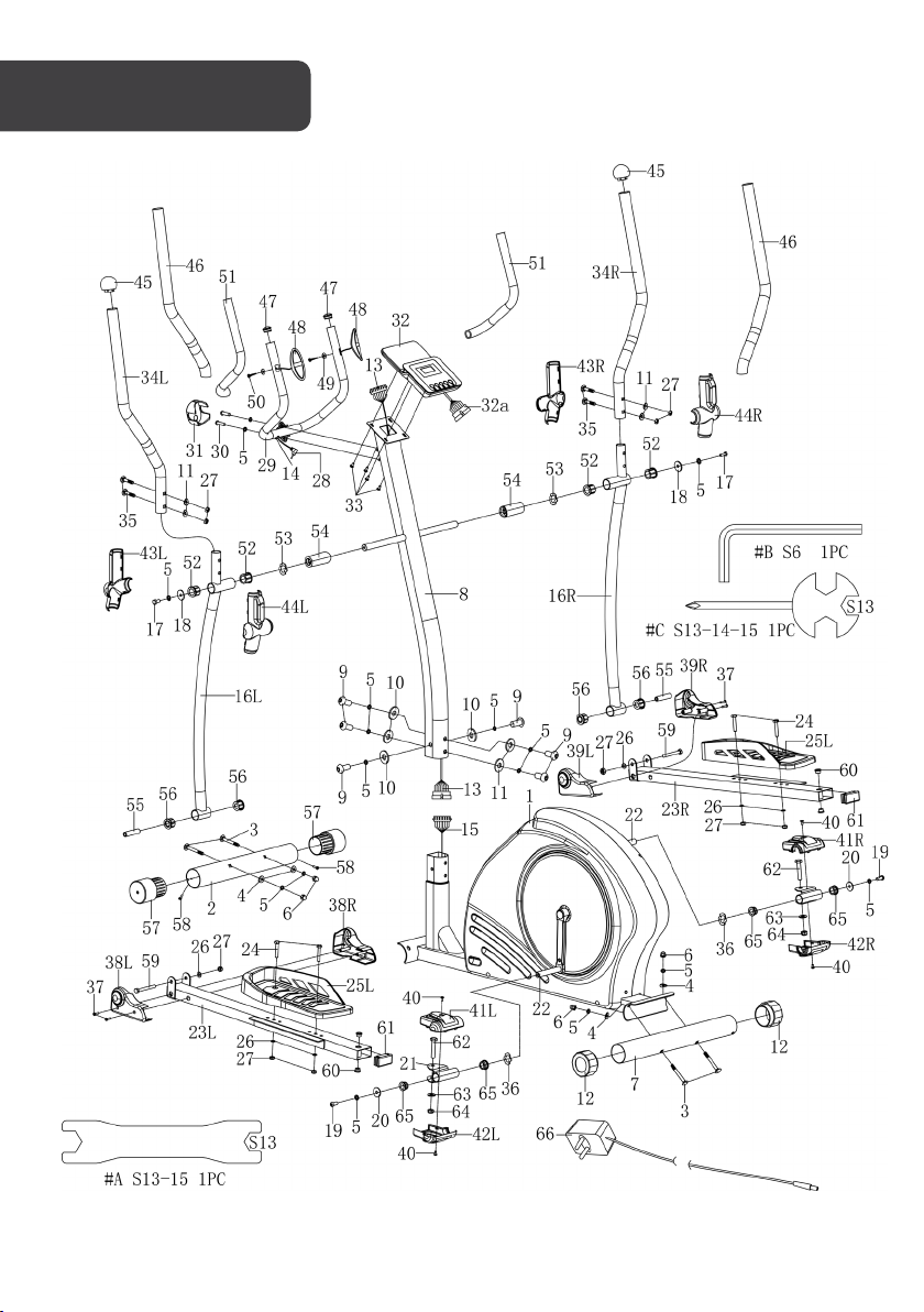
•Prior to assembly, ensure you have all the components and tools listed. Some
components are pre-assembled to help with the assembly process.
•Always use the equipment as intended. If you find any defective components while
assembling or checking the equipment, or if you hear any unusual noises coming from
the equipment during exercise, cease use immediately and contact help.kogan.com for
assistance. Do not use until resolved.
•There are many functions of the computer, which value will show when using the
equipment according to the amount of exercise, here warmly remind you that the value
of heart pulse just gives you some reference.
•Wear suitable clothing while using the equipment. Avoid wearing loose clothing that
may get caught in the equipment or that may restrict or prevent movement.
•Do not exceed the maximum user weight of 120 KG.
•This equipment is designed for indoor and family use only.
•The equipment is not suitable for therapeutic use.
SAFETY & WARNIGS

OVERVIEW

No.
Description
Qty.
No.
Description
Qty.
1
Main frame
1
19
Bolt M8 x 20 x S6
2
2
Front stabiliser
1
20
Washer d8 x Φ28 x 2
2
3
Bolt M8 x 73 x 20 x H5
4
21
Universal joint
2
4 Arc washer d8 x
Φ
20 x 2 x R30 4
22
L/R
Crank 2
5 Washer d8 16
23
L/R
Pedal supporting rod 2
6
Nut M8 x H16 x S13
4
24
Bolt M8 x 45 x 20 x S14
4
7 Rear stabiliser 1
25
L/R
Pedal 2
8
Handlebar post
1
26
Washer d8 x Φ16 x 1.5
6
9
Bolt M8 x 16 x S6
6
27
Nut M8 x H7.5 x S13
6
10
Washer d8 x Φ20 x 2
4
28
Handle pulse wire
1
11
Arc washer d8 x Φ20 x 2 x R16
6
29
Middle handlebar
1
12
End cap Φ60 x 45.5 x 74.5 x 74.5
2
30
Bolt M8 x 30 x S6
2
13
Trunk wire 1
1
31
Cover 71 x 58 x 40
1
14
Plug Φ12 x 11 x Φ3
1
32
Console
1
15
Trunk wire 2
1
33
Screw M5 x 10 x Φ10
4
16
L/R
Swing rod (L/R) 2
34
L/R
Handlebar (L/R) 2
17
Bolt M8 x 16 x S13
2
35
Bolt M8 x 43 x 20 x H5
4
18
Washer d8 x Φ32 x 2
2
36
Wave washer d17 x Φ22 x 0.3
2

No.
Description
Qty.
No.
Description
Qty.
37
Screw ST4.2 x 19 x Φ8
4
54
Bushing Φ31.8 x Φ19.2 x 77.9
2
38
L/R
Cover L/R 2
55 Bushing
Φ
14 x
Φ
8.3 x 59.5 2
39
L/R Cover L/R 2
56
Bushing 1 Φ32 x 3 x Φ28 x 16
x Φ14.3
4
40
Screw M5 x 10 x Φ9
4
57
End cap Φ60 x Φ70 x 95
2
41
L/R
Cover L/R 2
58 Screw ST3 x 10 x Φ5.6 2
42
L/R
Cover L/R 2
59 Bolt M8 x 75 x 13 x S13 2
43
L/R
Cover L/R 2
60 Plug
Φ
18 x 3 x
Φ
14 x 7 x
Φ
10.1 4
44
L/R
Cover L/R 2
61 End cap J60 x 30 x 15 2
45
End cap Φ32 x 46 x Φ50
2
62
Bolt M10 x 55 x 20 x 17
2
46
Foam grip Φ30 x 5 x 630
2
63
Washer d10 x Φ20 x 2.0
2
47
End cap Φ25 x 16
2
64
Nut M10 x H9.5 x S17
2
48 Handle pulse 2
65
Bushing Φ28 x 4 x Φ24 x 12 x
Φ16.2
4
49
washer d5 x Φ10 x 1.0
2
66
Adaptor
1
50 Screw ST4 x 19x Φ7 2
A
Spanner t4.0x 140 x 30 x S13
x S15
1
51
Foam grip Φ23 x 3 x 420
2
B
Spanner S6
1
52
Bushing 4 Φ32 x 3.5 x Φ28 x
20.5 x
Φ
19.1 4
C Spanner S13-14-15 1
53
Wave washer d19 x Φ25 x 0.3
2

Step 1:
Secure front stabiliser (2) and rear stabiliser (7) to main frame (1) with bolt (3), arc washer (4),
washer (5) and nut (6) separately.
ASSEMBLY

Step 2:
Remove the pre-installed bolt (9), washer (5), arc washer (11) and washer (10) from the
mainframe (1), please reserve for pending step.
Connect trunk wire (13) with sensor wire (15).
Secure the handlebar post (8) to the mainframe (1) with bolt (9), washer (5), arc washer (11)
and washer (10).

Step 3:
Remove the pre-installed bolt (17), washer (5) and washer (18) from the handlebar post (8),
please reserve for pending step.
Insert the swing rod (16L/R) and universal joint (21) to the fixed axle of handlebar post (8) and
crank (22) separately.
Secure the swing rod (16L/R) into the handlebar post (8) with the bolt (17), washer (5) and
washer (18) separately.
Secure the universal joint (21) to the crank (22) with bolt (19), washer (5), washer (20) and
wave washer (36).

Step 4:
Secure pedal (25L/R) to pedal supporting rod (23L/R) with bolt (24), washer (26) and nut
(27) separately.

Step 5:
Connect the console wire (32a) with trunk wire (13). Then secure the console (32) to the
handlebar post (8) with the bolt (33).
Remove the pre-installed bolt (30) and washer (5) from the handlebar post (8).
Secure the middle handlebar (29) to the handlebar post (8) with the bolt (30) and washer
(5).
Insert handle pulse wire (28) into the hole on the back of the console (32). Then attach the
cover (31).

Step 6:
Insert handlebar (34L/R) into the swing rod (16L/R) separately.
Secure the handlebar (34L/R) with bolt (35), arc washer (11) and nut (27) separately.

Step 7:
Buckle up the cover (38L) and cover (38R) to the pedal supporting rod (23L). Then fix it with
screw (37), as the diagram A.
Buckle up the cover (39L) and cover (39R) to the pedal supporting rod (23R). Then fix it with
screw (37), as the diagram B.

Step 8:
Buckle up the cover (41L) and cover (42L) to the universal joint (21). Then fix it with screw
(40), as the diagram A.
Buckle up the cover (41R) and cover (42R) to the universal joint (21). Then fix it with screw
(40), as the diagram B.

Step 9:
Buckle up the cover (44L) and cover (43L) to the swing rod (16L).
Buckle up the cover (44R) and cover (43R) to the swing rod (16R).
Before using the unit, first, insert the round plug of the adaptor (66) into the hole in the
mainframe (1). Then insert the plug into the power socket.

Motorised Computer Operation
There are 21 programs in the computer.
A: 1 manual setting
B: 10 preset program profiles (PROGRAM: P1-P10)
P1: Rolling P2: Valley
P3: Fat burn P4: Ramp
PROGRAMS

P5: Mountain P6: Interval
P7: Cardio P8: Endurance
P9: Slope P10: Rally

C: 5 custom user setting programs (CUSTOM: P11 ~ P15)
•Record the user's data of 5 User Setting Programs.
•Display Speed (RPM), TIME and WATT, CAL and DIST, at the same time

D: 1 watt control program (WATT PRO: P16)
E: 4 Heartrate control program: (PULSE PRO: P17-P20)
•55% HR, 75% HR, 95% HR and TARGET HR
•HR = Heartrate
Note:
The computer will turn off automatically if there is no operation, speed signal and
pulse signal over 4 minutes. It will store your current exercise data and run the loading
resistance to the minimum. Once you press any button or in motion, the computer will
turn on automatically.

1. ENTER
In “stop” mode, press ENTER button to enter into program selection and setting value
which flash in the related window.
•When selecting a program, press Enter to confirm selection.
•When in setting, press ENTER to confirm the value that you would like to preset.
In “start” mode, press ENTER to choose to display the speed or RPM, or to switch
automatically.
There are 10 columns of loading bars and 8 bars in each
column.
Each column represents a 1-minute workout (without the
change of TIME value) and each bar represents 2 levels of
loading.
2. START/STOP
Press the Start/Stop button to start or stop the programs.
During any mode, hold down this button for 2 seconds to reset the computer.
3. UP
In “stop” mode and the dot matrix character flash, press this button to select the program
up. If the related window value flashes, press this button to increase the value.
In “start” mode, press this button to increase the training resistance.
4. DOWN:
In “stop” mode and the dot matrix character flash, press this button to select the program
down. If the related window value flashes, press this button to decrease the value.
In “start” mode, press this button to decrease the training resistance.
5. RECOVERY
First, test your current heart rate and show your heart rate value, press this button to enter
into pulse recovery testing.
When you are in pulse recovery mode, press this button to exit.
BUTTONS
Note:
•To press or rotate of UP, DOWN button should be followed by a different model.
•It is suggested to cover your finger within the marked region to select functions in
case of any wrong action.
Table of contents
Other Fortis Fitness Equipment manuals

Fortis
Fortis FSDUM24BELLA User manual

Fortis
Fortis FSADJKTLBLA User manual

Fortis
Fortis FSADDBBS30A User manual

Fortis
Fortis FSHMGYMSTNA User manual

Fortis
Fortis FSFITNSBNHA User manual

Fortis
Fortis Suit User manual

Fortis
Fortis SK-600 User manual

Fortis
Fortis FSTNRELTPLA User manual

Fortis
Fortis FRINVSNTBLA User manual

Fortis
Fortis FSDUM40BELA User manual