Fortis FSHMGYMSTNA User manual

Gym Station
FSHMGYMSTNA
Quick Start Guide
Table of Contents
Safety & Warnings..................................................................................................................................................... 1
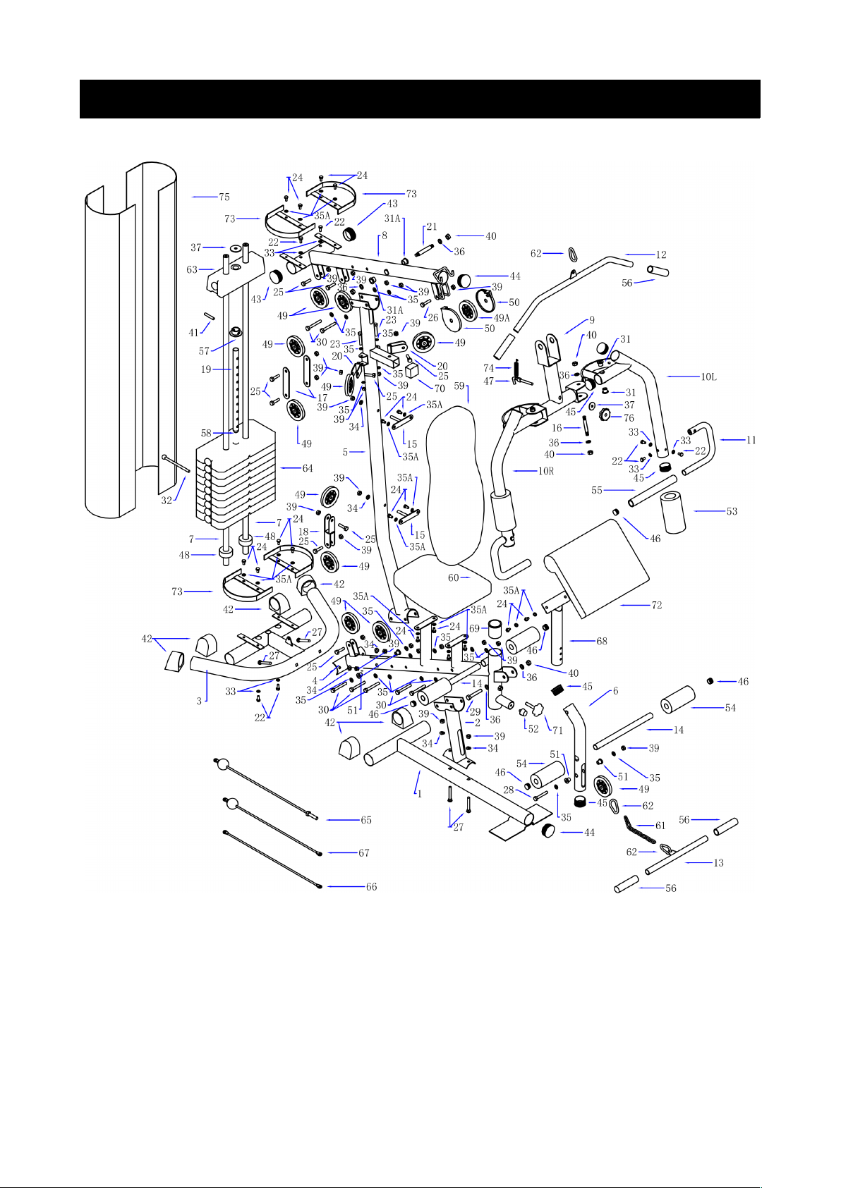
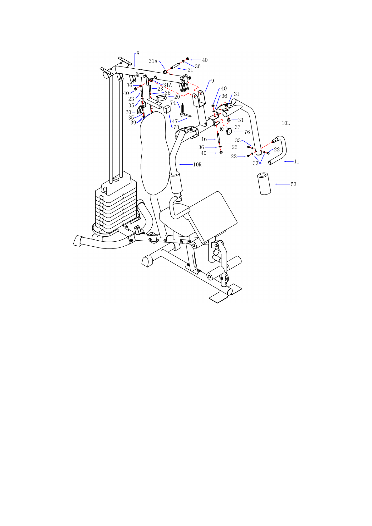
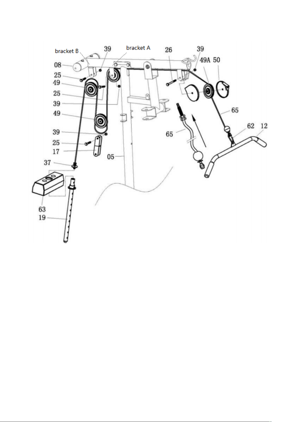
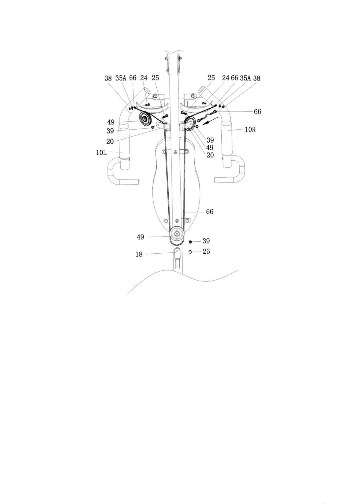
Part List........................................................................................................................................................................ 2
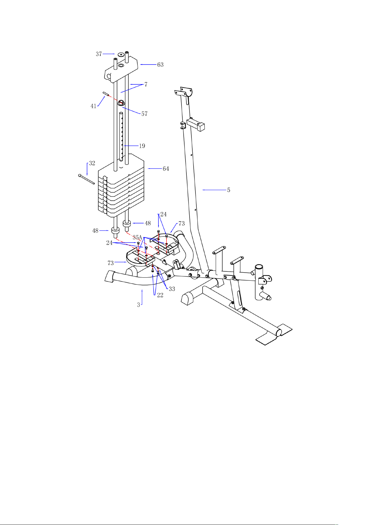
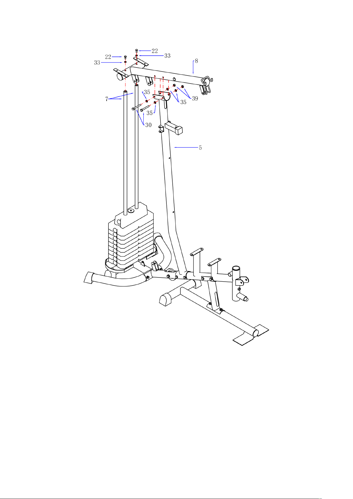
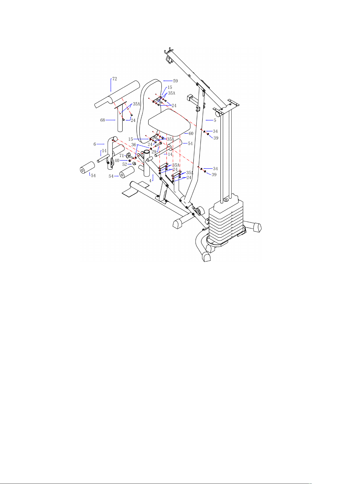
Assembly..................................................................................................................................................................... 4
Exercises.................................................................................................................................................................... 13
Safety & Warnin s
•Read all instructi ns bef re using the equipment and retain f r reference.
•Bef re starting any exercise pr gramme, y u sh uld c nsult y ur physician t determine
if y u have any medical r physical c nditi ns that c uld put y ur health and safety at
risk r prevent y u fr m using the equipment pr perly. Y ur physician’s advice is essential
if y u are taking any medicati n that may aect y ur heart rate, bl d pressure, r
ch lester l level.
•F ll w y ur b dy’s signals. Inc rrect r excessive exercise can damage y ur health. St p
exercising and c nsult y ur physician bef re c ntinuing with y ur exercise pr gram if y u
experience any f the f ll wing sympt ms: pain, tightness in y ur chest, irregular
heartbeat, sh rtness f breath, lightheadedness, dizziness, r feelings f nausea.
•Keep away fr m children and als pets. This appliance is n t intended f r use by pers ns
(including children) with reduced physical, sens ry r mental capabilities, r lack f
experience and kn wledge, unless they have been given supervisi n r instructi n
c ncerning use f the appliance by a pers n resp nsible f r their safety.
•Use the equipment n a s lid, flat level surface with a pr tective c ver f r y ur fl r r
carpet. T ensure safety, the equipment sh uld have at least 70cm f free space all
ar und it.
•Ensure that all nuts and b lts are securely tightened bef re using the equipment.
Examine regularly f r damage and/ r wear and tear.
•It is rec mmended that y u lubricate all m ving parts n a m nthly basis.
•Always use the equipment as indicated. If y u find any defective c mp nents while
assembling r checking the equipment, r if y u hear any unusual n ises c ming fr m the
equipment during exercise, st p using the equipment immediately and c ntact K gan
Supp rt.
•Wear suitable cl thing while using the equipment. Av id wearing l se cl thing that may
bec me entangled in the equipment.
•D n t place fingers r bjects int the m ving parts f the equipment.
•Observe the maximum weight capacity (100kg, subject t change).
•This equipment is n t suitable f r therapeutic use.
•M ve with cauti n when lifting and m ving the equipment. Always use pr per lifting
technique and seek assistance if necessary.
•Y ur pr duct is intended f r use in c l, dry c nditi ns. Y u sh uld av id st rage in
extreme c ld, h t, r damp areas as this may lead t c rr si n and ther related
pr blems.
•D n t use utside f ind r h useh ld use as described in this manual.
1

Part List
2

N . Descripti n QTY N . Descripti n QTY
1Base Frame 1 39 M10 Nyl n Nut 26
2Seat p st 1 40 M12 Nyl n Nut 7
3Rear Stabilizer 1 41 Fixed Pin f r Weight Stack 1
4Seat Supp rt Tube 1 42 End Cap 6
5Upright Supp rt Tube 1 43 60 R und Capφ2
6Leg Curl Tube 1 44 60 Flat Capφ2
7Guiding Tube 2 45 50.8 Flat Capφ8
8Bridge Tube 1 46 25.4 Flat Capφ6
9Pull unit 1 47 Pin 1
10L/R Butterfly Arm – Left / Right 1 48 Rubber Ring 2
11 Handlebar 2 49/49A Pulley / Pulley A 11/1
12 Lat Bar 1 50 Cap f r Small Pulley 2
13 L wer Pull Bar 1 51 Plastic Bushing 4
14 F am Tube f r Leg curl 2 52 Rubber St pper 1
15 Bracket f r Seat/Backrest 2 53 F am f r Butterfly Arm 2
16 Hex Head B lt M12X95 mm 2 54 F am f r Leg Curl 4
17 Bracket f r Pulley 2 55 F am f r Handlebar 2
18 Tw Way Bracket f r Pulley 1 56 Hand Grip 4
19 Select Bar 1 57 Bushing f r Weight Stack 1
20 Pulley Bracket 2 58 R und Cap f r Select Bar 1
21 Axle f r Pull Unit 1 59 Back cushi n 1
22 Hex Head B lt M8 x 20mmL 10 60 Seat 1
23 Hex Head B lt M10 x 60mmL 2 61 Chain 6/8Links 2
24 Hex Head B lt M8 x 15mmL 16 62 H k 5
25 Hex Head B lt M10 x 40mmL 9 63 Weight Stack 8 Lbs 1
26 Hex Head B lt M10 x 45mmL 1 64 Weight Stack 10 Lbs 9
27 Hex Head B lt M10 x 75mmL 4 65 Cable f r Lat Bar 1
28 Hex Head B lt M10 x 70mmL 1 66 Cable f r Butterfly Arm 1
29 Hex Head B lt M12x 75mmL 1 67 Cable f r L wer Pull Bar 1
30 Hex Head B lt M10 x 80mmL 7 68 Cushi n Supp rt tube 1
31/31A P wder Metal Ring 12 / 16φ φ 4/2 69 Bushing 1
32 Select Pin 1 70 Rubber St pper 1
33 Curve Washer OD20XID8.3 6 71 Kn b 1
34 Curve Washer OD20XID10.3 6 72 Elbow Cushi n 1
35/35A Flat Washer OD20XID10.3 /
Flat Washer OD16XID8.3 20 73 Bracket f r Cl th C ver 4
36 Flat Washer OD24XID12.3 8 74 Spring 1
37 Flat Washer OD40XID12.5 2 75 Cl th C ver f r Left/Right 2
38 M8 Nyl n Nut 2 76 Plum-nut 1
3

Assembly
Step 1
1. Attach the Rear Stabilizer (03) t the Seat Supp rt Tube (04) and tighten by 2x Hex
Head B lt (27), 4x Curve Washer (34) and 2x Nyl n Nut (39).
2. Attach the Upright Supp rt Tube (02) t the Seat Supp rt Tube (04) and tighten by 2x
Hex Head B lt (30), 4x Flat Washer (35) and 2x Nyl n Nut (39).
3. Attach the Base Frame (01) t Upright supp rt tube (02) and tighten by 2x hex Head B lt
(27), 4x Flat Washer (34) and 2x Nyl n Nut (39).
4. Attach the Main Supp rt Tube (05) t the Seat Supp rt Tube(04)and tighten by 2x hex
Head B lt (30), 4x Flat Washer (35) and 2x Nyl n Nuts (39).
4

Step 2
1. Attach the Bracket f r Cl th C ver L (73) t the Rear Stabilizer (03) and tighten with 2x
Hex Head B lt (24),2x Washer (35A).
2. Repeat the pr cedure f r the Bracket f r Cl th C ver R(73) t the right side f Rear
stabilizer (03) by the same parts.
3. Slide b th Guiding Tube (07) thr ugh Rubber Ring (48) int the 2 h les n the Rear
Stabilizer (3), tighten fr m the b tt m side with 2x Curve Washer (33) and 2x Hex Head
B lt (22).
4. Place the Weight Stack (64) int the Guiding tube (07). N te: Take care while installing as
the weight can p se a risk f injury.
5. Place the Bushing f r Weight Stack (57) nt the Select Bar (19) and attach with the
Fixed Pin (41). Then place the Weight Stack (63) n the Select Bar (19) and place the Flat
Washer (37) n the Weight Stack (63).
6. Insert the Select Pin (32) thr ugh the Weight Stack (64) int the h le f Select Bar (19).
5

Step 3
1. Place the Guiding Tube (07) int the Bridge Tube (8) and tighten with 2x Flat Washer
(33) and 2x Hex Head B lt (22).
2. Attach the Bridge Tube (8) t the Upright Supp rt Tube (05) and tighten with 2x Hex
Head B lt (30), 4x Flat Washer (35) and 2x Nyl n Nuts (39).
6

Step 4
1. Attach the Backrest (15) t the Upright supp rt tube (05), tighten by 2x Curve Washer
(34) and 2x Nyl n Nuts (39) thr ugh the thread h les n the Upright supp rt tube (05).
2. Attach the Backrest Cushi n (59) nt the Upright Supp rt Tube (05) by putting the
screw n the Bracket f r Backrest (15) int h les n Upright Supp rt Tube (05), tighten
by 4x hex Flat washer (35A), 4x Hex held b lt (24) .
3. Attach the Seat (60) nt the Seat Supp rt Tube (04) by putting the screw n the
Bracket f r Seat int h les and tighten with 4x hex Flat washer (35A), 4x Hex held b lt
(24).
4. Attach the Elb w Cushi n (72) nt the Elb w Cushi n Supp rt Tube (68) tighten by 4x
Washer (35A), 4x Hex held b lt (24).
5. Attach the Elb w Cushi n Supp rt Tube(68) int the Seat Supp rt Tube(04), then r ll
with the Kn b (71).
6. Screw the Small Rubber St pper (52) int the fr nt side f Seat Supp rt Tube (04).
7. Attach the Leg Curve Tube (06) t the fr nt side f Seat Supp rt Tube (04), tighten with
1x Hex Head B lt (29), 2x Flat Washer (36) and 1x Nyl n Nut (40).
8. Attach the F am Tube f r Leg Curl (14) int the h les n Leg Curl Tube (06) and
fr nt/upper bracket f Seat Supp rt Tube (04).
9. Attach the F am f r Leg Curl Tube (54) nt the 2 sides f each F am Tube f r Leg Curl
(14).
7

Step 5
1. Attach the Pull Unit (09) t the Bridge Tube (08), insert the Axle f r Pull Unit (21)
thr ugh 2x P wder Metal Ring (31A), 2x Flat washer (36) and 2x Nyl n Nuts (40).
2. Attach the Butterfly Arm R (10R) t the right side f Pull Unit (09) thr ugh 2x P wder
Metal Ring (31) and 1x Hex Head B lt (16) and 2x Flat Washer (36) and tighten with 2x
Nyl n Nut (40).
3. Repeat the pr cedure f r the Butterfly Arm L (10L) t the Pull Unit (9) by same parts.
4. Insert the Rubber St pper (70)t the bracket n the Upright Supp rt tube(05) .Then
adjust the Pull Unit (09) t match the h le in the bracket.
5. Put the F am f r Butterfly Arm (53) nt the R/L Butterfly Arm (10R & 10L) and adjust t
certain p siti n.
6. Attach the Handlebar (11) nt the Butterfly Arm R (10R), tighten by 3x Curve Washer
(33) and 3x Hex Head B lt (22). Repeat the pr cedure f Butterfly Arm L (10L) with the
ther Handlebar (11).
7. Attach the Pulley Bracket (20) nt the 2 sides f Upright Supp rt Tube (05,) Hex Head
B lt (23), 4x Flat Washer (35) and 2x Nyl n nuts (39) f r 2 sides. tighten by 2x
8

Step 6
1. Attach the Cable f r Lat Bar (65) t the pening bracket at the fr nt f the Bridge Tube
(8).
N te: The ball st pper f the Cable (65) sh uld be underneath the Bridge Tube (8).
Attach the Cable (65) nt the Small Pulley (49A) and put the Cap f r Small Pulley (50)
t the tw side f Small Pulley (49A).
N te: The Cable (65) has t c me ut f the Cap (50) fr m the pening sides. Tighten t
the bracket by 1x Hex Head B lt (26) and 1x Nyl n Nut (39).
2. Draw the Cable (65) t wards the back side f the machine thr ugh the upper pening f
Upright Supp rt Tube (05) and ar und Pulley (49), then attach the Pulley (49) nt
bracket A as drawing, tighten by 1x Hex Head B lt (25) and 1x Nyl n Nut (39).
3. Draw the Cable (65) d wnwards and ar und the Pulley (49). Attach the Pulley (49) with
the Bracket f r Pulley (17) n tw sides then tighten by 1x Hex Head B lt (25) and 1x
Nyl n Nut (39).
4. Draw the Cable (65) upwards and ar und Pulley (49). Attach the Pulley (49) t bracket B
and tighten by 1x Hex Head B lt (25) and 1x Nyl n Nut (39).
5. Draw the Cable (65) d wnwards between the tw Guiding Tube (07) and fully thread the
b lt n the end f the Cable (65) int the t p pening n the Select Bar (19).
6. Attach the Lat Bar (12) t the fr nt end f the Cable (65), c nnect by 1x H k (62).
9

Step 7
1. Attach ne end f the Cable f r Butterfly Arm (66) t the h k n the Right Butterfly
Arm (10R), tighten by 1x Hex Head B lt (24), 1x Flat Washer (35A) and 1x Nyl n Nut (38).
2. Draw the Cable (66) ar und the Pulley (49) then attach the Pulley (49) t the Pulley
Bracket (20) n right side f the Upright Supp rt Tube (05), tighten by 1x Hex Head B lt
(25) and 1x Nyl n Nut (39).
3. Draw the Cable (66) d wnward and ar und the Pulley (49), attach the Pulley (49) t the
upper part f Tw Way Bracket f r Pulley (18) and tighten by 1x Hex Head B lt (25) and
1x Nyl n Nut (39).
4. Draw the Cable (66) upward and ar und Pulley (49). Attach Pulley (49) t the Pulley
Bracket (20) n the left side f the upright Supp rt Tube (05), tighten by 1x Hex Head
B lt (25) and 1x Nyl n Nut (39).
5. Attach the ther end f Cable (66) t the h k n the Left Butterfly Arm(10L), tighten by
1x Hex Head B lt (24), 1x Flat Washer (35A) and 1x Nyl n Nut (38).
10

Step 8
1. Attach the end with st pper ball f Cable f r L wer Pull Bar (67) t the pen bracket Leg
Curl Tube (6), ar und the under side f the Pulley (49), Then draw the Cable (67) thr ugh
the pening space n the l wer part f Seat p st (02), ar und the Pulley (49) fr m under
side then draw the Cable (67) upward and ar und the upper side f Pulley (49). Attach
the Pulley (49) t the under side f Tw Way Bracket f r Pulley (18), tighten by 1x Hex
Head B lt (25) and 1x Nyl n Nut (39).
2. Draw the Cable (67) d wnward and ar und the under side f Pulley (49). Attach the
Pulley (49) t bracket D n the Seat p st tube (4) and tighten by 1x Hex Head B lt (25)
and 1x Nyl n Nut (39).
3. Draw the Cable (67) upward and ar und the upper side f Pulley (49). Attach the Pulley
(49) t the under side f Bracket f r Pulley (17) set and tighten by 1x Hex Head B lt (25)
and 1x Nyl n Nut (39).
4. Draw the Cable (67) d wnward and c nnect with bracket E n Rear stabiliser (3) by
Chain 6 Links (61) and 2x H k (62). N te: Adjust the Cable (67) t be tighten en ugh
and l ck n certain p siti n f Chain (61) by H k (62).
5. Attach the L wer Pull Bar (13) t the fr nt end f Cable (67), c nnecting by Chain 6 Links
(61) and 2x H k (62).
11

Step 9
1. Attach the Bracket f r Cl th C ver L (73) t the Bridge Tube (08) and tighten by 2x Hex
Head B lt (24), 2x Washer (35A).
2. Repeat the pr cedure f r the Bracket f r Cl th C ver R (73) t the right side f Bridge
Tube (08) by the same parts.
3. Attach the Left Cl th C ver (75) t the Bracket f r Cl th C ver L (73).
4. Repeat the pr cedure f r Right Cl th C ver (75) t the right side by the same parts.
12

Exercises
User manual is subject t change with ut n tice. F r the latest versi n f y ur user manual, please visit
https://www.k gan.c m/usermanuals/
13
Other Fortis Fitness Equipment manuals

Fortis
Fortis FRINVSNTBLA User manual

Fortis
Fortis FS25LBDMBLA User manual

Fortis
Fortis FSADJKTLBLA User manual

Fortis
Fortis FSDUM24BELLA User manual

Fortis
Fortis FSFITNSBNHA User manual

Fortis
Fortis FSHDFIDBNCA User manual

Fortis
Fortis FXT-360A User manual

Fortis
Fortis FSPLTSPWRGM User manual

Fortis
Fortis FSGYMSTN45A User manual

Fortis
Fortis SK-600 User manual