Foshan Panda hardware CBY.AC User manual

CBY.AC &BF Hand Pallet Truck
Operation Manual and Spares
Foshan Panda hardware Co.,Ltd

1
Thanks for choosing and using forklift. The product is of excellent workmanship with
reasonable design and simple operation. For the purpose of safety and right use of the product,
please read this instruction manual carefully.
Note: All the information is based on the data obtained when this instruction manual is issued.
The company will have right to improve the product at any time without any prior notice.
Therefore, we would like to advise you to obtain our latest information try all means.
1. Standard of Specification
Load: 2000-3000Kg Length of Fork: 1100-1220mm
Width of Fork: 550-685mm Height of Fork:65-190-200mm
Net Weight: 74-90Kg
2. Mounting handle welding prat to Pump Body
Some tools are necessary after purchasing forklift such as an iron hammer and a pinchers. In
addition to these tools, some other parts are necessary such as a positioning bearing(106) and two
elastic pins (107). Note: One of pins is in the positioning bearin(106) and all the other parts are
contained in a plastic bag and bound to the handle welding prat with adhesive plaster.
Note: handle welding prat must match the pump body
106、Positioning bearing
107、Elastic pin
113、Handle welding prat
201、Body frame
322、Limit level
2.1 Put the handle welding prat(113) onto pump core and use hammer hitting positioning
bearing(106) to make it enter hydraulic pump and handle welding prat(113) (note: Make center
hole of positioning bearing(106) in "V' shape and the elastic pin facing yourself). Use pinchers
and hammer to hit elastic pin (106) into the positioning bearing (106).
2.2 Remove nut with wrench and set the handle welding prat(113), remove limit level(322) (see
figure l).
2.3 Make hexagonal nut (104), drop bolt (103) and chain (102) through the center 'hole of
positioning bearing (106), and adjust pedal control(327) and put drop bolt(103) the trough
at front end and make hexagonal nut (104) stick to bottom of pedal control(327).
After done the process, the handle welding prat has been mounted to pump.
3. Adjusting of Buffer Device
On the handle welding prat of forklift, you can view control handle(119). It can be adjusted to
three positions which are:
Raise
Drive Position
Lower

2
After finish operation, the control handle shall be pull back to middle position.
The three positions have been set prior to shipment. For any reason the positions have been
changed, following steps shall be followed for operation:
3.1 At middle position if control handle(119) pressurized and force forklift up, so hexagonal nut
(103) and the metalloid nut(105) on drop bolt(103) shall be adjusted clockwise until no more
raising even forklift pressurized and everything become normal.
3.2 At middle position if control handle pressurized and force forklift down,so hexagonal nut
(104) and metalloid nut(105) shall be adjusted counterclockwise until forklift no more going
down.
3.3 lf control handle (119) is at Lower Position but forklift doesn't go down, hexagonal nut (104)
shall be adjusted clockwise until forklift does down when finger-shaped control arm at Lower
Position. And check operation of handle welding prat at middle position (operation position)
following step 3.1 and 3.2 to ensure hexagonal nut(104) is at right position.
3.4 At Raise Position if control handle pressurized but forklift no raising,hexagonal nut (104)
shall be adjusted counterclockwise until forklift goes up. And check operation of forklift at Lower
and middle position following step 3.1, 3.2 and 3.3 to ensure hexagonal nut(104) is at right
position.
4.Warning
Frequent maintenance is requested for forklift.
4.1 0iling
Check oil level every 3 months and oil can be hydraulic oil: ISOUG32, and its viscosity shall be
30cSt with total volume 0.41t.
4.2 Exhausting
For transport or upside down of pump, air maybe enters hydraulic oil and it will cause no going
up of forklift when control handle at Raise Position pressurized.
Below action may be followed to exhaust air: Pull the control handle (119) to Lower Position and
pull handle welding prat (113) to move it back and forth several times.
4.3 Daily Inspection & Maintenance
Daily inspection may reduce wear of forklift. Pay special attention to wheels and wheel shaft to
find whether thread or line wrapped. After transport, all cargo must be unloaded and make forklift
to the lowest position.
4.4 Lubricating .
Prior to shipment, all bearings and shafts have been applied with sustaining oil. Add oil to these
places on monthly basis or at through cleaning.
5.Guide to Safe Operation
5.1 Prior to operation of the forklift, operator shall thoroughly read the instruction manual and
cautions notes on forklift.
5.2 Normally pull control handle to middle position when dragging forklift. Not only is it easy
for moving handle welding prat but also it can reduce rebounding force the small pump core
applied to handle welding prat. Meanwhile, it can protect hydraulic sealing kits and piston
assembly to prolong life of forklift.
5.3 Personnel not familiar with the equipment or without training don't operate the forklift.

3
5.4 Check forklift prior to operation and pay special attention to wheels (222, 225, 228,315),
handle welding prat assembly, carrier and pedal control arm (327)
5.5 Don't use forklift on slope.
5.6 Don't use forklift to carry personnel.
5.7 0perator shall wear gloves for the purpose of protection.
5.8 During transporting, personnel shall be 600mm away from carrier.
5.9 Pay attention to center of gravity to avoid offset or inclination (Refer Figure 28)
5.l0 Don't overload.
5.11 0perator shall cautiously operate under special circumstances or at special places.

4
6.Troubleshooting
Odr
Trouble
Reason
Troubleshooting
Fork cannot be raised to max.
heigh
--Not enough hydraulic oil.
--Add oil.
2
Fork cannot be raised.
--No hydraulic oil;
--Not pure oil;
--Position of hexagonal nut(104) is
too high and make relief valve open.
--Air in hydraulic oil.
--Add oil;
--Change oil;
--Adjust nut(104)
(Refer to Item 3 and 4);
--Exhaust air.
3
Fork cannot be lowered.
--Cargo offsets or overload and
damaged piston nut (325) or
pump(318)
--Carrier stays at Raise Position for
quite a long time and piston rod gets
exposed and rusted.
--Adjusting nut (104) is not at right
position.
--Replace piston rod(325)
or pump (318).
--Please lower the carrier to
lowest position when it's not
under operation, frequently
lubricate piston.
--Adjust nut (104) (Refer
item 3.3).
4
Oil leakage
--Sealing aged or damaged.
--Some parts broken.
--Replace;
--Replace.
5
No performance of relief
valve when fork is being
lowered.
--Impure oil caused looseness of
relief valve.
--Some parts in hydraulic system
broken or damaged.
--Air in oil.
--Sealing aged or damaged.
--Adjusting nut (104) is not at right
--Replace oil.
--Check and replace
damaged parts.
--Exhaust air (See 4.2).
--Adjust nut (104) (See 3.2)
Personnel without special training please don't attempt to repair forklift by its own.
5
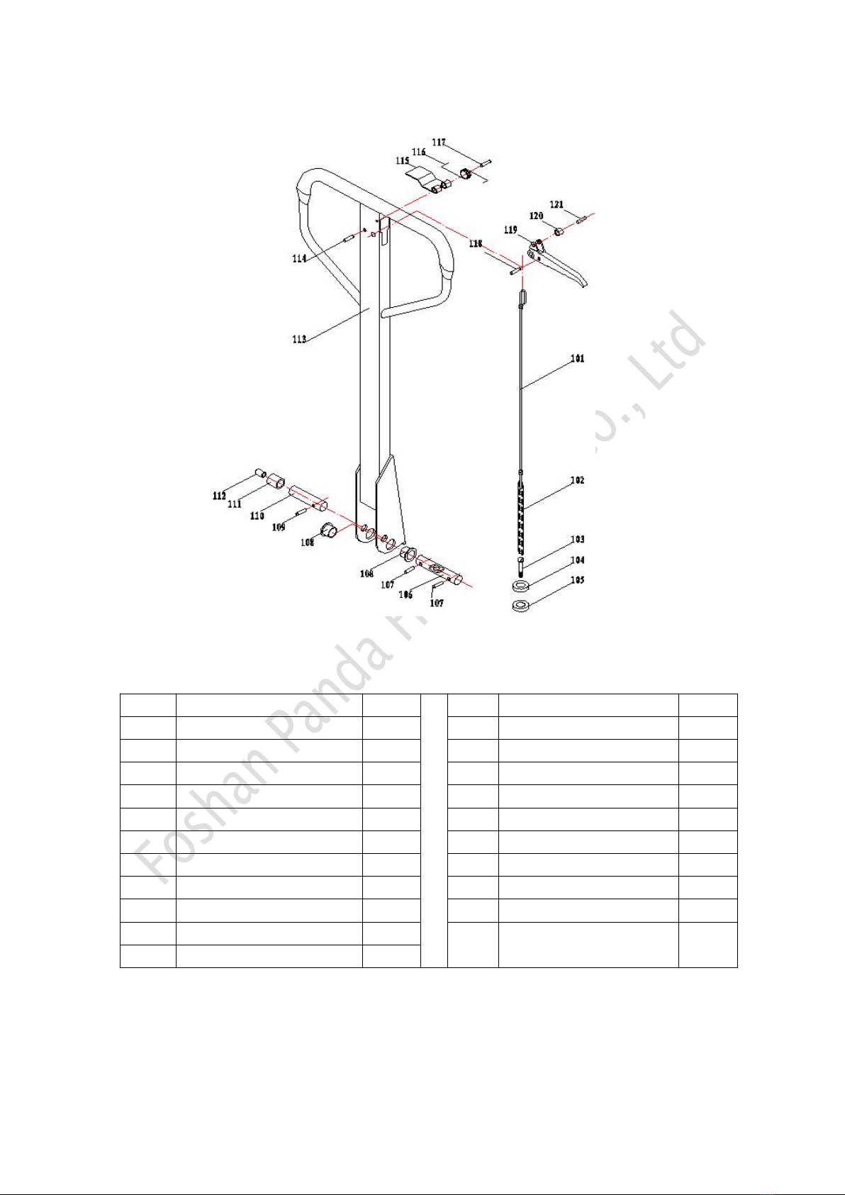
Parts of Handle welding prat
NO.
Description
Qty
NO.
Description
Qty
101
Pulling rod
1
112
Roller cover
1
102
Chain
1
113
Handle welding
1
103
Drop bolt
1
114
Elastic pin
1
104
Hexagonal nut
1
115
Return shrapnel
1
105
Metalloid nut
1
116
Return spring
1
106
Positioning bearing
1
117
Elastic pin
1
107
Elastic pin
2
118
Elastic pin
1
108
Cover
2
119
Control handle
1
109
Elastic pin
1
120
Handle wheel
1
110
Roller bearing
1
121
Elastic pin
1
111
Roller
1
6
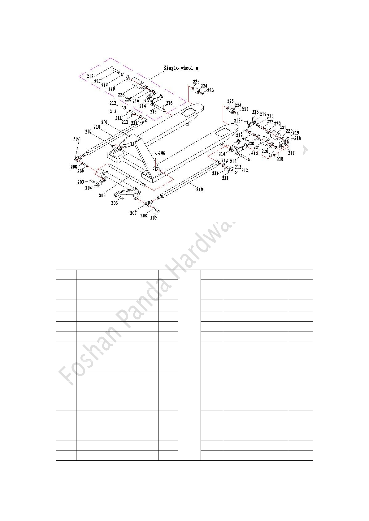
Parts of Body Frame
NO.
Description
Qty.
NO.
Description
Qty.
201
Body frame
1
219
Gasket
8
202
Inner hexagonal screw
1
220
Bearing
8
203
Connecting bearing
2
221
Front wheel
4
204
Lever frame
1
222
Front wheel bearing
4
205
Lever bearing
1
223
Hexagonal screw
2
206
Elastic pin
1
224
Climbing wheel
2
207
Fork ear
2
225
Metalloid nut
2
208
Washer for bearing
2
Single wheel part
209
Fork ear connector
2
210
Pushing rod welding
2
211
Open pin
4
214
Front wheel frame
2
212
Gasket
4
215
Positioning bearing
2
213
Pushing road connector
2
218
Elastic pin
2
214
Front wheel frame
2
219
Gasket
4
215
Positioning bearing
2
220
Bearing
4
216
Elastic pin
2
226
Single wheel
2
217
Double-wheel side board
4
227
Single wheel bearing
2
218
Elastic pin
8
218
Elastic Pin
4
7
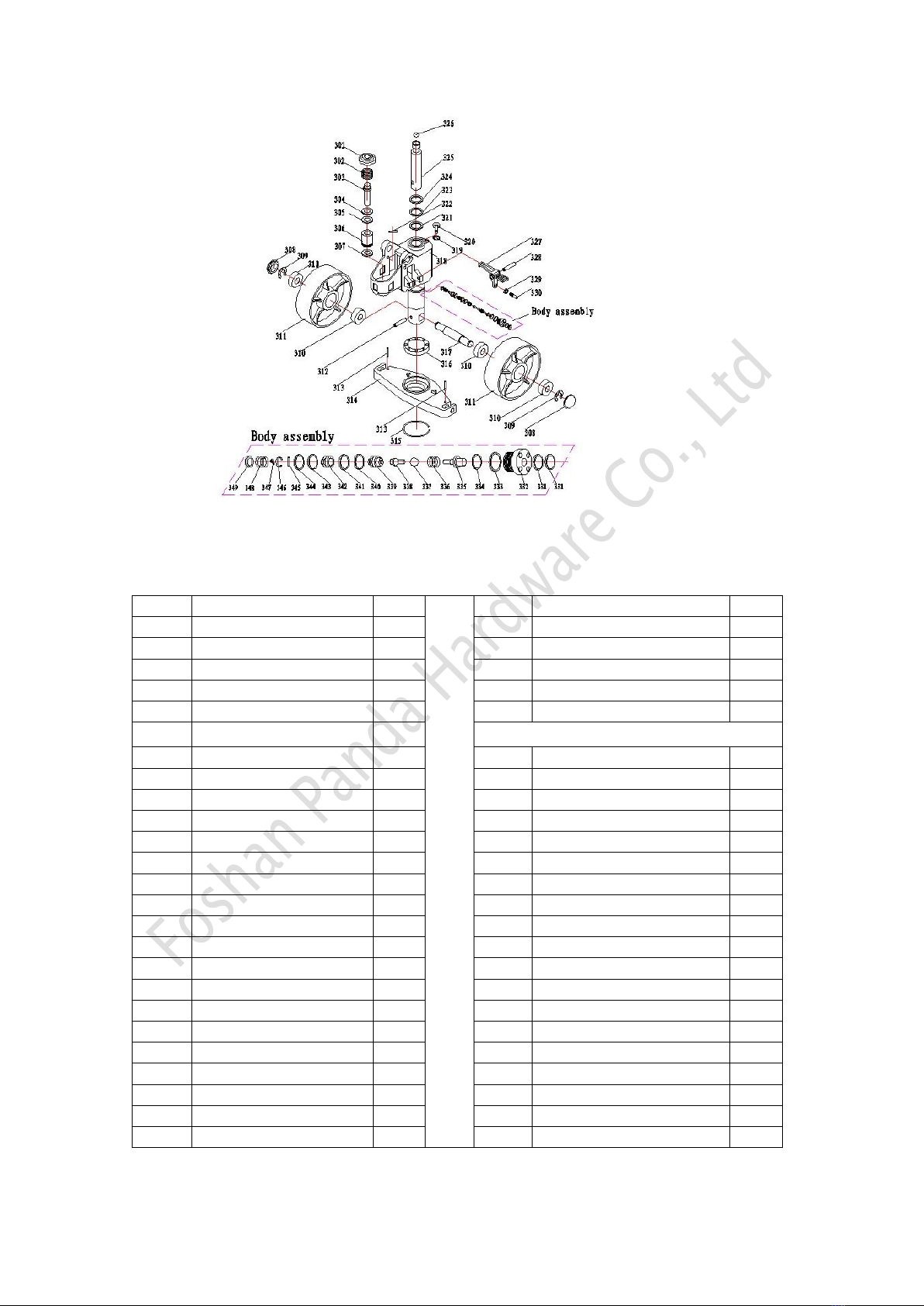
Parts of oil Pump
NO.
Description
Qty.
NO.
Description
Qty.
301
Spring gland
1
326
Steel ball
1
302
Pump core spring
1
327
Pedal control
1
303
Pump core
1
328
Elastic pin
1
304
Anti-dust ring
1
329
Nut
1
305
Sealing ring
1
330
Fasten screw
1
306
Small pump
1
Value body assembly
307
Copper sheet
1
331
"O"sealing ring
2
308
Anti-dust cover
2
332
Copper nut
1
309
Rand
2
333
"O"sealing ring
1
310
Bearing
4
334
"O"sealing ring
1
311
Rear wheel
2
335
Top rod
1
312
Elastic pin
1
336
Top rod spring
1
313
Elastic pin
2
337
Steel ball
1
314
Bearing board
1
338
High pressure
1
315
Check ring for bearing
1
339
Valve body connector
1
316
Pulling ball bearing
1
340
Cutting edge beaming
1
317
Rear wheel bearing
1
341
"O"sealing ring
1
318
Pump
1
342
High pressure valve body
1
319
Grouped gasket
1
343
Cutting edge beaming
1
320
Inner hexagonal screw
1
344
"O"sealing ring
1
321
Sealing ring
1
345
Elastic pin
2
322
Limit lever
1
346
Spring sheet
1
323
"O"sealing ring
1
347
Screw
1
324
Anti-dust
1
348
Valve core spring
1
325
Piston rod
1
349
Gland
1

8
BF Pump Explosive View
No.
Item Name
Spec
Qt
y
No
.
Item Name
Spec
Qty
No.
Item Name
Spec
Qty
1
Pump Out body 外
体
Iron Caste
1
13
Anti-dust ring
Φ18
泵芯防尘圈
Φ18*26*4.5
/6
1
25
Pressure Adjusting
Screw
调压螺钉
M10*1*8,5
1
2
Bonded washer
组合垫片
Φ10*1*9.5
1
14
Sealing ring
泵芯密封圈
Φ18*26*5
1
26
Bonded washer
组合垫
Φ10*2
1
3
Inner hexagonal
screw 内六角螺塞
M10*1
1
15
Limit Lever
限位杆
Φ7*95
1
27
Inner hexagonal
screw 内六角螺塞
M10*1*9.5
1
4
Piston rod
活塞杆
Φ31.5*263
1
16
Valve end Plug
Screw
组尼阀端螺塞
M20*1.5
1
28
Spring for Ejector pin
撞针弹簧
1.3*9.5*22
1
5
Sealing ring
活塞杆密封件
Φ31.5*41.5*6
1
17
Bonded washer
组合垫
Φ20
1
29
“O” Ring
O形密封圈
Φ6.9*1.8
2
6
“O” Ring
O形密封圈
Φ65*2.65
1
18
Pagoda Spring
宝塔弹簧
Φ0.7*20
1
30
Ejector pin
撞针
Φ10*52
1
7
Top Cover
顶盖
Φ31.5
1
19
Spool of orifice
Valve 阻尼阀芯
Φ4.80*19
1
31
Bonded washer
组合垫
Φ20*2
1
8
“O” Ring
O形密封圈
Φ31.5*3.55
1
20
Valve Body
组尼阀阀体
Φ4.9*11
1
32
Pedestal for Ejector
Pin 撞针座
M20*1.5*
18
1
9
Anti-dust Ring
活塞杆防尘圈
Φ31.5*39.5*5
*6.5
1
21
Steel Ball
钢球
SΦ5
1
33
Hexagon Nut
六角螺母
M6
1
10
Pump Plunger
泵芯(BF)
Φ18*97
1
22
Steel ball
钢球
SΦ6.35
1
34
Socket head cap
screw
开槽平端螺钉
M6*25
1
11
Spring Cover
弹簧压盖
Φ49*2*15
1
23
Cushion for Steel
ball 钢球垫
Φ8*8
1
35
Pedal Control
脚踏控制板
1
12
Plunger spring
泵芯弹簧
Φ5.5*外
48*115
1
24
Spring of Safety
Valve
安全阀弹簧
Φ2*8*16.5
1
36
Elastic Pin
弹性销
Φ8*52
1
This manual suits for next models
1
Table of contents


