Fostex FD-8 User manual

FD-8
Service Manual
Model
DIGITAL MULTITRACKER

SAFETY INSTRUCTIONS
Read instructions - All the safety and operating instruc-
tions should be read before the appliance is operated.
Retain instructions - The safety and operating instructions
should be retained for future reference.
Heed warnings - All warnings on the appliance and in the
operating instructions should be adhered to.
Follow instructions - All operating and use instructions
should be followed.
Water and Moisture - The appliance should not be used
near water - for example, near a bathtub, washbowl,
kitchen sink, laundry tub, in a wet basement, or near a
swimming pool, and the like.
Carts and Stands - The appliance should be used only
with a cart or stand that is recommended by the manufac-
turer.
An appliance and cart combination should be moved with
care. Quick stops, excessive force, and uneven surfaces
may cause the appliance and cart combination to over-
turn.
Wall or Ceiling Mounting - The appliance should be
mounted to a wall or ceiling only as recommended by the
manufacturer.
Ventilation - The appliance should be situated so that its
location or position does not interfere with its proper ven-
tilation. For example, the appliance should not be situ-
ated on a bed, sofa, rug, or similar surface that may block
the ventilation openings; or, placed in a built-in installa-
tion, such as a bookcase or cabinet that may impede the
flow of air through the ventilation openings.
Heat - The appliance should be situated away from heat
sources such as radiators, heat registers, stoves, or other
appliances (including amplifiers) that produce heat.
Power Sources - The appliance should be connected to a
power supply only of the type described in the operating
instructions or as marked on the appliance.
Grounding or Polarization - The precautions that should
be taken so that the grounding or polarization means of
an appliance is not defeated.
Power Cord Protection - Power supply cords should be
routed so that they are not likely to be walked on or
pinched by items placed upon or against them, paying
particular attention to cords at plugs, convenience recep-
tacles, and the point where they exit from the appliance.
Cleaning - The appliance should be cleaned only as rec-
ommended by the manufacturer.
Nonuse Periods - The power cord of the appliance should
be unplugged from the outlet when left unused for a long
period of time.
Object and Liquid Entry - Care should be taken so that
objects do not fall and liquids are not spilled into the en-
closure through openings.
Damage requiring Service - The appliance should be ser-
viced by qualified service personnel when:
A.
B.
C.
D.
E.
Servicing - The user should not attempt to service the ap-
pliance beyond that described in the operating instruc-
tions. All other servicing should be referred to qualified
service personnel.
REFER SERVICING TO QUALIFIED SERVICE PERSONNEL.
CAUTION
RISK OF ELECTRIC SHOCK
DO NOT OPEN
CAUTION: TO REDUCE THE RISK OF ELECTRIC SHOCK,
DO NOT REMOVE COVER (OR BACK).
NO USER-SERVICEABLE PARTS INSIDE.
TO PREVENT ELECTRIC SHOCK, MATCH
WIDE BLADE OF PLUG TO WIDE SLOT,
FULLY INSERT.
POUR ÉVITER LES CHOCS ÉLECTRIQUES,
INTRODUIRE LA LAME LA PLUS LARGE DE
LA FICHE DANS LA BORNE CORRE-
SPONDANTE DE LA PRISE ET POUSSER
JUSQU' AU FOND.
CAUTION:
ATTENTION:
The exclamation point within an equilateral
triangle is intended to alert the user to the
presence of important operating and mainte-
nance (servicing) instructions in the literature
accompanying the appliance.
The lightening flash with arrowhead symbol,
within an equilateral triangle, is intended to
alert the user to the presence of uninsulated
“dangerous voltage” within the product's en-
closure that may be of sufficient magnitude to
constitute a risk of electric shock to persons.
“WARNING”
“TO REDUCE THE RISK OF FIRE OR ELECTRIC SHOCK,
DO NOT EXPOSE THIS APPLIANCE TO RAIN OR MOIS-
TURE.”
1.
2.
3.
4.
5.
6.
7.
8.
The power supply cord or the plug has been damaged;
or
Objects have fallen, or liquid has been spilled into the
appliance; or
The appliance has been exposed to rain; or
The appliance does not appear to operate normally or
exhibits a marked changed in performance; or
The appliance has been dropped, or the enclosure
damaged.
9.
10.
11.
12.
13.
14.
15.
16.
17.

Parts marked with this sign are safety critical components. They must always be replaced with identical
components. Refer to the Fostex Parts List and ensure exact replacement.
CAUTION
TABLE OF CONTENTS
1. SPECIFICATIONS . . . . . . . . . . . . . . . . . . . . . . . . . . . . . . . . . .
2. CONTROLS, INDICATORS AND CONNECTORS . . . . . . . . . . .
3. SOFTWARE UPDATE . . . . . . . . . . . . . . . . . . . . . . . . . . . .
4. SERVICE MODE . . . . . . . . . . . . . . . . . . . . . . . . . . . . . . . . . . .
5. ERROR CODE LIST . . . . . . . . . . . . . . . . . . . . . . . . . . . . . . . .
6. INSTALLING 2.5" INTERNAL HARD DISK DRIVE . . . . . . . . .
7. EXPLODED VIEW, PCB ASSEMBLY AND PARTS LIST . . . . .
8. CIRCUIT DIAGRAMS . . . . . . . . . . . . . . . . . . . . . . . . . . . . .
Owner's manual : 8288419100 (for export model)
: 8288420000 (for domestic model)
Quick manual : 8288423100 (for export model)
: 8288424000 (for domestic model)
Service mode, error code list, exploded view, PCB assembly, parts list and circuit diagrams are given in this
manual to assist the service technician in maintaining the Model FD-8.
NOTES
The following accessories are supplied with FD-8 as the standard accessories.
*
*
Following is the packing material for the Model FD-8.
*
Carton, inner, FD-8 : 8228719000
Packing, side, L, FD-4/8 : 8228440000
Packing, side, R, FD-4/8 : 8228441000
FD-8
4
7
11
12
19
20
23
37
3

4
FD-8
1. SPECIFICATIONS
RECORD & REPRODUCE
Recording Medium External fixed / removable hard disk drive
Internal 2.5” E-IDE hard disk drive (option)
Standard SCSI-2 or better
Sampling Frequency 44.1 kHz
Quantization 16-bit linear
Emphasis Not available
Compression / Expansion Method A.D.A.C. (Advanced Digital Audio Acoustic Coding)
Recording Time (mono track min.)
MASTERING mode About 18 min. / 100 MB at maximum
NORMAL mode About 72 min. / 100 MB at maximum
Recording time will be limited up to 24 hours.
Number of Tracks 24 tracks (8 + 16 additional tracks)
Number of recording tracks 2 (8 when ADAT digital signal is input to DATA IN port)
Number of simultaneous recording tracks Depending on characteristics of recording medium
Number of simultaneous playback tracks 8
Recording Format FDMS-3
Recording Mode NORMAL mode (A.D.A.C., 8 + 16 tracks, default)
MASTERING mode (linear recording, 8 + 16 tracks)
BACKUP mode (for data archiving)
ELECTRICAL (0 dBV = 1 V)
• MIXER SECTION
Reference Input Level
MIC -50, -30 dBV
Impedance 20 kΩor more
LINE -10 dBV
Impedance 20 kΩor more
RECORDER IN -10 dBV
Impedance 20 kΩor more
AUX RTN -20 dBV
Impedance 8 kΩor more
DATA IN
Connector Square shape optical
Format IEC consumer optical standard IEC 958 Part 3
ALESIS Proprietary Multi Channel Optical Digital Interface
Reference Output Level
STEREO -10 dBV
Load impedance 10 kΩor more
AUX SEND -10 dBV
Load Impedance 10 kΩor more
MONITOR -10 dBV
Load impedance 10 kΩor more
HEADPHONE 20 mW at maximum (Load: 16 Ω)
50 mW at maximum (Load: 50 Ω)

FD-8
5
ELECTRICAL (continued)
DATA OUT
Connector Square shape optical
Format IEC consumer optical standard IEC 958 Part 3
ALESIS Proprietary Multi Channel Optical Digital Interface
SCSI DATA input / output
Connector D-SUB 25-pin
Protocol SCSI-2, unbalanced transfer method
Transfer type Asynchronous
Number of device to be connected 2
SCSI ID: 0 ~ 5 Recording / reproducing
SCSI ID: 6 Data backup
Fader / Knob Position at Reference Input / Output
MASTER fader
MONITOR knob
INPUT fader
Output Level
INPUT (1 ~ 8) →→
→→
→AUX SEND
INPUT (1 ~ 8) →→
→→
→MONITOR
Frequency Response
INPUT (1 ~ 8) →→
→→
→MONITOR 20 ~ 20 kHz +1, -3 dB (INPUT: -50 dBV)
20 ~ 20 kHz +1, -2 dB (INPUT: -10 dBV)
INPUT (1 ~ 8) →→
→→
→AUX SEND 20 ~ 20 kHz +1, -2 dB (INPUT: -10 dBV)
AUX RTN →→
→→
→MONITOR OUT 20 ~ 20 kHz +1, -2 dB (AUX RTN: -20 dBV)
AUX RTN →→
→→
→PHONES 80 ~ 20 kHz +1, -2 dB (AUX RTN: -20 dBV, at 20 mW /
16 Ωoutput)
EQ Characteristics
High (12 kHz) & Low (80 Hz) +15 dB ± 3 dB at “+15” position
-15 dB ± 3 dB at “-15” position
Mid (200 Hz ~ 5 kHz) +15 dB ± 3 dB at “+15” position
-15 dB ± 3 dB at “-15” position
At 8 ~ 9 position (AUX RTN : -20 dBV / 1 kHz, AUX RTN
VR: MAX. Adjust master fader for -10 dBV output at
STEREO OUT.)
At 2 ~ 5 position (AUX RTN : -20 dBV / 1 kHz, MON
SEL: ST+MON, ST. Adjust MONITOR knob for -10 dBV
output at MONITOR OUTPUT.)
At 7 ~ 8 position (INPUT: -10 dBV / 1 kHz, EQ GAIN: 0,
PAN: L (R). Adjust input fader for -10 dBV output at
STEREO OUT.)
-10 dBV +0, -2 dB (INPUT: -10 dBV / 1 kHz, EQ GAIN: 0,
PAN: L (R), AUX1, 2 VR: CH MAX, input fader: at 7 ~ 8
position.)
-10 dBV +1, -2 dB (INPUT: -10 dBV / 1 kHz, EQ GAIN: 0,
PAN: L (R), MON VR: MON MAX, MON PAN: L (R),
input fader: at 7 ~ 8 position.)
6
FD-8
ELECTRICAL (continued)
S / N
Distortion
Crosstalk 60 dB or more / 1 kHz
Click Noise
Power on / off -20 dBV p-p or less
Other switching -50 dBV p-p or less
MIDI Controlling Operation check should be executed using the test mode
with connecting the MIDI IN and OUT terminal.
• RECORDER SECTION
Frequency Response 20 ~ 20 kHz +1, -2 dB
Full Scale Output Level (Ref: -12 dB) +2 dBV ± 1 dB
Dynamic Range 88 dB or more
Total Harmonic Distortion 0.02 % or less (1 kHz, +2 dBV)
Channel Separation 80 dB or more (1 kHz, max. recording level)
S / N 88 dB or more (A-WTD.)
Power Consumption
JPN 15 W
Others 17 W
Specifications and appearance are subject to change without notice for product improvement.
INPUT
AUX RTN
-40 dBV
0 dBV
0 dBV
-10 dBV
-10 dBV
MONITOR
MONITOR
AUX SEND
MONITOR
PHONES
0 dBV
0 dBV
0 dBV
0 dBV
20 mW
100 ~ 10 kHz
100 ~ 10 kHz
100 ~ 10 kHz
100 ~ 10 kHz
1 kHz
0.05 % or less
0.05 % or less
0.05 % or less
0.05 % or less
0.10 % or less
LEVEL LEVEL
INPUT OUTPUT DISTORTIONFREQ. RANGE
INPUT
INPUT Σ8
Residual Noise
-50 dBV
-38 dBV
-10 dBV
+2 dBV
-50 dBV
-38 dBV
-10 dBV
+2 dBV
VR: MIN
AUX SEND
AUX SEND
AUX SEND
AUX SEND
MONITOR
MONITOR
MONITOR
MONITOR
PHONES
-10 dBV
+2 dBV
-10 dBV
+2 dBV
-10 dBV
+2 dBV
-10 dBV
+2 dBV
66 dB or more
78 dB or more
77 dB or more
89 dB or more
63 dB or more
75 dB or more
70 dB or more
82 dB or more
68 dB or more
80 dB or more
79 dB or more
91 dB or more
65 dB or more
77 dB or more
72 dB or more
84 dB or more
-75 dBV or less
LEVEL LEVEL UNWTD. AWTD.
INPUT OUTPUT S / N

FD-8
7
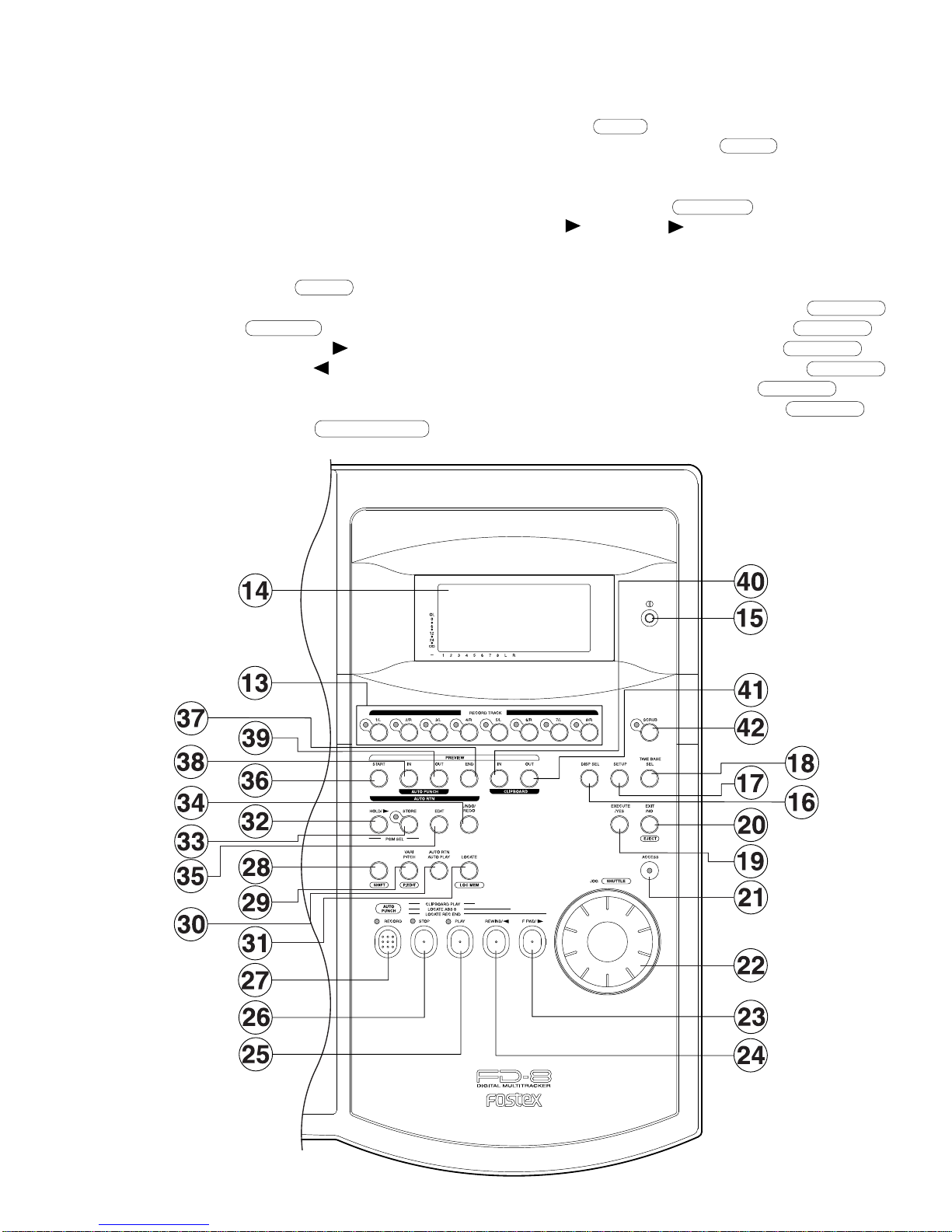
2. CONTROLS, INDICATORS & CONNECTORS
0
PAN
1
Rear Panel
Control Panel
Front Panel

8
FD-8
Control Panel (Mixer Section)
1. Input faders [1-8]
2. Input select switches
[INPUT SEL (INPUT/OFF/TRK)]
3. Panpot knobs [PAN (L/R)]
4. Monitor panpot knobs [PAN (MON L/MON R)]
5. Monitor level control knob [MON (INPUT/TRK)]
6. Equalizer control knobs
[EQ (HIGH/MID GAIN & SHIFT/LOW)]
7. AUX send knobs [AUX (AUX 1/AUX 2)]
8. AUX return knobs [AUX RTN (1, 2)]
9. Monitor master knob
[MONITOR SECTION (MASTER)]
10. Monitor select switch
[SELECTOR (L/R, L/R+MON, MON)]
11. Master fader [L/R]
12. Input level switches [LEVEL (H/M/L)]
0
1
FD-8
9
13. Record track select keys [RECORD TRACK (1/L,
2/R, 3/L, 4/R, 5/L, 6/R, 7/L, 8/R)]
14. LCD
15. Contrast adjustment knob
16. Display indication select key [DISP SEL]
17. Setup key [SETUP]
18. Time Base select key [TIME BASE SEL]
19. Execute/Yes key [EXECUTE/YES]
20. Exit/No key [EXIT/NO/ EJECT ]
21. Access LED [ACCESS]
22. JOG dial [JOG/SHUTTLE ]
23. Fast forward button [F FWD/ ]
24. Rewind button [REWIND/ ]
25. Play button [PLAY]
26. Stop button [STOP]
27. Record button [RECORD/ AUTO PUNCH ]
28. Shift key [ SHIFT ]
29. Vari Pitch key [VARI PITCH/ P.EDIT ]
30. Auto Return/Auto Play mode on/off key
[AUTO RTN/AUTO PLAY]
31. Locate key [LOCATE/ LOC MEM ]
32. Hold/ key [HOLD/ ]
33. Store key [STORE]
34. Undo/Redo key [UNDO/REDO]
35. Edit key [EDIT]
36. Auto Return Start key [AUTO RTN START/ PREVIEW ]
37. Auto Return End key [AUTO RTN END/ PREVIEW ]
38. Auto Punch In key [AUTO PUNCH IN/ PREVIEW ]
39. Auto Punch Out key [AUTO PUNCH OUT/ PREVIEW ]
40. Clipboard In key [CLIPBOARD IN/ PREVIEW ]
41. Clipboard Out key [CLIPBOARD OUT/ PREVIEW ]
42. Scrub key [SCRUB]
Control Panel (Recorder Section)

10
FD-8
Front Panel
Rear Panel
1. Monitor Out jacks [MON OUT L, R](RCA pin)
2. Stereo Out jacks [ST. OUT L, R](RCA pin)
3. AUX Send jacks 1, 2 [AUX SEND 1, 2](Phone)
4. AUX Return jacks 1, 2 [AUX RTN 1, 2](Phone)
5. Insert jacks 7, 8 [INSERT 7, 8](TRS Phone)
6. Balanced input connectors 7, 8 [INPUT 7, 8]
(Balanced XLR)
7. Recorder in jacks L, R [RECORDER IN L, R]
(RCA pin)
1. Input jacks [1, 2, 3, 4, 5, 6, 7, 8](Phone)
2. Headphone jack [PHONES](TRS Phone)
8. MIDI OUT jack [MIDI OUT](DIN 5-pin)
9. MIDI IN jack [MIDI IN](DIN 5-pin)
10. Punch in/out jack [PUNCH IN/OUT](Phone)
11. Data output jack [DATA OUT](OPTICAL)
12. Data input jack [DATA IN](OPTICAL)
13. SCSI connector [SCSI](D-SUB 25-pin)
14. AC IN connector
15. Power switch [POWER]

FD-8
11
3. SOFTWARE UPDATE
Same as the FD-4, the FD-8 software can be updated through the SCSI port. This means that unscrewing and opening up the
FD-8 top panel is not necessary to change the EPROMs. Please refer to the following explanation for correct software
updating procedures.
Updated software in a removable medium (e.g. floppy disk, zip disk, etc.) to be sent via airmail
Updated software as an attachment file to be sent via E-mail
There are two ways of sending the FD-8 updated software.
3-1. Method of Sending Software from Fostex Japan
1.
2.
3-2. Required Tools
IBM PC/AT compatible computer with SCSI board
Removable type SCSI drive
Cable between the removable type SCSI drive and the SCSI board
Cable between the removable type SCSI drive and the FD-8 (D-SUB 25-pin)
The following tools/equipment are required to update the FD-8 software.
3-3. Software Updating Procedures
Connect the removable type SCSI drive to the IBM PC/AT compatible computer SCSI port.
Insert the diskette to the removable type SCSI drive and format it by the computer on which Windows 95/98 is running.
Copy the updated software file to the removable type SCSI drive (diskette).
Set the removable type SCSI drive ID to 0 ~ 5 and connect to the FD-8 SCSI port.
Insert the diskette with updated software file. The FD-8 LCD display shows “No Disk”, “Initial..”, “name of drive (e.g.
ZIP 100)” and “FD8MOT” in order and comes to a standstill at the display below. Memorize the displayed ROM version
and date before updating the software.
Presuming that the updated software is correctly sent and is copied into your computer.
Pressing the EXECUTE/YES key would start updating the software. The display shows “Loading!”, “Writing!” and
“Initial..” in order and automatically returns to the above condition again. Check the displayed ROM version and date if
the software is correctly updated by comparing to the ones displayed in the above procedure 7.
Eject the diskette with updated software file by the press of STOP or EXIT/NO key and insert the diskette formatted by
the FD-8.
Confirm the software version by the Service Mode. For details, please refer to the section “4-2. Flash ROM/CPU version”.
CAUTION:
The diskette in which the updated software file is copied must be formatted by IBM PC/AT computer, not by Macintosh.
If something wrong happens while updating the software (e.g. A blackout occurred while updating the software.), the
FD-8 might not be able to boot up the system software inside the Flash ROM. In such a case, please refer to the section
“4-8. Flash ROM” (page 17).
The SCSI ID to be connected to the FD-8 must be selected to 0 ~ 5. The SCSI ID “6” is used for backing up purpose
exclusively. The SCSI ID “7” cannot be used by technical reasons.
1.
2.
3.
4.
1.
2.
3.
4.
5.
6.
7.
8.
1.
2.
3.
?
: blinking

12
FD-8
4. SERVICE MODE
There are various optional modes available in the FD-8 Service Mode. Please utilize them when servicing the unit.
Connect a SCSI device, insert the diskette formatted by the FD-8 and turn the power of SCSI device on.
After confirming that the access LED on the SCSI device is lit and then goes out, turn on the power of FD-8.
While holding down the STOP button and SHIFT key, press the SETUP key.
The way of putting the FD-8 into Service Mode is as follow.
4-1. Putting FD-8 into Service Mode
1)
2)
3)
As shown below, by rotating the jog dial C.W. or C.C.W., various optional modes will be displayed in addition to the
general SETUP menus. In order to select a certain optional mode, press the EXECUTE/YES key while its menu is
displayed.

FD-8
13
The example on the left indicates that the CPU version is
V2.00 and its programming date is August 4, 1998.
4-3. DA Test
This mode tests the signal flow from the DATA INPUT jack
to the D/A converter. A S/P DIF digital signal (Fs: 44.1kHz)
must be input to the DATA INPUT jack to execute this test.
Then, press the EXECUTE/YES key while “?” is blinking.
If the FD-8 is in a normal condition, “44.1kHz” and
“DIGITAL” will be lit solid. The odd (1, 3, 5, 7 and L) and
even (2, 4, 6, 8 and R) channels indicate the left and right
input level of S/P DIF digital signal fed to the DATA INPUT
jack respectively.
If the FD-8 is not in a normal condition, “DIGITAL” will
blink and the bargraph meter will not indicate any level.
4-2. Flash ROM & CPU version
This mode is used to check the Flash ROM and CPU versions
currently installed in the unit.
In order to check the version number, press the “EXECUTE/
YES” key while “?” is blinking as shown in the left.
The example on the left indicates that the Flash ROM version
is V1.00 and its programming date is September 5, 1998.
In this condition, by turning the jog dial C.W. or C.C. W.,
the CPU version can be checked.
: blinking
: blinking
: blinking
: blinking

14
FD-8
4-4. Display/Button Test
This mode tests if all the segments on the LCD display, LEDs
and buttons (switches) on the FD-8 top panel are correctly
working or not.
To execute this test, press the EXECUTE/YES key while
“?” is blinking.
If the FD-8 is in a normal condition, all the segments on the
LCD display will be lit solid and all the LEDs on the top
panel will start blinking.
If the FD-8 is not in a normal condition, faulty segments on
the LCD display and/or LEDs on the top panel will remain
unlit.
In this condition, if the EXECUTE/YES key is pressed one
more time, the Button Test can be executed.
The Button Test checks if each key/button and jog dial are
working properly or not. The display on the left indicates
that the RECORD button is pressed and held down. (“K”
stands for the Key and “J” the Jog dial.)
The display on the left indicates the condition when the jog
dial is turned C.W.
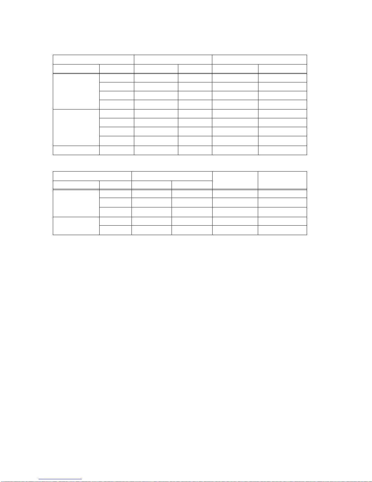
The table below shows the relationship between the key/
button/jog dial and the corresponding numbers appear on
the LCD display.
In order to quit the Button Test, turn the jog dial C.W. or
C.C.W. further after “J_20” or “J-19” is displayed
respectively.
Key/Button/Jog Dial No.
RECORD K01
STOP K02
PLAY K03
REWIND/ K04
F FWD/ K05
SHIFT K06
VARI PITCH/ P.EDIT K07
AUTO RTN/PLAY K08
LOCATE/ LOC MEM K09
HOLD/ K10
STORE K11
EDIT K12
Key/Button/Jog Dial No.
UNDO/REDO K13
EXECUTE/YES K14
EXIT/NO/ EJECT K15
AUTO RTN START K16
AUTO PUNCH IN K17
AUTO PUNCH OUT K18
AUTO RTN END K19
CLIPBOARD IN K20
CLIPBOARD OUT K21
DISP SEL K22
SETUP K23
TIME BASE SEL K24
Key/Button/Jog Dial No.
RECORD TRACK 1/L K25
RECORD TRACK 2/R K26
RECORD TRACK 3/L K27
RECORD TRACK 4/R K28
RECORD TRACK 5/L K29
RECORD TRACK 6/R K30
RECORD TRACK 7/L K31
RECORD TRACK 8/R K32
SCRUB K34
JOG DIAL (C.W.) J 00 ~ 20
JOG DIAL (C.C.W.) J -00 ~ -19
: blinking
?

FD-8
15
To start the Self Check mode, press the EXECUTE/YES
key when “?” is blinking.
As shown in the left, “SelfCheck”, “CurrentDr”, name of
connected SCSI drive (The example on the left shows that
the Magneto Optical drive MOS350 is connected to the FD-
8 SCSI port.) and “ATA Bus C (check)” appear on the FD-
8 LCD display in order.
If a 2.5" internal E-IDE hard disk drive is not installed in
the FD-8, the Self Check mode comes to a standstill at “ATA
Bus C (check)” test.
In order to continue the Self Check mode, press the
EXECUTE/YES key again.
4-5. Self Check
This mode automatically tests the following points in order.
• SCSI bus
• ATA (E-IDE) bus
• MIDI in/out circuit
• S/P DIF digital signal (44.1kHz)
• Vari-pitch circuit
• A/D and D/A circuit (Input Monitor)
<Cable Connection in “Self Check” Mode>
Continue to next page
In order not to form a MIDI signal loop,
connect the MIDI cable after putting the FD-
8 into the Service Mode.
CAUTION:
: blinking

16
FD-8
The followings are examples of error message when the FD-8 is not working properly.
• SCSI function • MIDI function
• Digital Signal in/out (Fs: 44.1kHz) • Vari-pitch function
4-6. Offset Display This mode determines if the offset value against a master
machine should be displayed or not when the FD-8 is
working as a slave machine.
In order to display the offset value, select the “MTC” time
base and the “REMAINING TIME” as DISP SEL key.
There might be a case that the percentage display does
not indicate “0.0%” exactly. This is caused by the
difference of internal clock between master and slave
machines, which is running independently.
The two-digit numbers displayed in the right of percentage
display (“05” in the left example) is only for software
programming purpose.
CAUTION:
1.
2.
If you would like to turn ON the offset display, press the
EXECUTE/YES key while “?” is blinking. (The default
setting is “off”.) Then, turn the jog dial C.W. to change the
display to “ON” and press the EXECUTE/YES key.
If the FD-8 is in a good condition, “Check OK!” will be
displayed and the FD-8 is automatically put into Input
Monitor mode with all the RECORD TRACK LEDs and
RECORD LED flashing. In this condition, if a signal is
applied to the FD-8 RECORDER IN (L, R) jacks, its level
can be monitored on the bargraph level meter.
To quit the Self Check mode, press the EXIT/NO key when
“Check OK!” is displayed.
From previous page
: blinking

FD-8
17
4-7. Initializing Disk This mode initializes an external SCSI device connected to
the SCSI port or a 2.5" E-IDE hard disk drive internally
installed. The disk drive currently connected can be
initialized.
4-8. Flash ROM This mode is used when copying the system software from
EPROMs to Flash ROM.
As mentioned in the section “SOFTWARE UPDATE”, the
FD-8 software inside the Flash ROM can be updated through
the SCSI port. However, if something wrong happens when
updating the software (e.g. A blackout occurred while
updating the software.), the FD-8 might not be able to boot
up by the system software inside the Flash ROM.
In this case, the following procedures must be taken.
Turn the switch S1 on the MAIN PCB assy to “EPROM” side.
Mount and solder the EPROM sockets to “U31” and “U32” on the MAIN PCB assy.
Plug the EPROMs into the sockets.
Turn on the power of FD-8.
1.
2.
3.
4.
In this condition, the FD-8 is booted up using the system software inside the EPROMs. The next procedures to take are as
follows.
Put the FD-8 into the Service Mode, select “FlashROM” and press EXECUTE/YES key. (“SURE?” is blinking.)
Press the EXECUTE/YES key one more time to copy the system software from EPROMs to Flash ROM.
Turn the switch S1 to “FLMEM” side.
In order to confirm that the FD-8 is booted up using the system software inside the Flash ROM, turn off the power,
disconnect the EPROMs and turn the power back on again.
After the confirmation, update the system software inside the Flash ROM through SCSI port again.
1.
2.
3.
4.
5.
CAUTION:
After pressing the EXECUTE/YES key, “SURE?” will start
blinking in the LCD display. In this condition, pressing the
EXECUTE/YES key one more time would initialize the
recognized disk drive.
This mode puts the disk back to the condition originally
formatted.
: blinking
?
: blinking
: blinking
If both the external SCSI drive and the internal 2.5” E-
IDE hard disk drive are connected at the same time, the
SCSI drive is given priority over the 2.5” E-IDE hard
disk drive and is recognized by the FD-8.
Up to 2 x SCSI drives can be connected to the FD-8. One
is for recording / reproducing (SCSI ID: 0 ~ 5) and the
other for exclusive backing up (SCSI ID: 6). Initializing
is possible on the SCSI drive (ID: 0 ~ 5) used for recording
/ reproducing only.
1.
2.

18
FD-8
4-10. Free Block Check
This mode is used to check the condition of the diskette
inserted into an external SCSI drive connected to the FD-8
or the internal E-IDE hard disk drive. (As mentioned before,
the SCSI drive has a priority unless the SCSI ID is set to
“6”.)
If the Free Block indicates a large number even after
formatting and no signal is recorded or recorded signals are
frequently skipped, the diskette / hard disk drive can be
judged to be in a bad condition.
4-11. Test 1
This Service Mode is exclusively designed for software
programming purpose. There is nothing to do with servicing
/ repairing the FD-8.
: blinking
: blinking

FD-8
19
5. ERROR CODE LIST
The chart below indicates the error code number and corresponding description. Since the error code list is basically
designed for our engineers to improve the software, the description is quite technical. If you find the FD-8 with one of the
error codes displayed, we encourage you to update the software first. In case updating the software does not solve the
problem, we would like you to inform us about details.
1 The FD-8 tries to access the address which does not exist.
3 SCSI drive does not boot up correctly when in SCSI access operation.
9When saving system region sector, its address is registered in Free_block File during Free block File
checking procedure.
10 Link_pointer which links Audio File indicates smaller address (out of region) than Link_File address region
in RAM.
11 Link_pointer indicates larger address (out of region) than Link_File address region in RAM.
12 “Pointer_addre” calculation of Link_Pointer is not correct.
14 Link_Pointer during recording/reproducing indicates smaller address (out of region) than actual Link_File
address region.
15 Link_Pointer during recording/reproducing indicates larger address (out of region) than actual Link_File
address region.
16 “Pointer_addre” calculation of Link_Pointer during recording/reproducing is not correct.
20 src_cash_load: Improper access of link address occurred while PASTE editing.
21 bak_cash_load: Program link during PASTE/MOVE editing is incorrect.
22 bak_cash_load: Imcompatibility problem occurred on program link during PASTE/MOVE editing.
30 Error when executing MOVE editing. Improper Link Pointer. Error in “bak_cash_load” function.
31 Error when executing MOVE editing. Improper Link Pointer. Error in “bak_cash_load” function.
32 Error when executing MOVE editing. Improper Link Pointer. Error in “bak_cash_load” function.
35 Backup_Save:Error occurred when saving data to SCSI device.
36 Backup_Load: Error occurred when loading data from SCSI device.
38 Displayed in Test Mode only. SCSI device cannot be recognized during initial test.
40 dis_cah_load: Improper access occurred when recording/reproducing.
41 dis_cah_load: Improper access occurred when recording/reproducing.
42 dis_cah_load: Improper access occurred when recording/reproducing.
45 get_non_des_block: Remaining disk capacity is insufficient.
52 non_des_cash_save_sub: Improper access occurred when recording/reproducing.
60 remake_free_block: There was improper access to program management region.
61 remake_free_block: There was improper access to program management region.
62 remake_free_block: Number of manageable events exceeds limit.
63 remake_free_block: There was improper access to program management region.
64 remake_free_block: There is an overlapping section in program management region.
96 There was improper access to program management region.
97 There was improper access to program management region when saving System File.
99 There was improper access when fading in/out.
FD-8 ERROR CODE LIST
DESCRIPTION
ERROR
CODE
20
FD-8
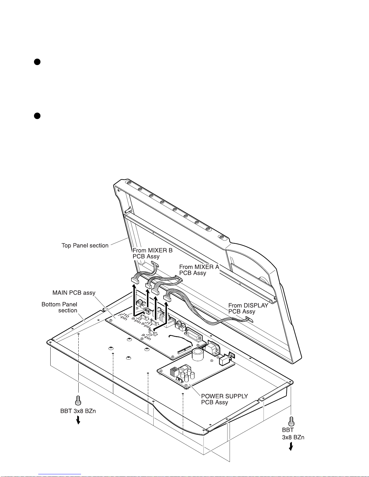
6. INSTALLING 2.5" INTERNAL HARD DISK DRIVE
The Model 9045 and a 2.5" E-IDE hard disk drive installing procedures are explained below.
• Bracket, HD, FD-4/8 (P/N: 8221234000) x 2
• Connector, PI, header, 50P, P2.0, A3E-50PA (P/N: 8245314000) x 1
• Cable, flat, 2P, L150 (P/N: 8276292015) x 1
• Cable assy, flat, 50P, P1.0, L180 (P/N: 8277465018) x 1
• 8 x screws (P 3 x 5 CZn)
Model 9045 Contents
Installing Procedures
Loosen 17 x screws (BBT 3 x 8 BZn) fixing the FD-8 Top Panel section to the Bottom Panel section.
Remove the following cables from the connectors on the MAIN PCB assy.
• 7-pin cable to the J10 (from MIXER A PCB assy)
• 9-pin cable to the J11 (from MIXER A PCB assy)
• 9-pin cable to the J3 (from MIXER B PCB assy)
• 9-pin cable to the J7 (from DISPLAY PCB assy)
1)
2)
Other manuals for FD-8
4
Table of contents
Other Fostex Recording Equipment manuals

Fostex
Fostex CR200 User manual

Fostex
Fostex D-90 User manual

Fostex
Fostex 280 User manual

Fostex
Fostex MR-16HD User manual

Fostex
Fostex X-15 Multitracker User manual

Fostex
Fostex DV-824 Configuration guide

Fostex
Fostex VF160EX User manual

Fostex
Fostex APPENDIX User manual

Fostex
Fostex DC-R302 User manual

Fostex
Fostex D-108 User manual


Popular Recording Equipment manuals by other brands


Coomber
Coomber Dance Combo 45790 Series Product instruction manual

M-system
M-system 75ET instruction manual

Russound
Russound CAA66 installation manual

EarthQuaker Devices
EarthQuaker Devices Data Gorrupter Operation manual

Studio Technologies
Studio Technologies 5205 user guide

JPS
JPS RSP-Z2 quick start guide