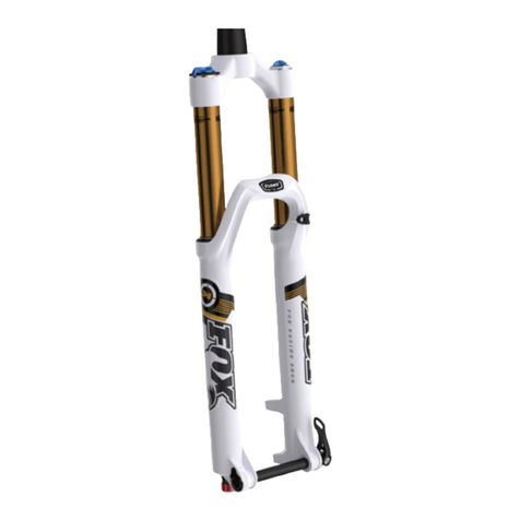
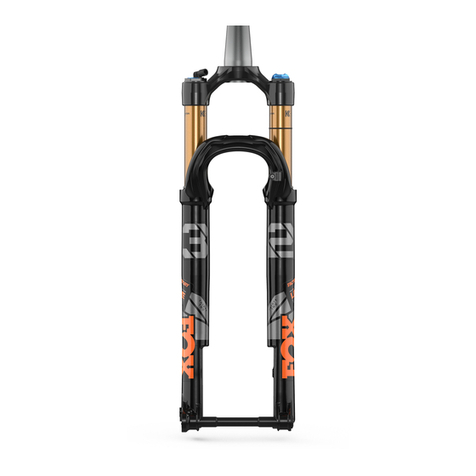
Fox 36 Talas 180 User manual

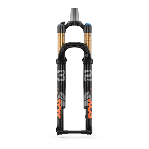
36 TALAS 180
Installing Your Fork | Before You Ride | Setting Sag | Adjusting Rebound | Adjusting High-Speed Compression | Adjusting Low-Speed Compression | Adjusting TALAS Travel | Service
Intervals | Important Safety Information
travel
•7.1 in./180 mm
TALAS 2-position travel adjust
system, 180-140 mm
model
features,
adjustments
Factory FIT RC2, 180: Kashima coated
or hard anodized upper tubes, 1.5"
tapered or 1 1/8" steerer, low-speed
compression, high-speed compression,
air spring pressure, rebound
Performance O/B R, 180: Hard
anodized upper tubes, 1.5" tapered or 1
1/8" steerer, air spring pressure,
rebound
lower leg 20QR thru axle system, post style disc
brake mounting
spring air
riding style AM, FR, DH
NOTE: This fork is designed to use the downhill brake system only. The disc brake caliper mounts directly to the fork leg and is positioned specifically for the use of
200-225 mm rotors.
Installing Your Fork
Be sure your fork is properly installed before proceeding. If your fork came pre-installed on your bicycle, continue to the next section.
Before You Ride
1. Check that your 20 mm axle pinch bolts and crown pinch bolts are properly adjusted and tightened.
2. Clean the outside of your fork with only mild soap and water, and wipe dry with a soft dry rag. NOTE: Do not use any solvents or de-greasers, as these products can
cause serious damage to paint and anodized parts (upper tubes, knobs, steerers).
Do not spray water directly on the seal/upper tube junction. Do not use a high pressure washer on your fork.
3. Inspect the entire exterior of your fork. The fork should not be used if any of the exterior parts appear to be damaged. Contact your local dealer or FOX Racing Shox for further
inspection and repair.
4. Check your headset adjustment. If loose, adjust it accordingly to your bicycle manufacturer's recommendations.
5. Check that all brake cables or hoses are properly fastened.
6. Test the proper operation of your front and rear brakes on level ground.
Setting Sag
To get the best performance from your fork, it is necessary to set the proper air spring pressure by adjusting sag. Generally, sag should be set to 15 – 25% of total fork travel.
1. Unscrew the center blue aircap in the middle of the TALAS travel adjusting topcap on top of the left fork leg, to expose the Schrader valve. TIP: Hold the TALAS lever steady
with one hand while unscrewing the aircap with the other.
2. Set the TALAS lever to the long travel position, turn off lockout and cycle the fork a few times. NOTE: For the best TALAS performance, always set sag in the long travel
position. Sag and spring rate will automatically readjust when you change to different travel settings.
3. Attach a FOX Racing Shox High Pressure Pump to the Schrader valve.
4. Pump your fork to the appropriate setting from the Suggested Air Spring Pressure Settings table below, then remove the pump.
5. Unless your fork already has a sag setting o-ring on an upper tube, install a zip tie to an upper tube. Slide the o-ring or the zip tie down against the scraper lip of the fork dust
seal.
6. Dressed to ride, position your bike next to a wall or table to support yourself. Without bouncing, mount your bicycle. Assume a normal riding position for at least 30 seconds,
allowing the suspension to fully settle.
7. Dismount your bike without bouncing downward, without further moving the o-ring or zip tie. Measure the distance between the seal and the zip tie. This measurement is your
sag value.
8. Compare your actual sag value to your target sag value in the Sag Setup table below.
If your sag measurement value is less than the Sag Setup table value, screw on the pump fitting, note the current air pressure setting and depress the black bleed-valve to
reduce the gauge pressure by 5 psi. Measure sag again and repeat this adjustment, if necessary.
If your sag measurement value is greater than the Sag Setup table value, screw on the pump fitting, note the current air pressure setting and pump to increase the gauge
pressure by 5 psi. Measure sag again and repeat this adjustment if necessary.
9. Screw the blue aircap back on.
10. Check your rebound adjustment; adjust it if necessary.
11. Rider
Weight
lbs.
12. Suggested Air Spring Pressure Settings
13. PSI
14. 180 mm
15. ≤125 16. 45
17. 125 - 135 18. 48
19. 135 - 145 20. 50
21. 145 - 155 22. 53
23. 155 - 170 24. 55
25. 170 - 185 26. 60
27. 185 - 200 28. 70
29. 200 - 215 30. 80
31. 215 - 230 32. 90
33. 230 - ≥250 34. 100

11. Rider
Weight
lbs.
12. Suggested Air Spring Pressure Settings
13. PSI
14. 180 mm
15. ≤125 16. 45
17. 125 - 135 18. 48
19. 135 - 145 20. 50
21. 145 - 155 22. 53
23. 155 - 170 24. 55
25. 170 - 185 26. 60
27. 185 - 200 28. 70
29. 200 - 215 30. 80
31. 215 - 230 32. 90
33. 230 - ≥250 34. 100
35.
36. Sag Setup
37. Travel 38. XC/Race FIRM 39. Freeride PLUSH
40. 170 mm (6.7") 41. 25.5 mm (1.00") 42. 42.5 mm (1.67")
43. 180 mm (7.1") 44. 27.0 mm (1.06") 45. 45 mm (1.77")
46.
47. Sag Troubleshooting
48. Symptom 49. Remedy
50. Too much sag 51. (+) air pressure in 5 psi
increments
52. Too little sag 53. (-) air pressure in 5 psi
increments
54. Excessive bottoming 55. (+) air pressure in 5 psi
increments
56. Harsh ride; full travel not
utilized
57. (-) air pressure in 5 psi
increments
Adjusting Rebound
The rebound knob (shown below) is located on the bottom of the right fork leg. Rebound controls the speed at which the fork extends after compressing. Turning the knob clockwise
slows down rebound; turning the knob counter-clockwise speeds up rebound. As a starting point, turn the rebound adjuster knob all the way clockwise (full in) until it stops, then
turn counter-clockwise (out) 9 clicks.
The rebound knob is protected by a black protective cap. Never ride your FOX 36 TALAS FIT RC2 without this black protective cap installed.
Knob
Setting
(clicks counter-
clockwise OUT
from fully
clockwise IN)
Setting
Descriptio
n
Tuning Tips Setup Tips
Full
in
Slow
Rebound
Too slow and your
fork will pack
down and ride
harsh.
If you increase your spring
rate or air pressure, you will
need to slow down your
rebound
9
(Factory
setting)
Average Rebound
Full
out
Fast Rebound
Too fast and you
will experience
poor traction and
wheel hop.
If you decrease your spring
rate or air pressure, you will
need to speed up your rebound
setting.
Adjusting Low-Speed Compression
Low-speed compression damping controls the influence of your forward and reverse weight shifts, and how your bike feels and performs when braking. This adjuster rotates to
stops at each end and has 24 clicks of adjustment. It is factory-set at 12 clicks out from the fully closed (clockwise) position.
Knob
Setting
(clicks counter-
clockwise OUT
from fully
clockwise IN)
Setting
Description Tuning Tips Setup Tips
24
Firm
Compression
Too firm and you
will experience
poor traction and
wheel hop.
Resists brake dive and keeps the
fork up in the travel. Too firm and
you may have poor traction in
loose conditions.
12 Average Compression (factory setting)
1
Soft
Compression
Too soft and your
fork will pack
down and ride
harsh.
Maximum wheel traction and bump
compliance. Too soft and you may
have excessive brake dive and a
wallow feel.
Adjusting High-Speed Compression

High-speed compression damping controls the force it takes to move the fork through its travel, or how quickly the wheel responds to a bump. This adjuster rotates to stops at each
end and has 24 clicks of adjustment. It is factory-set at 12 clicks out from the fully closed (clockwise) position.
Knob
Setting
(clicks counter-
clockwise OUT
from fully
clockwise IN)
Setting
Descriptio
n
Tuning Tips
24
Soft
Compression
Maximum wheel traction and bump compliance. If setting
is too soft, you may bottom often on square-edged hits
and G-outs.
12 Average Compression (factory setting)
1
Firm
Compression
Reduces bottom-out and provides maximum bump
absorption. If setting is too firm, you may experience a
harsh ride with poor traction and use too little of the
available travel.
Adjusting TALAS Travel
180 mm:
•7.10" (180 mm)
•5.50" (140 mm)
36 TALAS RC2 forks feature two externally adjustable travel choices, and these are easily selected with the TALAS travel adjusting topcap located on top of the left fork leg. Travel
options and direction are printed on the topcap.
NOTE: When changing travel, the TALAS system automatically adjusts to provide you with the appropriate linear air spring rate for each travel setting. There is no need
to change the air pressure in the TALAS air chamber after adjusting travel.
CAUTION: For safety reasons, adjust TALAS travel only when you're not riding the bike.
Service Intervals
To extend the service life of your FOX fork or shock, the best
product maintenance plan you can follow is cleaning the
product exterior after each and every ride or race. Use mild
soapy water, a very light pressure water spray to rinse, and
wipe dry with a clean, dry cloth.
CAUTION: Do not use any solvents or de-greasers, as these products can damage the shock's exterior finish or its anodized parts.
Do not spray water directly on the seal/upper tube junction.
Never use a high pressure washer on your FOX fork or
rear shock.
When dirt dries onto the fork upper tube or shock body, it will
chafe and damage the wiper seal. With a damaged seal, dirt
works its way into the fork or shock. Simple, periodic
maintenance can greatly extend the service life of your FOX
fork or shock.
TIP: If you ride in extreme conditions frequently (wet and muddy, downhill racing, winter riding, etc.), correspondingly the service intervals should be more frequent.
Rear Shocks
service item new each ride/
race
every 30
hours every 100 hours/annually
set sag X
check sag; reset if necessary X
set damping adjustments X
clean shock exterior with mild soap and water only; wipe dry
with soft towel X
air sleeve maintenance (FLOAT & DHX Air shocks) X
clean and inspect bushings & reducers X
suspension fluid service (must be performed by FOX Racing
Shox or Authorized Service Center)X
Air Spring Forks (All 32, 34, 36 FLOAT, TALAS, and DRCV)
service item new each ride/race every 30
hours
every 100
hours
set sag X
check sag; reset if necessary X
set damping adjustments X
clean exterior of fork with mild soap and water only; wipe dry
with soft towel X
inspect dropout thickness (9 mm) X
inspect bushings X
change oil in lower legs
Visit the FOXHelp service site for more service procedures
information.
X
change FLOAT fluid in air chamber of FLOAT forks. X
change FLOAT fluid in air chamber TALAS and DRCV forks. X
service damper: 32, 34, and 36 FIT; open cartridge (OC) and
Terralogic®X
Coil Spring Forks (36 VAN & 40)
service item new each
ride/race
every 30
hours
every
100
hours
set sag X
check sag; reset if necessary X
set damping adjustments X
clean exterior of fork with mild soap and water only; wipe dry
with soft towel X
inspect bushings X
change oil in lower legs
Visit the FOXHelp service site for more service procedures
information.
X
service damper: 36 RC2, 40 RC2 X
Important Safety Information
Forks
WARNING: DO NOT use FOX bicycle suspension products on any motorized bicycle, motorized cycle or motorized vehicle, or on any vehicle carrying more than one
operator/rider, such as a tandem bicycle. Any such misuse may overload the suspension and may result in failure of the suspension. Suspension failure may cause a
crash and result in property damage, SERIOUS INJURY, OR DEATH. Misuse of FOX suspension products voids all FOX warranties.
WARNING: FOX suspension products contain pressurized nitrogen, air, or both. Suspension misuse may cause property damage, SERIOUS INJURY, OR DEATH. DO NOT
puncture, incinerate or crush any portion of a FOX suspension product. DO NOT attempt to disassemble any portion of a FOX suspension product, unless expressly
instructed to do so by the applicable FOX technical documentation, and then ONLY while strictly adhering to all FOX instructions and warnings in that instance.
WARNING: Modification, improper service, or use of aftermarket replacement parts with FOX forks and shocks may cause the product to malfunction, resulting in
SERIOUS INJURY OR DEATH. Do not modify any part of a fork or shock, including the fork brace (lower leg cross brace), crown, steerer, upper and lower leg tubes, or
internal parts, except as instructed herein. Any unauthorized modification voids all warranties, and may cause failure of the fork or shock, resulting in SERIOUS INJURY
OR DEATH.
WARNING: Make sure that your wheels and wheel axles are securely fastened before riding, in accordance with the bicycle owner’s manual instructions. Either wheel
separating out of the bicycle frame can cause a loss of control, resulting in property damage, SERIOUS INJURY, OR DEATH.
WARNING: Before riding, verify that the brakes on your bicycle are installed and adjusted correctly in accordance with the brake manufacturer’s instructions. Improperly
installed and adjusted brakes may cause a crash and result in property damage, SERIOUS INJURY, OR DEATH.
WARNING: To avoid potential disc brake failure that could result in SERIOUS INJURY OR DEATH, the disc brake caliper mounting bolts must 1) always have 10-12 mm of
thread engagement with the fork and 2) be kept torque wrench tightened to the manufacturer’s specification. In all cases, the disc brake caliper mounting bolt
tightening torque level must never be less than the manufacturer’s torque specification, or exceed 90 in-lb torque.
WARNING: If mounting the bicycle in a carrier designed to hold a fork by its dropouts, avoid tilting the bicycle to either side, to avoid causing structural damage to the
fork. Be sure your fork is fastened securely with the quick-release mechanism (the 15QR, 20QR and 40 pinch axle, with the bike carrier’s thru-axle mount), and the rear
wheel is properly secured. If the bicycle ever tilts on or falls from a bicycle carrier, do not ride it until it is examined by a qualified bicycle service technician, Authorized
Service Center, or by FOX Racing Shox. A structurally damaged fork leg or dropout failure can cause a sudden loss of control, resulting in SERIOUS INJURY OR DEATH.
WARNING: When using a quick release mechanism to secure the front wheel into the FOX fork that is equipped with open dropouts and a disc brake system, be sure that
you adjust the quick release mechanism properly before closing it. A maladjusted quick release mechanism can lead to the sudden separating of the front wheel from the
bicycle at any time including when the front brake is applied. Front wheel separation may result in SERIOUS INJURY OR DEATH.
If your fork loses oil, tops out excessively or suddenly makes
unusual sounds, immediately stop riding and contact FOX
Racing Shox or an Authorized Service Center for inspection.
NOTE: Some sounds (such as oil flow, minor clicks, and spring rattle) are normal.
WARNING: A broken or malfunctioning damper cartridge may cause loss of vehicle control and result in SERIOUS INJURY OR DEATH.
CAUTION: Use a torque wrench to tighten the pinch bolts and axle on the FOX 40 to 19 in/lb. (2.15 Nm).
WARNING: Never attempt to remove or replace the steerer or upper tubes independently from the crown. Modifying the integrated crown, steerer, or upper tubes can
cause an assembly failure, resulting in a loss of control of the bicycle and SERIOUS INJURY OR DEATH.
WARNING: Never attempt to cut threads into the threadless steerers of FOX forks. Cutting threads into a threadless steerer can cause the steerer tube to fail
prematurely, resulting in a loss of control of the bicycle and SERIOUS INJURY OR DEATH.
WARNING: If the steerer tube has any nicks or gouges, the crown/steerer tube assembly must be replaced. A nick or gouge can cause the steerer tube to fail
prematurely, resulting in a loss of control of the bicycle and SERIOUS INJURY OR DEATH.
CAUTION: The total height of spacers used on a FOX steerer tube should never exceed 30 mm.
NOTE: FOX forks do not include reflectors for public road use. FOX forks are designed for use in competitive off-road riding and racing. Proper reflectors meeting the
Consumer Product Safety Commission's (CPSC) requirements should be installed if the fork will be used on public roads.
NOTE: After riding in salt-abundant areas (ocean coasts, desert salt flats, salted roads in winter), completely rinse off your bicycle to prevent corrosion.
Rear Shocks
If your shock ever loses oil or makes unusual noises, stop
riding and have the shock inspected by a qualified technician.
WARNING: A broken or malfunctioning shock may cause loss of vehicle control and result in SERIOUS INJURY OR DEATH.
Do not modify your bike frame or shock. Use only genuine
FOX Racing Shox parts.
WARNING: Modification, improper service or use of aftermarket replacement parts voids the warranty and may cause the shock to malfunction, resulting in loss of
vehicle control and SERIOUS INJURY OR DEATH.
Follow service maintenance recommendations. Shock service
should be performed by FOX Racing Shox in the USA or an
Authorized Service Center outside the USA. The exception is
air sleeve maintenance and mounting hardware service, which
can be performed by the consumer or a dealer.
FOX Racing Shox contain a nitrogen charge. Do not pry out the
white nylon (plastic) plug at the body eyelet end of the shock.
The charged portion of the shock should only be opened by a
FOX Racing Shox technician.
WARNING: Opening a nitrogen pressurized shock is dangerous and can result in SERIOUS INJURY OR DEATH.
On air shocks, the portion of the shock charged with nitrogen
does not need to be opened to perform air sleeve
maintenance.
WARNING: Attempting to pull apart, open, disassemble, or service a shock that is in a “stuck down” condition can result in SERIOUS INJURY OR DEATH.
A “stuck down” condition results from a failure of the dynamic
air seal located between the positive and negative air
chambers within the shock air sleeve, resulting with the
negative chamber retaining a higher air pressure than the
positive chamber. To test whether the shock is in fact “stuck
down”:
1. Remove the air cap and depress the Schrader valve to completely release air pressure from the positive air chamber of the shock.
2. If shock body retracts into the air sleeve near bottom out after air is released from positive air chamber, attach a FOX Racing Shox high pressure hand pump and pressurize the
shock to 250 psi/17 bar.
3. If the shock does not fully extend, it is in fact “stuck down”.
WARNING: Any improper servicing procedure with FOX air shocks in the “stuck down” condition can lead to SERIOUS INJURY OR DEATH. Contact FOX Racing Shox or an
Authorized Service Center for repair service.
After riding in salt-abundant areas (ocean coasts, desert salt
flats, salted roads in winter), FOX recommends completely
rinsing off your bicycle to prevent corrosion.
Copyright © 2012
FOX Factory Inc.
Table of contents
Other Fox Bicycle Accessories manuals

Fox
Fox FLOAT X2 Quick start guide

Fox
Fox 34 Talas 29 User manual

Fox
Fox Live valve Quick start guide

Fox
Fox LiveValve 32 Step Cast User manual

Fox
Fox 34 Float 29 User manual

Fox
Fox ELITE 2.5 Series User manual

Fox
Fox FLOAT SL User manual

Fox
Fox Live valve User manual

Fox
Fox DHX Air 5.0 User manual

Fox
Fox 36 Float 160 User manual