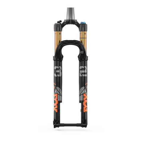
Fox LiveValve 32 Step Cast User manual

605-00-183 REV A
FOX FACTORY, INC. 2018 // 1.800.FOX.SHOX
915 DISC DRIVE. SCOTTS VALLEY, CA 95066 USA
TEL: 831.768.1100
OWNER’S GUIDE

TABLE OF CONTENTS
ENGLISH 3
FRANÇAIS 27
ITALIANO 51
DEUTSCH 75
ESPAÑOL 99
PORTUGUESE 123
CHINESE 147

3
CONGRATULATIONS!
Thank you for choosing a FOX suspension product for your bicycle. FOX suspension products are designed and
tested by the finest professionals in the industry, in Santa Cruz County, California, USA.
Follow the guidelines and instructions provided in this owner’s guide, so that you are able to properly set up, use,
and maintain your new FOX product.
More information and videos are available at http://www.ridefox.com/OwnersManuals, or call FOX US at
1.800.369.7469, email mtbservice@ridefox.com, or contact an Authorized International FOX Service Center at
http://www.ridefox.com/GlobalDistributors. If access to the Internet is not available to you, contact FOX to order a
paper copy of the online FOX owner’s manual for your product, free of charge.
WARNING AND SAFETY INFORMATION
The Live Valve system will come installed from the factory.
However, the battery must be charged and the system must
be calibrated before the first use. Improper calibration and/
or set up may cause the system to function improperly or
unexpectedly, which could cause a loss of control and lead to
SEVERE INJURY OR DEATH.
Improper cable routing of the Live Valve system may cause
cable damage, which could cause a loss of control and lead to
SEVERE INJURY OR DEATH.
DO NOT use a power washer or any high-pressure
cleaning methods.
DO NOT discard the battery’s rubber protective cover. This
protective cover is critical battery to protect the battery while
it is in storage or being transported away from the controller.
DO NOT discard the controller’s protective cover. This
protective cover is critical for protecting the main controller
when the battery is not connected (for example, during
charging o the bike). The main controller can sustain
damage through exposure to elements such as water and
debris and must be covered.
Begin with the fork and shock compression adjusters in the
SOFT (open) position.
FOX products should be installed by a professional bicycle
service technician, in accordance with FOX installation
specifications. Improperly installed forks can fail, causing the
rider to lose control resulting in SEVERE INJURY OR DEATH.
Modification or alteration of a FOX product can cause product
failure resulting in SEVERE INJURY OR DEATH. Never modify
or alter ANY part of a FOX product (including lower leg cross
brace, crown, steerer, upper tubes, lower leg, air can, seat post,
air volume spacers, internals, axle slit shims, axle adapters, or
any other parts).
FOX bicycle suspension products may also be used on pedal-
assisted motorized cycles or motorized vehicles that produce
less than 250 watts of power. DO NOT use FOX Bicycle
suspension products on vehicles that produce 250 watts of
power or more.
FOX E-BIKE OPTIMIZED suspension products may be used on
motorized cycles or motorized vehicles producing between
250-500 watts of power. DO NOT use any FOX bicycle
suspension product on any pedal-assisted motorized cycle or
motorized vehicle that produces more than 500 watts
of power.
DO NOT use any FOX bicycle suspension products or FOX
E-BIKE OPTIMIZED suspension products on any pedal-
assisted motorized cycle or motorized vehicle that produces
more than 500 watts of power. DO NOT use any FOX bicycle
suspension product on any throttle-equipped
motorized vehicle.
Misuse of FOX suspension products may cause the suspension
to fail, resulting in property damage or SERIOUS INJURY OR
DEATH, and void the warranty.
DO NOT use FOX bicycle suspension products on any vehicle
carrying more than one operator or rider, such as a tandem
bicycle or heavy utility bicycle.
Do not remove or replace the steerer tube. This could result in
the loss of control of the bicycle and SEVERE INJURY
OR DEATH.
Never attempt to remove or replace the steerer or upper
tubes independently from the crown. Modifying the
integrated crown, steerer, or upper tubes can cause an
assembly failure, resulting in a loss of control of the bicycle
and SEVERE INJURY OR DEATH.
Do not cut the steerer more than three (3) mm below the
uppermost installed part. If the steerer length is mistakenly
cut too short, it MUST BE REPLACED! Using a fork with
clamped steerer engagement that is too short can lead to
sudden fork failure, which can cause loss of control of the
bicycle resulting in SEVERE INJURY OR DEATH.
If the steerer tube has any nicks or gouges that can be felt
with your fingernail, the crown/steerer tube assembly must
be replaced. A nick or gouge can cause the steerer tube to
fail, resulting in a loss of control of the bicycle and SEVERE
INJURY OR DEATH.
Never attempt to cut threads into the threadless steerers of
FOX forks. Cutting threads into a threadless steerer can cause
the steerer tube to fail, resulting in a loss of control of the
bicycle and SEVERE INJURY OR DEATH.
ENGLISH

4
Never use more than 30 mm of height of steerer stem spacers
under the steerer stem, as this condition can cause the steerer
tube to fail, causing a loss of control resulting in SEVERE
INJURY OR DEATH.
Never allow things such as cable or cable housing to come in
contact with the steer tube of a fork. If your bike has internal
cable and cable housing routing, please consult your bicycle
manufactures owner’s guide for safety instructions. Cable
and/or cable housing that comes in contact with a steer tube
can cause the steerer tube to fail, resulting in a loss of control
of the bicycle and SEVERE INJURY OR DEATH.
Cable housing contacting the fork crown will cause abrasion
damage to the crown over time. If contact is unavoidable, use
vinyl tape or similar protection to cover the point of contact.
The FOX warranty does not cover abrasion damage to the
FOX fork crown.
Improper service, or use of non-FOX replacement parts with
FOX forks and shocks may cause the product to malfunction,
resulting in SEVERE INJURY OR DEATH.
As dirt and debris can accumulate between the fork axle
openings, always check and clean these areas before
installing the wheel. Improper hub and axle installation can
result in SEVERE INJURY OR DEATH.
Never use a power washer to clean your FOX product.
If your fork loses oil, tops or bottoms out excessively, or
makes unusual noises, do not ride the fork and immediately
contact FOX or an Authorized FOX Service Center for an
inspection or repair service.
Follow your brake manufacturer’s installation instructions
for proper installation and adjustment of the brake system.
Failure to properly install and adjust your brakes can lead to
a loss of control of the bicycle, which can result in SEVERE
INJURY OR DEATH.
Your fork or shock may fail under conditions that cause
bending and/or breaking to any part of the fork or shock. Any
condition that causes a loss of air and/or oil, such as a collision
or extended periods of non-use, may also cause your fork or
shock to fail. A damaged and/or leaking fork or shock can fail,
resulting in a crash and SEVERE INJURY OR DEATH. If you
suspect your fork or shock has been damaged, stop riding
immediately and contact FOX for inspection and repair.
A fork-mounted carrier may cause damage to the fork
legs and/or dropouts, especially in cases where the fork is
side-loaded and/or when the rear wheel is not secured in the
carrier. Damaged fork legs and/or dropouts can fail, resulting
in a crash and SEVERE INJURY OR DEATH. If you suspect
your fork has been damaged, contact FOX for inspection
and repair.
Never attempt to pull apart, open, disassemble, or service
a FOX shock that is in a “stuck down” condition. A “stuck
down” condition results from a failure of the dynamic air seal
(located between the positive and negative air chambers
within the non-EVOL shock air sleeve), resulting with the
negative chamber retaining a higher pressure than the
positive chamber. To test whether the shock is in fact
“stuck down”:
• Remove the air cap and depress the Schrader valve,
to completely release air pressure from the positive
chamber of the shock.
• If the shock body retracts into the air sleeve near
bottom-out after the air is released from the positive
chamber, attach a FOX high-pressure pump and
pressurize the shock to 250 psi (17 bar).
• If the shock does not fully extend, it is in a “stuck
down” condition.
• Any attempt to service FOX air shocks in the “stuck
down” condition can lead to SERIOUS INJURY OR
DEATH. Contact FOX or an Authorized Service Center
for repair.
WARNING AND SAFETY INFORMATION

5
LIVE VALVE PARTS DIAGRAM
Live Valve Fork
Front Sensor
Mounted to Rear of
Fork Brace
Live Valve Shock
Main Controller
and Battery Pack
Rear Sensor

6
FORK INSTALLATION
1. Remove the existing fork from the bicycle. Remove the crown race from the old fork. Measure the steerer
tube length of the old fork and transfer this measurement to your new FOX fork’s steerer tube.
If you don’t have an existing fork, measure the headset stack height (headset parts and frame head
tube) and refer to your stem manufacturer’s instructions to be sure there will be enough clamping
surface for the stem.
2. Mark the steerer tube and cut it to the proper length.
3. Install the headset. Always use a new threadless headset and follow the headset
manufacturer’s instructions.
4. Install a 39.8 mm crown race for 1 1/2 in. steerer tubes and a 29.9 mm crown race for 1 1/8 in. steerer
tubes. Use a crown race setter to install the crown race firmly against the top of the crown.
5. Use a star-fangled nut installation tool to install the star nut 4-10 mm below the top of the steer tube.
6. Install the fork onto the bicycle. Install the headset bearing parts and stem in accordance with the
headset manufacturer’s instructions, and adjust the headset preload accordingly until you feel no
excessive play or bearing drag. Tighten the stem clamping bolts to the stem manufacturer’s torque
specifications.
7. Install the brakes according to the brake manufacturer’s instructions.
Maximum rotor size for 32 Step Cast 27.5 in. forks is 180 mm. All other
FOX forks can use up to a 203 mm rotor (including Step Cast 29 in. forks).
8. Route the front disc brake hose or cable housing to the inside of the
lower leg, and through the supplied disc brake housing guide. Use a
torque wrench to tighten the disc brake hose guide screw to
0.9 Nm (8 in-lb).
WARNING
Prior to any cutting, consult your headset and stem manufacturer’s
instructions to ensure that you have enough steerer tube length for
clamping the steerer and stem. Improper installation can lead to a
separation of the stem from the steerer, resulting in a loss of control of
the bicycle and SEVERE INJURY OR DEATH.
10-12 mm thread
engagement
WARNING
The disc brake caliper mounting bolts must have 10-12 mm of
thread engagement with the fork. Use a torque wrench to tighten
the caliper mounting bolts to the disc brake manufacturer’s
specification, but do not exceed 10.2 Nm (90 in-lb). Improper
installation can lead to brake failure, resulting in a loss of control
of the bicycle and SEVERE INJURY OR DEATH.

7
15 MM QUICK RELEASE INSTALLATION
Wheel installation is identical for both the 15x100 mm and 15x110 mm quick release (QR) axles.
1. Install the front wheel into the fork dropouts. Slide the axle through the non-drive side dropout and hub.
2. Open the axle lever.
3. Turn the axle clockwise 5-6 complete turns into the axle nut.
4. Close the lever. The lever must have enough tension to leave an imprint on your hand.
5. The closed lever position must be between 1-20 mm in front of the fork leg.
6. If the lever does not have enough tension, or has too much tension when closed at the recommended
position (1-20 mm in front of the fork), see the next section for adjustment instructions.
WARNING
Use hand pressure only. Never use any tool to tighten the quick release lever. Over-tightening the
levers can damage the axle or fork dropouts, leading to a sudden failure with one or more of these
components, resulting in SEVERE INJURY OR DEATH. Failure to secure the axle properly can cause
the wheel to become detached from the bicycle, resulting in SEVERE INJURY OR DEATH.
1-20 mm
ADJUST THE QUICK RELEASE
1. Note the axle number, which is the number at
the indicator arrow.
2. Use a 2.5 mm hex wrench to loosen the axle
nut keeper screw approximately 4 turns, but do
not completely remove the screw.
3. Move the quick release lever to the open
position and unthread the axle approximately
4 turns.
4. Push the axle in from the open lever side. This
will push the axle nut keeper out and allow you
to rotate it out of the way.
5. Continue to push on the axle and turn the axle
nut clockwise to increase the lever tension, or
counter-clockwise to decrease the lever tension.
6. Return the axle nut keeper into place and
torque the bolt to 0.9 Nm (8 in-lb).
7. Repeat the axle installation instructions to
verify proper installation and adjustment.
Axle nut keeper screw
Axle nut keeper
Axle nut
Axle number
Indicator arrow

8
KABOLT INSTALLATION
Wheel installation is identical for both the 15x100 mm
and 15x110 mm Kabolt axles.
1. Install the front wheel into the fork dropouts. Slide the
Kabolt axle through the non-drive side dropout and hub.
2. Use a 6 mm hex wrench to torque the Kabolt
axle (clockwise) to 17 Nm (150 in-lb).
TIRE CLEARANCE TEST
1. Release all air pressure from the fork by depressing the Schrader valve.
2. Compress the fork completely.
3. Measure the distance from the edges of the inflated tire to the crown, fork brace, and
steerer. There must be AT LEAST 8.5 mm of clearance around the entire tire.
4. Add air pressure to your desired setting using a FOX high-pressure pump. Set the sag
according to instructions online at www.ridefox.com.
5. You must repeat this test EVERY time you change tires or rims.
WARNING
FOX forks may contain high air pressures. Release ALL air pressure from the main
air chamber before disassembly. Failure to do so may result in parts or fluids
ejecting from the fork, which can cause SEVERE INJURY OR DEATH.
WARNING
Failure to leave at least 8.5 mm of clearance between the edges
of the inflated tire and the crown, fork brace, and steerer may
cause the tire to jam against the crown when the fork is fully
compressed, which can result in SEVERE INJURY OR DEATH.
WARNING
Do not exceed maximum air pressure:
32 FLOAT maximum air pressure is 140 psi.
34 FLOAT maximum air pressure is 120 psi.
36 FLOAT maximum air pressure is 120 psi.
Minimum air pressure is:
40 psi for all FLOAT forks.
Pressure measured at an ambient
temperature of 70-75˚F. Normal operating
temperature range for FOX products is
20-140˚F.
> 8.5 mm8.5 mm

9
AIR SPRING VOLUME SPACERS
Changing volume spacers in FOX FLOAT forks is an easy internal adjustment that allows you to
change the amount of mid stroke and bottom out resistance. If you have set your sag correctly
and are using full travel (bottoming out) too easily, then you could install one or more spacers
to increase bottom out resistance. If you are not using full travel, then you could remove one or
more spacers to decrease bottom out resistance.
1. Remove the air cap.
2. Release all air pressure from the fork by depressing the Schrader valve.
3. Carefully unthread the topcap from the fork with a 6-point chamfer-less 26 mm socket
(for 36 Forks, use a 6-point chamfer-less 32 mm socket).
4. Pull up to remove the topcap assembly from the fork crown.
5. Slide the air volume spacer or spacers horizontally to install or remove them from the topcap.
6. Reinstall the topcap assembly into the fork crown and tighten to 24.8 Nm (220 in-lb) with
a 6-point chamfer-less 26 mm socket (for 36 Forks, use a 6-point chamfer-less
32 mm socket).
7. Add air pressure to your desired setting using a FOX high-pressure pump. Set the sag
according to instructions online at www.ridefox.com.
WARNING
FOX forks may contain high air pressures. Release ALL air pressure from the main air
chamber before disassembly. Failure to do so may result in parts or fluids ejecting
from the fork, which can cause SEVERE INJURY OR DEATH.
WARNING
Do not exceed the maximum number of volume spacers for your fork. This can
damage your fork. Find volume spacer information online at www.ridefox.com.

10
REAR SHOCK INSTALLATION
WARNING
Rear shock setup and configuration varies greatly between dierent bicycle manufacturers. Be sure to
refer to the owner’s manual for your bicycle. FOX products should be installed by a qualified bicycle
service technician, in accordance with FOX installation specifications. Improperly installed shocks can fail,
causing the rider to lose control, resulting in SERIOUS INJURY OR DEATH.
If you are installing your shock on a bike for which the shock was not original equipment, follow the steps
below to ensure proper clearance before riding.
AIR SHOCKS
1. Install the shock onto your frame according to your frame manufacturer’s instructions.
2. Remove the air cap, attach a shock pump, then SLOWLY release all air out of the main air chamber.
3. Slowly compress the suspension through its entire travel.
4. Check that the shock does NOT contact any portion of your frame or linkage as it cycles through
its travel.
5. Set the sag according to instructions online at www.ridefox.com.
EVOL AIR SLEEVE
ADDING AIR PRESSURE
Equalize the positive and negative air chambers by slowly compressing the shock through 25% of its travel
10-20 times after every 50 psi addition.
Failure to equalize the chambers can result in greater pressure in the positive air chamber than the
negative chamber. If the shock feels very sti and is in the topout position, compress the shock until you
hear or feel air transfer. Hold the shock in this compressed position for a few seconds.
RELEASING AIR PRESSURE
Release air slowly so the air from the negative chamber can also be released through the Schrader valve.
Releasing the air pressure too quickly can cause the negative chamber to have more pressure than the
positive chamber. If the shock is compressed into its travel and does not fully extend, add air pressure
until the shock extends, then slowly compress the shock through 25% of its travel 10-20 times.
WARNING
Do not use more than the FOX Factory specified quantity of volume spacers
for your shock absorber.
Do not exceed maximum air pressure:
EVOL air shocks have a maximum air pressure of 350 psi.
Minimum air pressure is:
50 psi for all air shocks.
Pressure measured at an ambient temperature of 70-75˚F. Normal operating
temperature range for FOX products is 20-140˚F.

11
ROUTE AND CONNECT THE CABLES
1. The front sensor cable has an audio jack cable end.
Route the front sensor cable so there are no tight
bends or obstructions from other cables.
2. Insert the front sensor cable into the front sensor
until you hear a click.
3. Make sure to orient the sensor connector on top
of the brake line and closest to the fork. Snap the
sensor clip to brake line first, and then snap it to the
sensor connector. There must be a strain relief loop
in the cable so it can move freely as the fork goes
through its travel.
STRAIN RELIEF LOOP

12
4. Install a zip tie around the center of the sensor clip.
5. Install a cable clip near the head tube on the front
sensor cable and another cable.
6. Remove the fork air cap. Use a hex wrench to release
all of the air from the air valve. Compress the fork to
bottom out and make sure the strain relief loop in the
cable allows the cable to move freely as the fork goes
through its travel.
NOTICE
Do not install any zip ties anywhere between this cable clip
and the sensor clip. The front sensor cable is equipped with a
quick release to prevent cable damage in the event of a crash.
This quick release will not function if the sensor cable is zip
tied anywhere between this cable clip and the sensor clip.

13
7. The front solenoid cable has DC jack cable end. Route
the front solenoid cable so there are no tight bends or
obstructions from other cables.
8. Insert the front solenoid cable into the front solenoid.
9. Compress the fork to bottom out. Make sure there is
a strain relief loop in the cable and that it can move
freely as the fork goes through its travel. Check to
make sure the cable is oriented to clear the fork brace
without pinching.

14
10.Install a cable clip near the head tube to attach the
front solenoid cable to the other cable. Compress
the fork to bottom out once again and check that
all cables move freely as the fork goes through its
travel. Adjust the position of the cable clips
as needed.
11. Turn the handlebars all the way to the right and left.
Check that all cables move freely with no excessive
tension, obstruction or tight bends.
12. Verify that the rear sensor clears the rear rotor and
is securely attached.

15
13. Dierent frames will require dierent routing for
rear sensor and clip attachments. In general, it’s ok
to clip the cables anywhere in the rear.
14. Install the cable clip around the shock reservoir.
Note there is more than one position for the cable
and reservoir.

16
CHARGE AND INSTALL THE BATTERY
The battery can be charged on or o the bike. To display the battery charge level, press the Power button
while the battery is connected to the main controller. Battery level is indicated by 1-5 LED lights (when 5
LED lights illuminate, the battery is fully charged).
1. Remove the cover over the charging port of the battery.
2. Insert the provided micro USB cable into the USB port of the battery. Then connect the USB cable to
any USB charging port.
3. The red charging LED will illuminate. The red charging LED will turn o when battery charging is
complete (approximately 2 hours).
4. Reinstall the cover over the charging port of the battery.
5. Remove the protective cover from the main controller mounted on the bicycle frame and store it in a
safe place.
6. Remove the rubber cover from the battery and store it in a safe place.
7. Install the battery onto the main controller. Align the pins on the main controller with the port in the
battery. Attach the two buckles into the grooves of the battery and click them closed.
CALIBRATE THE SYSTEM
Verify that the professional bicycle mechanic has completed the calibration sequence correctly.
This step is critical to ensuring the system responds appropriately to terrain. Calibration only needs
to take place once, unless components are replaced, in which case the system requires
recalibration.
The LIVE Valve system will not function properly unless it is calibrated according to the sequence
below. It is ok to repeat calibration.
1. Press the Power button to turn the system on.
2. Make sure the bike is upright, still, and on a level surface.
3. Press and hold the Setting Selector button for 15 seconds.
4. Release the Setting Selector button once the red OFF LED illuminates.
5. Once a green LED illuminates, press the Power button once and release it.
6. A green LED will flash 3 times to indicate the calibration process is complete.
NOTICE
Do not discard the controller’s protective cover. This protective cover must
be transferred to the customer because is critical for protecting the main
controller when the battery is not connected (for example, during charging
o the bike). The main controller can sustain damage through exposure to
elements such as water and debris and must be covered.
NOTICE
Do not discard the battery’s rubber protective cover. This protective cover
must be transferred to the customer because is critical to protect the
battery while it is in storage or being transported away from the controller.

17
LIVE VALVE SETTING
LIVE Valve has five programmed settings that can be selected to control how
sensitive the system feels. For example, setting five will take a slightly bigger
bump or landing to open compared to setting four.
We recommend you start in setting two.
1. If the system is not already on, press the Power button once.
2. Press and release the Settings Selector button once to determine the
existing setting.
3. Quickly press the Settings Selector button again to toggle through the
five settings.
4. When the LED lights turn o, this indicates the new setting has
been selected.
SUSPENSION SETUP
The fork and shock on the Live Valve system must be set up with the
system powered o. The next few pages will walk you through setting your
compression, sag, and rebound for your Live Valve fork and shock.
All Live Valve forks and shocks have a 4 digit ID code. Use this number on
the Help page at www.ridefox.com to find out more information about your
suspension, including travel.
FORK AND SHOCK COMPRESSION SETTING
The compression adjuster changes the firmness, or support, of the fork or
shock as it is compressed. The fork and shock of the Live Valve system have
identical compression adjusters. This compression adjuster controls both
high- and low-speed compression. Since Live Valve switches automatically
between two compression positions, open and firm, turning the adjuster bolt
changes open mode compression only.
Begin with each compression adjuster in the SOFT (open) position.
Use the included 3 mm hex wrench to turn the adjuster bolt
counter-clockwise until it stops.
SETTING 2
COMPRESSION
ADJUSTER
CLOSED
(CLOCKWISE)
OPEN
(COUNTER-CLOCKWISE) 18
CLICKS
OUT
LEAST AMOUNT
OF COMPRESSION
DAMPING; SHOCK
COMPRESSION
LIGHTEST
MOST AMOUNT
OF COMPRESSION
DAMPING; SHOCK
COMPRESSION
FIRMEST

18
Live Fork Suggested Sag Measurements
Travel 15% sag (Firm) 20% sag (Plush)
100 mm (3.9 in) 15 mm (0.6 in) 20 mm (0.7 in)
110 mm (4.3 in) 17 mm (0.7 in) 22 mm (0.9 in)
120 mm (4.7 in) 18 mm (0.7 in) 24 mm (0.9 in)
130 mm (5.1 in) 20 mm (0.8 in) 26 mm (1.0 in)
140 mm (5.5 in) 21 mm (0.8 in) 28 mm (1.1 in)
150 mm (5.9 in) 23 mm (0.9 in) 30 mm (1.2 in)
160 mm (6.3 in) 24 mm (1.0 in) 32 mm (1.3 in)
170 mm (6.7 in) 26 mm (1.0 in) 34 mm (1.3 in)
180 mm (7.1 in) 27 mm (1.1 in) 36 mm (1.4 in)
Suggested Starting
Points for Setting Sag
Rider
Weight
(lbs)
Rider
Weight
(kgs)
32 Live
Pressure
(psi)
34 Live
Pressure
(psi)
36 Live
Pressure
(psi)
120-130 54-59 66 58 51
130-140 59-64 71 63 55
140-150 64-68 76 68 59
150-160 68-73 82 72 63
160-170 73-77 87 77 67
170-180 77-82 92 82 71
180-190 82-86 98 86 75
190-200 86-91 103 91 79
200-210 91-95 108 96 83
210-220 95-100 113 100 87
220-230 100-104 119 105 91
230-240 104-109 124 110 95
240-250 109-113 129 114 99
Do not exceed maximum air pressure:
32 Live maximum air pressure is 140 psi.
34 Live maximum air pressure is 120 psi.
36 Live maximum air pressure is 120 psi.
O-RING
DUST WIPER
SAG RANGE
TOTAL FORK TRAVEL
FORK SAG SETTING
To achieve the best performance from your FOX suspension,
adjust the air pressure to attain your proper sag setting. Sag
is the amount your suspension compresses under your weight
and riding gear. Sag range should be set to 15–20% of total
fork travel.

19
FORK REBOUND SETTING
The rebound adjuster controls the rate of speed at which the fork extends
after compressing. The rebound setting is dependent on the air pressure
setting. For example, higher air pressures require slower rebound settings.
You will use your air pressure to find your rebound setting.
Turn the rebound adjuster to the closed position (full clockwise) until it stops.
Then back it out (counter-clockwise) to the number of clicks shown in the
table below.
32 Live
Pressure
(psi)
34 Live
Pressure
(psi)
36 Live
Pressure
(psi)
Recommended
Rebound
Setting
65-74 58-68 55-63 17-15
80-90 72-82 67-76 14-11
96-106 86-96 80-89 10-8
111-126 100-114 93-106 7-3
REBOUND
ADJUSTER
LEAST AMOUNT OF
REBOUND DAMPING;
SHOCK REBOUNDS
FASTEST
MOST AMOUNT OF
REBOUND DAMPING;
SHOCK REBOUNDS
SLOWEST
CLOSED
(CLOCKWISE)
OPEN
(COUNTER-CLOCKWISE) 17 15 13 11 9 7 5 3 1

20
Make sure the compression adjuster is in the Soft
(open) position.
1. Start by setting the shock air pressure (psi) to
match your weight in pwounds. With the air
pump attached to the shock valve, slowly cycle
your shock through 25% of its travel 10 times
as you reach your desired pressure. This will
equalize the positive and negative air chambers
and will change the pressure on the pump
gauge.
Do not exceed 350 psi, the maximum Live
rear shock air pressure!
2. Remove the pump.
3. Sit still on the bike in your normal riding position,
using a wall or a tree for support.
4. Pull the sag indicator o-ring up against the
rubber air sleeve seal.
5. Carefully dismount the bike without bouncing.
6. Measure the distance between the sag indicator
o-ring and the rubber air sleeve seal. Compare
your measurement to the ‘Suggested Sag
Measurements’ table.
7. Add or remove air pressure until you reach your
desired sag measurement.
Suggested Sag Measurements
Travel 25% sag (Firm) 30% sag (Plush)
38 mm (1.5 in) 10 mm (0.38 in) 11 mm (0.45 in)
44 mm (1.75 in) 11 mm (0.44 in) 13 mm (0.53 in)
51 mm (2 in) 13 mm (0.50 in) 15 mm (0.60 in)
57 mm (2.25 in) 14 mm (0.56 in) 17 mm (0.68 in)
63 mm (2.5 in) 16 mm (0.63 in) 19 mm (.75 in)
SAG RANGE25-30%
TOTAL SHOCK TRAVEL
RUBBER AIR
SLEEVE SEAL
INDICATOR
O-RING
REAR SHOCK SAG SETTING
To achieve the best performance from your FOX suspension,
adjust the air pressure to attain your proper sag setting. Sag
is the amount your suspension compresses under your weight
and riding gear. Sag range should be set to 25–30% of total
shock travel.
This manual suits for next models
3
Table of contents
Languages:
Other Fox Bicycle Accessories manuals

Fox
Fox Live valve Quick start guide

Fox
Fox 34 Float 29 User manual

Fox
Fox 36 Float 160 User manual

Fox
Fox ELITE 2.5 Series User manual

Fox
Fox 36 Talas 180 User manual

Fox
Fox FLOAT X2 Quick start guide

Fox
Fox Live valve User manual

Fox
Fox 34 Talas 29 User manual

Fox
Fox FLOAT SL User manual

Fox
Fox DHX Air 5.0 User manual
Popular Bicycle Accessories manuals by other brands

Specialized
Specialized Elite CylcoComputer user manual

Sigma
Sigma BC 16.16 manual

Playcore
Playcore Dero Setbacks installation instructions

VDO Cyclecomputing
VDO Cyclecomputing x3dw instruction manual

Cateye
Cateye RAPID X2 manual

buratti meccanica
buratti meccanica Clorofilla Trail Use and maintenance manual